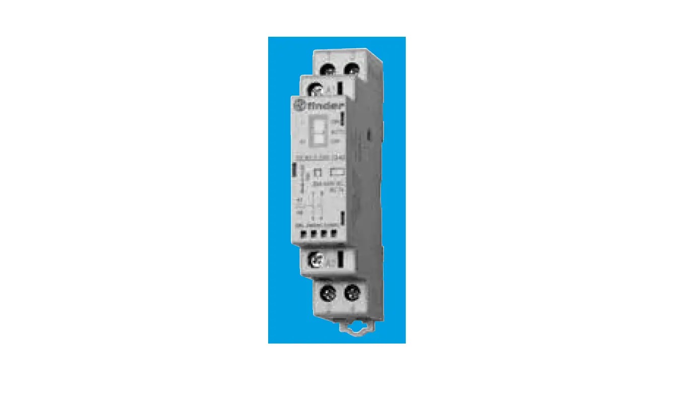
finder 22.32 Modular Contactor 25A
MODULAR CONTACTORS 25 A
Contact gap ≥ 3 mm for NO contacts only; NC contacts ≥ 1.5 mm. Compliant with EN 61095: 2009. AC/DC silent coil (with varistor protection
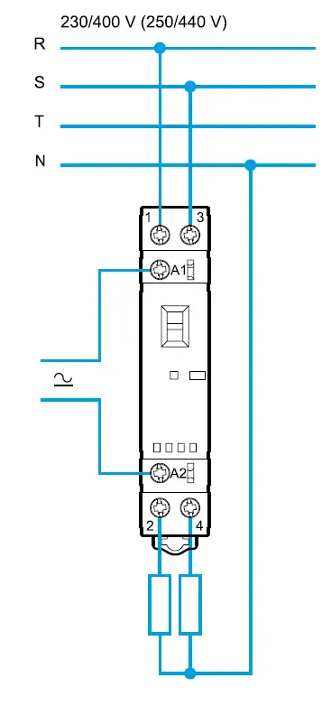
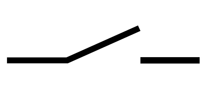
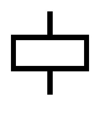
CONNECTION DIAGRAM
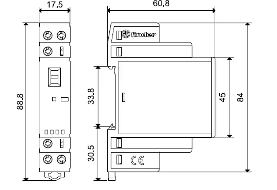
OUTLINE DRAWINGS
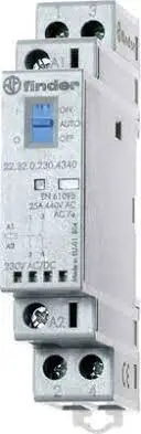
FRONT VIEW
| 022.33 | 2 NO (DPST- NO) |
| 022.35 | 1 NO (SPST- NO) + 1 NC (SPST- NC) |
 | Ith 6 A AC15 700 VA (230 V AC) |
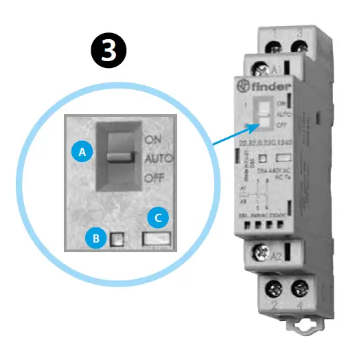
A = Selector (22.32.0.xxx.xx40)
The three-position manual selector has the following functions:
- ON position
The contacts are latched in the operating state (NO contacts -closed and NC contacts – open), the mechanical indicator is visible in its window, the LED is not illuminated. - AUTO position
The state of contacts, mechanical indicator and LED follow the coil supply voltage. - OFF position
Even if terminals A1 – A2 are supplied with rated voltage, the coil is not energized, and so the contacts remain in the non-operated state, the mechanical indicator is not visible and the LED is not illuminated.- B = LED
- C = Mechanical indicator
ACCESSORIES
| 22.32.0.xxx.xxx0 | ||
 | UN (12 – 24 – 48 – 60 – 120 – 230)V AC (50/60 Hz) / DC Umin– Umax (0.8-1.1)UN P 2 VA / 2.2 W | |
|
22.32…x3x0 |
22.32…x5x0 22.32…x4x0 |
| 25 A 440 V AC (EN 61095) | ||
| AC1/ AC-7a (250 V) | 6250 VA | |
| AC3/ AC-7b | 10 A | |
| AC5a (250 V) | 15 A | |
| AC15 (230 V AC) | 1800 VA | |
| M (230 V AC) | 1 kW | |
| DC1 (30 /110/ 220)V | (25/5 /1)A | |
| AC-7c | – (10 A – 22.32…4xx0) | |
| 800 W (2000 W – 22.32…4xx0) | ||
| 300 W (800 W – 22.32…4xx0) | ||
| CFL–LED | 100 W (200 W – 22.32…4xx0) | |
 | (–20…+50)°C | |
| IP20 | ||
- Auxiliary contact module available, “Quick assembly” with the main contactor 022.33/022.35
- It is not possible to assemble the auxiliary module on 22.32.0.xxx.x4x0 (2 NC versions)
OTHER DATA
It is suggested an air gap of 9 mm between adjacent relays for installations and working conditions close to the limit (that is, ambient temperature 40°C, coil operated for a prolonged period of time, all contacts loaded with current > 20 A).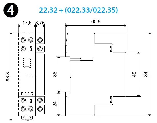
LIST
- Open Type Device – Pollution degree 2 Installation Environment
- Maximum Surrounding Air Temperature 50°C
- The minimum distance among modular contactors 9 mm
- Field Wiring Terminals:
- Use 60/75°C copper conductor only and wire ranges
- No. 10-12-18-24 AWG, Solid only
- Terminal tightening torque 7.0 lb.in. (0.8 Nm)
- Suitable for use on a circuit capable of delivering not more than 5000 ARMS Symmetrical, 240 V ac, when protected by Listed Cartridge Fuses, rated K5 Class (No Current Limiting, Non-Time Delay, max 600 Vac, 30 A, 50 kA A.I.C.) or RK5
- Class (Current Limiting, Time Delay, max 600 Vac, 15 A, 50 kA A.I.C.) or equivalent
- For use in a circuit protected by Type1 or Type2 Surge Protective Devices with “Max Voltage Protection” rating of 3.7 kVpk and
- “Minimum Nominal Discharge Current” of 5 kA (at 6 kV)


