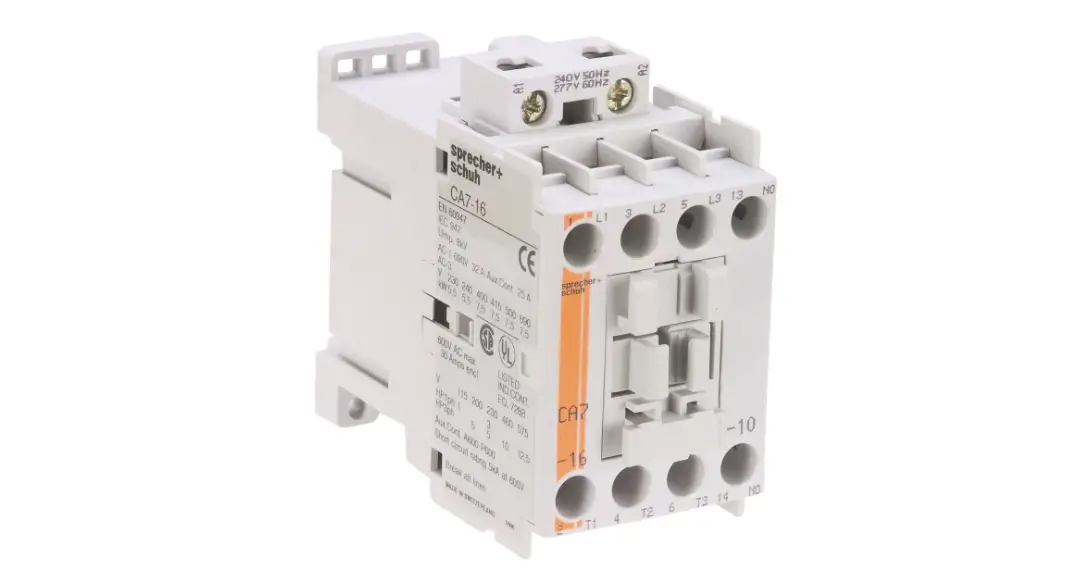
sprecher schuh CA7 Contactors

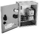
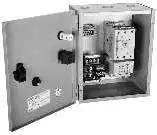
Type 1 General Purpose Enclosures
Enclosure (Box) Kit Includes:
|  |  | ||||||||
| A” Box Kit“ | “B” Box Kit | |||||||||
| Catalog Number | Catalog Number | |||||||||
| M1-1086-A | M1-12106-B | |||||||||
| Optional: 35mm DIN Rail Kit with (2) 10-32 x 1/4” screws ➋ | SF-2 (2 inches long) | SF-3 (3 inches long) | ||||||||
| Dimensions ➏ | 10” x 8” x 6” Type 1 Enclosure | 12” x 10” x 6” Type 1 Enclosure | ||||||||
| For use with Controller | For use with overload | “A” Box Kit accommodates | “B” Box Kit accommodates | |||||||
| CEP7-ED1* | CEP7-EE* | CT7N | Use with No CPT | Use with 50VA CPT ➌ | Space for 2″ DIN Rail ➋ | Use with No CPT | Use with 50VA CPT | Use with 100VA CPT ➌ | Space for 3″ DIN Rail ➋ | |
| Non-reversing Contactors | ||||||||||
| CA7-9…55 | ~ | ~ | ~ | ✔ | ✔ | ✔ | ✔ | ✔ | ✔ | ✔ |
| CA7-60…97 ➐ | ~ | ~ | ~ | No | No | No | ✔ | N/A | ✔ | ✔ |
| Reversing Contactors | ||||||||||
| CAU7-9…37 | ~ | ~ | ~ | ✔ | No | ✔ | ✔ | ✔ | ✔ | ✔ |
| CAU7-43…55 | ~ | ~ | ~ | No | No | No | ✔ | ✔ | ✔ | ✔ |
| CAU7-60…97 ➐ | ~ | ~ | ~ | No | No | No | No | N/A | No | No |
| Non-Reversing Starters | ||||||||||
| CAT7-9…23 | ✔ | ✔ | ➊ | ✔ | ✔ | ✔ | ✔ | ✔ | ✔ | ✔ |
| CAT7-30…55 | ✔ | ✔ | ➊ | ✔ | ✔ | ✔ | ✔ | ✔ | ✔ | ✔ |
| CAT7-60…97 ➐ | N/A | ✔ | ➊ | No | No | No | ✔ | N/A | ✔ | ✔ |
| Reversing Starters | ||||||||||
| CAUT7-9…23 | ✔ | ✔ | ➊ | ✔ | No | ✔ | ✔ | ✔ | ✔ | ✔ |
| CAUT7-30…37 | ✔ | ✔ | ➊ | ✔ | No | ✔ | ✔ | ✔ | ✔ | ✔ |
| CAUT7-43…55 | ✔ | ✔ | ➊ | No | No | No | ✔ | ✔ | ✔ | ✔ |
| CAUT7-60…97 ➐ | N/A | No | No | No | No | No | No | No | No | No |
| NEMA Sized Non-reversing Starters | ||||||||||
| CATN7-12…16 | ✔ | ✔ | ➊ | ✔ | ✔ | ✔ | ✔ | ✔ | ✔ | ✔ |
| CATN7-37 | ✔ | ✔ | ➊ | ✔ | ✔ | ✔ | ✔ | ✔ | ✔ | ✔ |
| CATN7-43 | ✔ | ✔ | ➊ | ✔ | ✔ | ✔ | ✔ | ✔ | ✔ | ✔ |
| CATN7-85 | N/A | ✔ | ➊ | No | No | No | ✔ | N/A | ✔ | ✔ |
- Alternatively CT7N overload relay can be used which will require CT7N-RA3 Reset Adapter. Not included in the kit. Order separately.
- 2” DIN rail can accommodate up to (3) V7-W4 TB’s or equivalent DIN rail mount timers, relays, etc. Order kit SF-2 separately.
3” DIN rail can accommodate up to (6) V7-W4 TB’s or equivalent DIN rail mount timers, relays, etc. Order kit SF-3 separately. - Enclosure designed for use with CPT with top mount secondary fuse, plus back pan mounted Ambus Fuseholder with (2) primary fuses. A CPT and the addition of extra terminal blocks or other control relay using the 2” DIN rail space may require a design change.
- This enclosure is designed for use with a D7 multi-function Start/Stop as standard plus a D7D monolithic pilot light to fit the (2) 22mm knockouts provided. Additional pilot device holes will require field drilling and may interfere with the controller or the addition of a CPT or TB’s.
- (2) 22mm knockout locations are provided for one reset Kit to be located contingent on the type of controller used. See box Instruction sheet for mounting details of controller and reset kit.
- For enclosure dimensions see page C122
- CA7-97 and CAT7-97 will not fit in “B” Box because of wire bending space requirements. See Selection tables for box sizes starting on page C122 for dimensions.
- The CEP7-1ERA reset adapter is a 3rd generation accessory only compatible to 3rd generation CEP7-1 overloads
Pilot Device Kits – All applications (except Kwikstarters and Explosion Proof enclosures)
| Kits | Description | Contact Blocks included | For Use With Enclosure… | Catalog Number | ||
| NO | NC | |||||
 | Multi-Function Pushbutton kit ➋ START-STOP Non-illuminated, Standard for “A” and “B” Box Kits. | 1 | 1 | Type 1, 12, 3R, 4, 4X, 13 | SS6-D7P | |
| Type 1, 12, 3R, 4, 13 | SS6-D7M | |||||
| Multi-Function Pushbutton kit ➋ FORWARD-STOP-REVERSE Non-illuminated, Standard for “A” and “B” Box Kits. | 2 | 3 | Type 1, 12, 3R, 4, 4X, 13 | SS5-D7P | ||
| Type 1, 12, 3R, 4, 13 | SS5-D7M | |||||
 | STOP and START Two button pushbutton kit | 1 | 1 | Type 1, 12, 3R, 4, 4X, 13 | SS1-D7P | |
| Type 1, 12, 3R, 4, 13 | SS1-D7M | |||||
| FORWARD, REVERSE and STOP Three button pushbutton kit | 2 | 3 | Type 1, 12, 3R, 4, 4X, 13 | SS7-D7P | ||
| Type 1, 12, 3R, 4, 13 | SS7-D7M | |||||
 | HAND-OFF-AUTO selector switch kit Name plate included. | 2 | 0 | Type 1, 12, 3R, 4, 4X, 13 | SS2-D7P | |
| Type 1, 12, 3R, 4, 13 | SS2-D7M | |||||
| FWD-OFF-REV selector switch kit Name plate included. | 2 | 0 | Type 1, 12, 3R, 4, 4X, 13 | SS9-D7P | ||
| Type 1, 12, 3R, 4, 13 | SS9-D7M | |||||
| OFF-ON selector switch kit Name plate included. | 1 | 0 | Type 1, 12, 3R, 4, 4X, 13 | SS4-D7P | ||
| Type 1, 12, 3R, 4, 13 | SS4-D7M | |||||

| Monolithic Pilot Light kit LED Lamp and lens cap Does not include nameplate | ~ | Type 1, 12, 3R, 4, 4X, 13 | Green LED 24V AC/DC | D7D-P3N3 | |
| Red LED 24V AC/DC | D7D-P4N3 | |||||
| Green LED 120V AC | D7D-P3N5 | |||||
| Red LED 120V AC | D7D-P4N5 | |||||
| Green LED 240V AC | D7D-P3N7 | |||||
| Red LED 240V AC | D7D-P4N7 | |||||
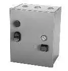 Example of pushbutton kits on an “A” Box
- Pilot Device Kits do not include control wires. See instruction sheet for installation.
- Multi-function START/STOP pushbutton are standard for General Purpose Type 1(M1) dimensions A and B enclosures.
A.C. Coil Codes & Voltage Ranges
All catalog numbers, list prices and enclosure dimensions in the previous section reflect contactors with AC coils. If necessary, add the appropriate price adder to the list price for each coil required as shown in the online catalog. Remember that reversing applications require two coils. Price Adder x 2.
| A.C. Coil Codes (Replace “✱” in cat.# with coil code) | CA7-9 thru CA7-97 CAN7-12…85 | |
| 50 Hz | 60 Hz | |
| 24Z | 24V | 24V |
| 120 | 110V | 120V |
| 220W ➋ | 200-220V | 208-240V |
| 277 | 240V | 277V |
| 415 | 400-415V | ~ |
| 480 | 440V | 480V |
| 600 | 550V | 600V |
All Contactor and Starter Configurations
D.C. Coil Codes & Voltage Ranges ➊➎
For starters with DC coils, select Coil Code from the table below. Remember that reversing applications require two coils (Price Adder x 2). Starter catalog numbers must be modi-fied when using DC coils. For example: For CAT7-9…55 contactors, add an “E” to catalog number for Electronic DC Coils. i.e.: CAT7-9… becomes CAT7-9E… For CAT7-60…97 contactors, add a “D” to catalog number. i.e.: CAT7-60… becomes CAT7-60D…
| D.C. Coil Codes (Replace “✱” in cat.# with coil code) | ➏ CA7-9E..37E CAN7-12E…37E | ➏ CA7-43E …55E CAN7-43E | ➍ CA7-60D…97D CAN7-85D |
| CA7 Code | Voltage | Voltage | Voltage |
| 12E | 12VDCE | 12VDCE | ~ |
| 24E | 24VDCE | 24VDCE | ~ |
| 24DD | ~ | ~ | 24VDC |
| 36E | 36-48VDCE | 36-48VDCE | ~ |
| 48E | 48-72VDCE | 48-72VDCE | ~ |
| 110E | 110VDCE | 110VDCE | ~ |
| 110DD | ~ | ~ | 110VDC |
| ~ | ~ | ~ | ~ |
| 220E | 220VDCE | 220VDCE | ~ |
| 250DD | ~ | ~ | 250VDC |
CAT9 AC/DC Coil Codes and Voltage Ranges ➋➌➎
| Electronic Coils V 24-60V 48-130V 100-250V 250-500V | |||||
| (Replace “✱” in cat.# with coil code) | |||||
| CA9-116…370 | AC/DC | 24W | 48W | 120W | 480W |
| CA9-116-EI…370-EI |
AC/DC with PLC Input | ~ | ~ | 120W | 480W |
| CA9-400-EI…750-EI | 24W ➐ | 48W | 120W | 480W | |
| CA9-860-EI…1060-EI | ~ | ~ | 120W | ~ | |
| CA9-1260-EI | 24W ➐ | 48W | 120W | 480W | |
| CA9-2050-EI…2650-EI | ~ | ~ | 120W | ~ | |
- Only the most common coils are shown here. Other coil voltages may be available. Refer to Contactor Renewal Parts in Section A of this catalog, or contact your nearest Sprecher + Schuh sales office.
- Wide range coil.
- “-EI” designates contactor coil with PLC input. Selections CA9-116…370 with “EI” requires use of control logic on terminals 1, 2, 3. CA9-400 contactors and larger include an integral switch to select use of “EI”.
- “DD” coils are standard for CA7-60D…97D.
- Reversing applications require two coils. Add appropriate price adder(s) to list price of enclosed contactors and starters. Remember to add price for each coil required.
- CA7-9E…55E electronic coils are not interchangeable with non-electronic DC or AC coils.
- This coil range is 24-60V DC only.
CA7 Contactor with CEP7 Overload Relay
| For use with contactor… | Amp Range | Overload Relay Code (◆) | Catalog Number (of Overload Relay) |
| 1-Phase & 3-Phase / Manual reset / Class 10&20 | |||
|
CA7-9…CA7-23 | 0.1…0.5 | 1EAB | CEP7-1EEAB |
| 0.2…1.0 | 1EBB | CEP7-1EEBB | |
| 1.0…5.0 | 1ECB | CEP7-1EECB | |
| 3.2…16 | 1EDB | CEP7-1EEDB | |
| 5.4…27 | 1EEB | CEP7-1EEEB | |
| CA7-30…CA7-55 | 1.0…5.0 | FCP | CEP7-1EFCP ➊ |
| 3.6…16 | FDP | CEP7-1EFDP ➊ | |
| 5.4…27 | 1EED | CEP7-1EEED | |
| 11…55 | 1EFD | CEP7-1EEFD | |
| CA7-60…97 | 20…100 | 1EGE | CEP7-1EEGE |
| 1-Phase & 3-Phase / Auto or Manual / Adj. Trip Class 10…30 | |||
| CA7-9…CA7-23 | 0.1…0.5 | FAB | CEP7-1EFAB |
| 0.2…1.0 | FBB | CEP7-1EFBB | |
| 1.0…5.0 | FCB | CEP7-1EFCB | |
| 3.2…16 | FDB | CEP7-1EFDB | |
| 5.4…27 | FEB | CEP7-1EFEB | |
| CA7-30…CA7-55 | 1.0…5.0 | FCP | CEP7-1EFCP ➊ |
| 3.2…16 | FDP | CEP7-1EFDP ➊ | |
| 5.4…27 | FED | CEP7-1EFED | |
| 11…55 | FFD | CEP7-1EFFD | |
| CA7-55 | 11…55 | FFD | CEP7-1EFFD |
| CA7-60…CA7-97 | 5.4…27 | FEP | CEP7-1EFEP ➊ |
| 11…55 | FFP | CEP7-1EFFP ➊ | |
| 20…100 | FGE | CEP7-1EFGE | |
CA9 Contactor with Overload Relay ➋
| Directly Mounts to Contactor… ➋ | Adj. Range (A) | Overload Relay Code (◆) | CT Ratio | Catalog Number (of Overload Relay) | |
| Automatic or Manual Reset for 3-Phase Applications Adjustable Trip Class 10, 15, 20 & 30 | |||||
|
CA9-116…146 |
30…150 | 9IP ➏ |
~ | CEP9-ESM-I-146-200 CEP9-EIO… CEP9-ECM-PCM | |
| 9IGP ➏ | CEP9-ESM-IG-146-200 CEP9-EIOGP… CEP9-ECM-PCM | ||||
| 9VIGP ➏ | CEP9-ESM-VIG-146-200 CEP9-EIOGP… CEP9-ECM-PCM | ||||
|
CA9-190…205 |
40…200 | 9IP ➏ |
~ | CEP9-ESM-I-205-200 CEP9-EIO… CEP9-ECM-PCM | |
| 9IGP ➏ | CEP9-ESM-IG-205-200 CEP9-EIOGP… CEP9-ECM-PCM | ||||
| 9VIGP ➏ | CEP9-ESM-VIG-205-200 CEP9-EIOGP… CEP9-ECM-PCM | ||||
| CA9-265…305 | CT3 | 300:5 | ➎ | ||
| CA9-370…580 | CT6 | 600:5 | ➎ | ||
| CA9- 750…1060 | ~ | Refer to Factory | |||
Special Notes:
Wye-Delta Starters – First multiply motor full load current by 58%. Then, using this figure, select appropriate Overload Relay Code from tables above.
Part Winding Starters – First multiply motor full load current by 50%. Then, using this figure, select appropriate Overload Relay Code from tables above.
Variable Frequency Drives – CEP7 solid state overload relays cannot be utilized on VFDs or Softstarters with Braking option.
- Engineered solution is a pass-thru model overload. No direct contactor mounting for this selection is available within the CEP7-1EE/1EF series.
- This reference is not intended to be a guide for selecting contactors. Size overload relays using the full load current of the motor.
- The reset time of a CEP7 set in the automatic mode is approximately 180 seconds.
- CEP7 Overload relays do not work with Variable Frequency Drives or any Sprecher + Schuh Softstarter with braking options.
- Utilizes UL approved Current Transformers and a CEP7-1EF_Z overload relay. For CE approved Current Transformers – refer to factory.
- The letter “P” designates the parameter configuration module and can changed to an “E” to represent the use of Ethernet/IP communication module.
CA7 Starters with optional CT7N Bimetallic Overload Relay
| Directly Mounts to Contactor… | Amp Range | Overload Relay Code (◆) | Catalog Number (of Overload Relay used) |
|
CA7-9… CA7-23 Frame “A” | 0.10…0.16 | AA16 | CT7N-23-A16 |
| 0.16…0.25 | AA25 | CT7N-23-A25 | |
| 0.25…0.40 | AA40 | CT7N-23-A40 | |
| 0.35…0.50 | AA50 | CT7N-23-A50 | |
| 0.45…0.63 | AA63 | CT7N-23-A63 | |
| 0.55…0.80 | AA80 | CT7N-23-A80 | |
| 0.75…1.0 | AB10 | CT7N-23-B10 | |
| 0.90…1.3 | AB13 | CT7N-23-B13 | |
| 1.1…1.6 | AB16 | CT7N-23-B16 | |
| 1.4…2.0 | AB20 | CT7N-23-B20 | |
| 1.8…2.5 | AB25 | CT7N-23-B25 | |
| 2.3…3.2 | AB32 | CT7N-23-B32 | |
| 2.9…4.0 | AB40 | CT7N-23-B40 | |
| 3.5…4.8 | AB48 | CT7N-23-B48 | |
| 4.5…6.3 | AB63 | CT7N-23-B63 | |
| 5.5…7.5 | AB75 | CT7N-23-B75 | |
| 7.2…10 | AC10 | CT7N-23-C10 | |
| 9.0…12.5 | AC12 | CT7N-23-C12 | |
| 11.3…16 | AC16 | CT7N-23-C16 | |
| 15…20 | AC20 | CT7N-23-C20 | |
| 17.5…21.5 | AC21 | CT7N-23-C21 | |
| 21…25 | AC25 | CT7N-23-C25 | |
| CA7-30… CA7-37 Frame “B” | 15…20 | BC20 | CT7N-37-C20 |
| 17.5…21.5 | BC21 | CT7N-37-C21 | |
| 21…25 | BC25 | CT7N-37-C25 | |
| 24.5…30 | BC30 | CT7N-37-C30 | |
| 29…36 | BC36 | CT7N-37-C36 | |
| 33…38 | BC38 | CT7N-37-C38 | |
| CA7-43…55 Frame “C” | 17…25 | CC25 | CT7N-43-C25 |
| 24.5…36 | CC36 | CT7N-43-C36 | |
| 35…47 | CC47 | CT7N-43-C47 | |
| 45…60 | CC60 | CT7N-55-C60 | |
| CA7-60… CA7-97 Frame “D” | 35…47 | DC47 | CT7N-85-C47 |
| 45…60 | DC60 | CT7N-85-C60 | |
| 58…75 | DC75 | CT7N-85-C75 | |
| 72…90 | DC90 | CT7N-85-C90 | |
| 85…97 | DC97 | CT7N-97-C97 |
Special Notes:
Wye-Delta Starters – First multiply motor full load current by 58%. Then, using this figure, select appropriate Overload Relay Code from tables above.
Part Winding Starters – First multiply motor full load current by 50%. Then, using this figure, select appropriate Overload Relay Code from tables above.
| Modifications or Special Feature ➋ | Change Last Digit (0) in Catalog Number To: | ||||||||||||||||||||||||||||||||||||||||||||||||||||||||||||||||||||||||||||||||||||||||||||||||
| Pilot Devices In Cover or Flange | |||||||||||||||||||||||||||||||||||||||||||||||||||||||||||||||||||||||||||||||||||||||||||||||||
| “Start-Stop” Pushbutton | 3 | ||||||||||||||||||||||||||||||||||||||||||||||||||||||||||||||||||||||||||||||||||||||||||||||||
| “On-Off” Pushbutton | 4 | ||||||||||||||||||||||||||||||||||||||||||||||||||||||||||||||||||||||||||||||||||||||||||||||||
| “Emergency Stop” Pushbutton – Twist to Release ➌ | 9 | ||||||||||||||||||||||||||||||||||||||||||||||||||||||||||||||||||||||||||||||||||||||||||||||||
| “Hand-Auto” Selector Switch | 5 | ||||||||||||||||||||||||||||||||||||||||||||||||||||||||||||||||||||||||||||||||||||||||||||||||
| “Off-On” Selector Switch | 6 | ||||||||||||||||||||||||||||||||||||||||||||||||||||||||||||||||||||||||||||||||||||||||||||||||
| “Hand-Off-Auto” Selector Switch | 7 | ||||||||||||||||||||||||||||||||||||||||||||||||||||||||||||||||||||||||||||||||||||||||||||||||
| Pilot Light Only ➊ | 1 | ||||||||||||||||||||||||||||||||||||||||||||||||||||||||||||||||||||||||||||||||||||||||||||||||
| Pilot Lights Only (2) ➊ | 2 | ||||||||||||||||||||||||||||||||||||||||||||||||||||||||||||||||||||||||||||||||||||||||||||||||
| Pilot light w/ “Start-Stop” Pushbutton ➊ | 13 | ||||||||||||||||||||||||||||||||||||||||||||||||||||||||||||||||||||||||||||||||||||||||||||||||
| Pilot Light w/ “On-Off” Pushbutton ➊ | 14 | ||||||||||||||||||||||||||||||||||||||||||||||||||||||||||||||||||||||||||||||||||||||||||||||||
| Pilot Light w/ “Hand-Auto” Selector Switch ➊ | 15 | ||||||||||||||||||||||||||||||||||||||||||||||||||||||||||||||||||||||||||||||||||||||||||||||||
| Pilot Light w/ “Off-On” Selector Switch ➊ | 16 | ||||||||||||||||||||||||||||||||||||||||||||||||||||||||||||||||||||||||||||||||||||||||||||||||
| Pilot Light w/ “Hand-Off-Auto” Selector Switch ➊ | 17 | ||||||||||||||||||||||||||||||||||||||||||||||||||||||||||||||||||||||||||||||||||||||||||||||||
| Reversing | “For-Stop-Rev”- Pushbutton | 3 | |||||||||||||||||||||||||||||||||||||||||||||||||||||||||||||||||||||||||||||||||||||||||||||||
| “Up-Stop-Down” Pushbutton | 4 | ||||||||||||||||||||||||||||||||||||||||||||||||||||||||||||||||||||||||||||||||||||||||||||||||
| “Open-Stop-Close” Pushbutton | 5 | ||||||||||||||||||||||||||||||||||||||||||||||||||||||||||||||||||||||||||||||||||||||||||||||||
| Multi- Speed | “High-Stop-Low” Pushbutton | 3 | |||||||||||||||||||||||||||||||||||||||||||||||||||||||||||||||||||||||||||||||||||||||||||||||
| “Fast-Stop-Slow” Pushbutton | 4 | ||||||||||||||||||||||||||||||||||||||||||||||||||||||||||||||||||||||||||||||||||||||||||||||||
| Reversing | “For-Off-Rev” Selector Switch | 6 | |||||||||||||||||||||||||||||||||||||||||||||||||||||||||||||||||||||||||||||||||||||||||||||||
| “Up-Off-Down” Selector Switch | 7 | ||||||||||||||||||||||||||||||||||||||||||||||||||||||||||||||||||||||||||||||||||||||||||||||||
| “Open-Off-Close” Selector Switch | 8 | ||||||||||||||||||||||||||||||||||||||||||||||||||||||||||||||||||||||||||||||||||||||||||||||||
| Multi- Speed | “High-Off-Low” Selector Switch | 5 | |||||||||||||||||||||||||||||||||||||||||||||||||||||||||||||||||||||||||||||||||||||||||||||||
| “Fast-Off-Slow” Selector Switch | 6 | ||||||||||||||||||||||||||||||||||||||||||||||||||||||||||||||||||||||||||||||||||||||||||||||||
| Reversing | Pilot Lights (2) w/ “For-Stop-Rev” Pushbutton ➊ | 23 | |||||||||||||||||||||||||||||||||||||||||||||||||||||||||||||||||||||||||||||||||||||||||||||||
| Pilot Lights (2) w/ “Up-Stop-Down” Pushbutton ➊ | 24 | ||||||||||||||||||||||||||||||||||||||||||||||||||||||||||||||||||||||||||||||||||||||||||||||||
| Pilot Lights (2) w/ “Open-Stop-Close Pushbutton ➊ | 25 | ||||||||||||||||||||||||||||||||||||||||||||||||||||||||||||||||||||||||||||||||||||||||||||||||
| Multi- Speed | Pilot Lights (2) w/ “High-Stop-Low” Pushbutton ➊ | 23 | |||||||||||||||||||||||||||||||||||||||||||||||||||||||||||||||||||||||||||||||||||||||||||||||
| Pilot Lights (2) w/ “Fast-Stop-Slow” Pushbutton ➊ | 24 | ||||||||||||||||||||||||||||||||||||||||||||||||||||||||||||||||||||||||||||||||||||||||||||||||
| Reversing | Pilot Lights (2) w/ “For-Off-Rev” Selector Switch ➊ | 26 | |||||||||||||||||||||||||||||||||||||||||||||||||||||||||||||||||||||||||||||||||||||||||||||||
| Pilot Lights (2) w/ “Up-Off-Down” Selector Switch ➊ | 27 | ||||||||||||||||||||||||||||||||||||||||||||||||||||||||||||||||||||||||||||||||||||||||||||||||
| Pilot Lights (2) w/ “Open-Off-Close Selector Switch ➊ | 28 | ||||||||||||||||||||||||||||||||||||||||||||||||||||||||||||||||||||||||||||||||||||||||||||||||
| Multi- | Pilot Lights (2) w/ “High-Off-Low” Selector Switch ➊ | 25 | |||||||||||||||||||||||||||||||||||||||||||||||||||||||||||||||||||||||||||||||||||||||||||||||
| Pilot Lights (2) w/ “Fast-Off-Slow” Selector Switch ➊ | 26
| ||||||||||||||||||||||||||||||||||||||||||||||||||||||||||||||||||||||||||||||||||||||||||||||||
Ordering Instructions
Change base Catalog Number according to instructions at top of column 2. Example: To Add a “Start-Stop” Pushbutton: change CAT7-30-✱-◆-GO to CAT7-30-✱-◆-G3
- Pilot Lights may be applied with 24VAC/DC, 120VAC or 240VAC control circuit. Pilot Lights with 380 VAC…575VAC require a control circuit transformer.
- Modifications may change dimension of starter enclosure.
- Emergency Stop pushbutton includes inscription ring D7-15YSE112. For other selections from page H68 refer to factory.
| Modifications or Special Feature ➎ | ADD Suffix to Catalog Number | Enclosure Type | ||
| Additional Auxiliary Contacts ➏ | ||||
| 1 N.O. 1 N.C. | L10 L01 | All | ||
| 1 N.O. & 1 N.C. 2 N.O. 2 N.C. | L11 L20 L02 | All | ||
| 1 NO + 2 NC Auxiliary 2 NO + 1 NC Auxiliary 3 NO Auxiliaries 3 NC Auxiliaries | L12 L21 L30 L03 | All | ||
| 2 N.O. & 2 N.C. 1 NO + 3 NC Auxiliary 3 NO + 1 NC Auxiliary 4 NO Auxiliaries 4 NC Auxiliaries | L22 L13 L31 L40 L04 | All | ||
| Alternate Auxiliary Contact Arrangements 1 N.C. in lieu of standard 1 N.O. (on CAT7) 2 N.C. in lieu of standard 2 N.O. (on CAUT7) | LX1 LX2 | All | ||
| Control Circuit Transformer (with fused primary & secondary) | ||||
| Standard Capacity ➌ | Primary Volts 208 240 480 600 380 240 480 600 380 208 120 277 | Secondary Volts 120 120 120 120 110 24 24 24 24 24 24 120 | Replace (✱) in catalog # with following codes ➋➍ XA XB XC XD XG XE XF XJ XK XO XP XY | Type 1, 12, 3R, 4,4X Open |
| Type 7/9 | ||||
|
50 Watt Extra Capacity | 208 240 480 600 240 480 | 120 120 120 120 24 24 | XA05 XB05 XC05 XD05 XE05 XF05 | Type 1, 12, 3R, 4,4X Open |
| Type 7/9 | ||||
| 100 Watt Extra Capacity | 208 240 480 600 240 480 600 | 120 120 120 120 24 24 24 | XA1 XB1 XC1 XD1 XE1 XF1 XJ1 | Type 1, 12, 3R, 4,4X Open |
| Type 7/9 | ||||
| Special Voltage Transformer – Add suffix F/A to end of catalog # ➊ | All, Open | |||
| For applications requiring more than 100 Watt extra capacity | ||||
Ordering Instructions
Change base Catalog Number according to instructions in column 2. Example: To Add a Control Circuit Transformer (480/120) and additional NO/NC auxiliaries: change CAT7-30-✱-◆-GO to CAT7-30-XC-◆-G0-L11.
Note: Separate multiple modification suffixes with a hyphen (-).
- Factory assigned.
- Coil will be factory selected based on transformer secondary.
- See page C112 for detail specifications for Control Circuit Transformer.
- Refer to factory for pricing on larger oversized control circuit transformer selections.
- Modifications may change dimension of starter enclosure.
- Auxiliary addition is per contactor. Quantity is double for reversing applications. Double price adder accordingly.
| Modifications or Special Feature ➋ | Power Supply | Replace (✱) in catalog # with following codes | Enclosure Type | |||||
| Rating (W) | Input V AC | Output V DC | Output Amps | |||||
| @ 40ºC | @ 60ºC | |||||||
| AC to DC Output Power Supplies | ||||||||
| 1-Phase Standard Capacity (CA7-9E…55E) |
Open All | |||||||
| Power Supply (with no CPT) | 72 | 115 | 24 | 2 | 1.5 | PS1P | ||
| Power Supply (with no CPT) | 72 | 230 | 24 | 2 | 1.5 | PS1E | ||
| Power Supply w/CPT @ 208 VAC Primary | 72 | 115 | 24 | 2 | 1.5 | PS1XA | ||
| Power Supply w/CPT @ 230 VAC Primary | PS1XB | |||||||
| Power Supply w/CPT @ 460 VAC Primary | PS1XC | |||||||
| Power Supply w/CPT @ 575 VAC Primary | PS1XD | |||||||
| 1-Phase Standard Capacity (CA7-60D…97D) |
Open All | |||||||
| Power Supply (with no CPT) | 336 | 115 | 24 | 14 | 10 | PS4P | ||
| Power Supply (with no CPT) | 336 | 230 | 24 | 14 | 10 | PS4E | ||
| Power Supply w/CPT @ 208 VAC Primary | 336 | 115 | 24 | 14 | 10 | PS4XA | ||
| Power Supply w/CPT @ 230 VAC Primary | PS4XB | |||||||
| Power Supply w/CPT @ 460 VAC Primary | PS4XC | |||||||
| Power Supply w/CPT @ 575 VAC Primary | PS4XD | |||||||
| 1-Phase 90W Extra Capacity (CA7-9E…55E) |
Open All | |||||||
| Power Supply (with no CPT) | 120 | 115 | 24 | 5 | 4 | PS2P | ||
| Power Supply (with no CPT) | 120 | 230 | 24 | 5 | 4 | PS2E | ||
| Power Supply w/CPT @ 208 VAC Primary | 120 | 115 | 24 | 5 | 4 | PS2XA | ||
| Power Supply w/CPT @ 230 VAC Primary | PS2XB | |||||||
| Power Supply w/CPT @ 460 VAC Primary | PS2XC | |||||||
| Power Supply w/CPT @ 575 VAC Primary | PS2XD | |||||||
| 2-Phase Standard Capacity (CA7-9E…55E) | Open All | |||||||
| Power Supply @ 230 VAC Primary | 120 | 230 | 24 | 5 | 4 | PS6B | ||
| Power Supply @ 460 VAC Primary | 120 | 460 | 24 | 5 | 4 | PS6C | ||
| 2-Phase Standard Capacity (CA7-60D…97D) | Open All | |||||||
| Power Supply @ 230 VAC Primary | 336 | 230 | 24 | 7.5 | 5 | PS7B | ||
| Power Supply @ 460 VAC Primary | 336 | 460 | 24 | 7.5 | 5 | PS7C | ||
| For applications requiring extra capacity on either device, please refer to factory | ||||||||
CRI7E-✱ Electronic Interface Module for use with CA7-9…CA7-97: Interface between the DC control signal from a PLC and the AC operating mechanism of the contactor.
CAT7-30-✱-◆-GO-JE |
add Suffix to end of Catalog Number
-JE |
Open All | ||||||
Ordering Instructions
Replace ✱ in base Catalog Number with Power Supply code. Example: To Add a Standard Capacity Power Supply with Control Circuit Transformer (480/120):
change CAT7-30E-✱-◆-GO to CAT7-30E-PS1XC-◆-G0.
- Not applicable for Series CA9 Starters. CAT9 Starter applications should strongly consider the use of the “EI” functionality included in the CA9-116…1060-EI Contactors. The optional electronic interface selection allows the CA9 contactor to be switched from a PLC or other low-level signal source (15…33V DC) without the need of an interposing relay. The current burden of the interface is 15 mA maximum.
- Modifications may change dimension of starter enclosure.
| Modifications or Special Feature ➌ | ADD Suffix to Catalog Number | Enclosure Type |
| Meters | ||
| Ammeter – Single Phase | AM1 | |
| Ammeter – Three Phase (includes switch) | AM3 | |
| Voltmeter – Single Phase Voltmeter – Three Phase (includes switch) | VM1 VM3 | All, Open |
| Wattmeter | WM | |
| Elapsed Time Meter | ETM | |
| Enclosures | ||
| Space Heater (with N.C. interlock) | HTR | Type 1, 12, 3R, 4, 4X |
| Breather and Drain | BD | Type 7/9 |
| Service Identification Nameplate | F/A ➊ | All |
| Miscellaneous | ||
| Lightning Arrester ➋ | LA | All, Open |
| Surge Capacitor ➋ | SC | |
| Phase Monitor Relay | F/A ➊ | |
| UL508A Panel Label | UL | Type 1, 12, 3R, 4, 4X |
| UL1203 Panel Label (includes 508A) | ULX | Type 7/9 |
Sprecher + Schuh is an ISO9001 company. Our panel shops are UL and ATEX Certified.
Please refer to factory for specifications and label options for the following panel certifications.
UL508A or SUSE label: Most starter assemblies can be supplied with a UL508A ‘Industrial Control Panel’ label. Combination starters can be supplied with Suitable for Service Entrance (SUSE) label. The need for a UL508A or SUSE label must be identified at the time of quotation as well as on the purchase order. The need for a UL508A label may not change the components we would normally use but we must consider all possible requirements at the time we are developing the bill-of-material to be referenced at the time of order entry. Failure to identify the need for a UL508A label or SUSE label at the time of quotation may result in change notice price adders.
ATEX Certification: A requirement for ATEX certification MUST be identified at the time of quotation as well as on the purchase order. ATEX certification of a Type 7/9 explosion proof enclosure definitely requires all conduit and cover openings to be drilled by the enclosure manufacturer. Further, all pilot devices and equipment to be installed must be identified as it controls the heat dissipation which is an ATEX certification requirement. Absolutely no field modification of an ATEX certified starter assembly is allowed. Failure to identify the need for an ATEX certification at the time of quotation and order entry may result in 100% cancelation or re-stocking charge since a new enclosure will be required.
UL1203 Certification: The UL1203 label for explosion proof starters and panels encompasses the UL508A certification. This means all components in a UL1203 labeled panel must first comply with UL508A, and all components in the panel must have a UL label in some form, including the wiring. A special name plate and UL508A label are applied to the panel or starter. A panel is not UL1203 certified unless both label and name plate are present. Contact [email protected] for more information on UL1203 certified panels.
Ordering Instructions
Change base catalog number according to instructions at top of column 2. Example: To add an Elapsed Time Meter and Breather Drain to an explosion-proof starter, change CAT7-30-✱-◆-E0 to CAT7-30-✱-◆-E0-ETM-BD.
Note: Separate multiple modification suffixes with a hyphen (-).
- Factory assigned.
- For Pump Panel controllers.
- Modifications may change dimension of starter enclosure.


