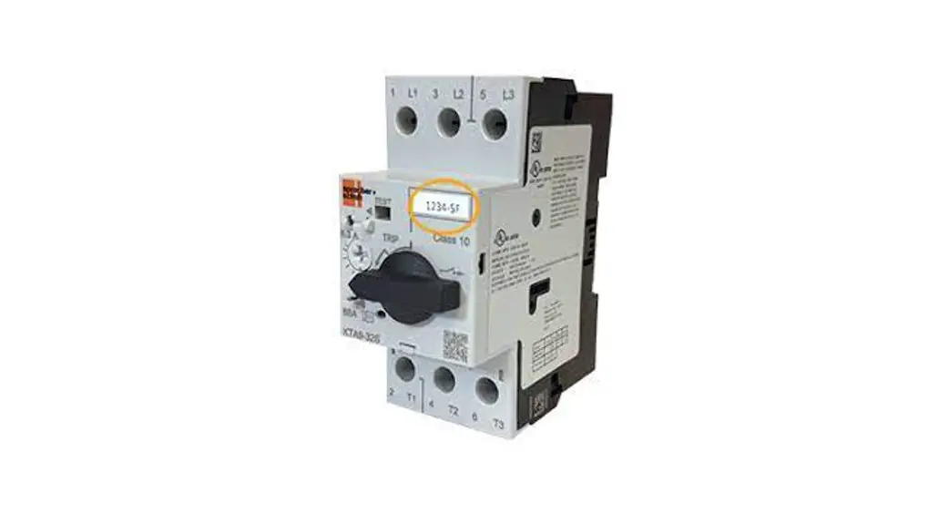
![]() KTA9 Enclosed Motor Controllers
KTA9 Enclosed Motor Controllers
and Molded Case Circuit Breakers
Instruction Manual
 KTA9 Type-E Self-Protected Manual Motor Controllers Page F1.57
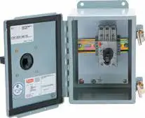 Explosion-Proof Motor Controllers
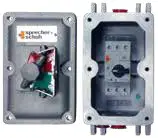 KTA9_EX Page F1.61
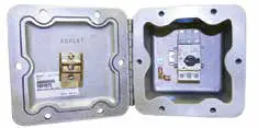 KTA9_EZ Page F1.62
The following pages contain a selection of single enclosed KTA9 & KTC9 motor controllers which can be applied as individual Manual Self-Protected Combination Motor controllers or as individual Manual Motor Starter dependent on the ratings of the individual unit.
- A Self-protected Combination Motor Controller (UL508 Construction Type E) performs all the functions of a Manual Combo starter including a UL-approved means “Disconnect” with a lockable and defeatable handle mechanism, short-circuit protection, and overload protection for motor applications.
- A UL508 Manual Motor Controller is a manual motor starter including a motor disconnect combined with an overload relay.
Both can be combined with auxiliary contacts, shunt-trip, or under-voltage trip units to meet your application requirements. The section that follows includes non-metallic enclosures, metallic enclosures, and explosion-proof enclosures.
Enclosed Molded Case Circuit Breakers
The following pages contain a selection of individual enclosed KTU9 molded case circuit breakers for the protection of non-motor loads. KTU9 is a 480Y/277Volt or 600Y/347 volt UL489 approved circuit breaker and the selection of enclosures or combined with a matching environmentally approved thru-the-door handle disconnect mechanism which also complies with UL489 standards. KTU9 offers at least 65 KAIC withstand ratings which exceed those offered by many 600 Volt Class Molded Case Circuit Breakers which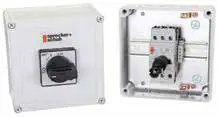 KTU9 Molded Case Circuit Breakers Page F1.63are larger and more expensive. Enclosed KTU9 can be combined with auxiliary contacts, shunt-trip, or under-voltage trip units to meet your application requirements.
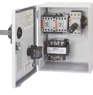
Enclosed Type E/F Combination Starters
KTA9 or KTC9 can be applied in combination with a CA7 contactor for remote control and an enclosure with a matching environmentally approved thru-the-door handle disconnect mechanism to meet all requirements for a Construction Type E or F Combination Starter. The following pages contain a selection of individual Combo starters which are smaller and less expensive than Classic Construction Type A (Fusible), or Type C (Thermal-magnetic Molded Case Circuit Breaker) as offered in Section C of this catalog. The following types are offered:
- Non-metallic enclosed Combo KwikStarter CX7 and CXU7 with AC or DC coils available as factory assembled or in kit form for field assembly
- Metallic enclosed Combo CX7 and CXU7with AC or DC coils
- Explosion-proof enclosed CX7 and CX7 Ecombo KWIKStarters Page F1.66 CXU7with AC or DC coils A variety of modifications are available.
Enclosed KTA9 – IP65
Amp / Horsepower Rating | Non-metallic (IP65) Enclosure | ||||||
| Max. Horsepower ➊➋➌ | O/L Relay Ampere Range | Magnetic Res. Current | Catalog Number ➍ | Dimension Code | |||
| Three Phase | |||||||
| 200V | 230V | 460V | 575V | ||||
| ~ | ~ | ~ | ~ | 0.10…0.16 | 2.2 | KTA9-32S-0.16A-CG | AY |
| ~ | ~ | ~ | ~ | 0.16…0.25 | 3.5 | KTA9-32S-0.25A-CG | AY |
| ~ | ~ | ~ | ~ | 0.25…0.40 | 5.6 | KTA9-32S-0.4A-CG | AY |
| ~ | ~ | ~ | ~ | 0.40…0.63 | 8.8 | KTA9-32S-0.63A-CG | AY |
| ~ | ~ | 1/2 | 1/2 | 0.63…1.0 | 14 | KTA9-32S-1.0A-CG | AY |
| ~ | ~ | 3/4 | ~ | 1.0…1.6 | 22 | KTA9-32S-1.6A-CG | AY |
| 1/2 | 1/2 | 1 | 1-1/2 | 1.6…2.5 | 35 | KTA9-32S-2.5A-CG | AY |
| 3/4 | 3/4 | 2 | 3 | 2.5…4.0 | 52 | KTA9-32S-4.0A-CG | AY |
| 1 | 1-1/2 | 3 | 5 ➍ | 4.0…6.3 | 88 | KTA9-32S-6.3A-CG | AY |
| 2 | 2 | 5 | 7-1/2 ➍ | 6.3…10 | 140 | KTA9-32S-10A-CG | AY |
| 3 | 5 | 10 | 10 ➍ | 10…16 | 224 | KTA9-32S-16A-CG | AY |
| 5 ➍ | 5 ➍ | 10 ➍ | 15 ➍ | 14.5…20 | 280 | KTA9-32S-20A-CG | AY |
| 5 ➍ | 7-1/2 ➍ | 15 ➍ | 20 ➍ | 18…25 | 330 | KTA9-32S-25A-CG | AY |
| 7-1/2 ➍ | 10 ➍ | 20 ➍ | 25 ➍ | 24…29 | 406 | KTA9-32S-29A-CG | AY |
| 7-1/2 ➍ | 10 ➍ | 20 ➍ | 30 ➍ | 27…32 | 448 | KTA9-32S-32A-CG | AY |
➊ Horsepower ratings shown in the table above are for reference. The final selection of the controller depends on the actual motor full load current and service factor.
• For motor with service factor less than 1.15. Use motor nameplate full load current times 0.9 and choose the motor starter with the appropriate current range. Example: Motor FLC = 4.2A; S.F. = 1.0. 4.2A x 0.9 = 3.78A. Select catalog number KTA9-32S-4.0A.
➋ Magnetic trip is fixed at 14x the maximum value of the current adjustment range. Refer to page F5 for applied KAIC ratings.
➌ KTA9 may be applied to single-phase loads if 3 poles of the device are wired in series. See footnote 1 for device selection criteria.
➍ A red and yellow handle may be selected instead of the standard gray and black handle. Change the “CG” suffix to “CJ”. Ex: Change KTA9-32S-0.16A-CG to KTA9-32S-0.16A-CJ.
➎ Handles are built-in to the enclosure and are not available as components.
➏ Catalog numbers with specific voltages (i.e. @ 575V) shaded in gray are suitable for use as a manual motor starter only because they are not Type E rated. See page F5 for ratings.
Includes:
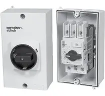
- Non-metallic (IP65) enclosure with integrated IP65 operator – watertight, dust-tight
- KTA9-32S (Standard Interrupting Capacity) “Type E” Self-protected Combination Manual Controller ➎
- Terminal Adaptor for Type E Applications (Cat.# KT9-40-TE)
- Gray and black IP65 handle ➍➎
- Non-metallic (IP65) enclosure with integrated IP65 operator – watertight, dust-tight
- KTA9-32S (Standard Interrupting Capacity) “Type E” Self-protected Combination Manual Controller ➎
- Terminal Adaptor for Type E Applications (Cat.# KT9-40-TE)
- Gray and black IP65 handle ➍➎
Enclosure Only
Description | Catalog Number |
| Gray/Black handle | KT9-ENN |
| Red/Yellow handle | KT9-ENTRY |
Modifications (Factory Assembled)
| Description | Add Suffix to Cat. Number |
| KT9 Auxiliaries & Trip Contacts, Front Mount 250V max. 1 NO Auxiliary 1 NC Auxiliary 1 NO + 1 NC Auxiliary 2 NO Auxiliaries 1 NO SC+OL + 1 NC Auxiliary 1 NO SC+OL + 1 NO Auxiliary Side Mount 600V max. 2 NC Auxiliaries 2 NO Auxiliaries 1 NO + 1 NC Auxiliary | -B -A -C -D -R -S -AS02 -AS20 -AS11 |
| Additional KT9 Trip Contacts, Side Mount 600V max. 1 NO SC+OL+1 NO SC 1 NO SC+OL+1 NC SC 1 NC SC+OL+1 NO SC | -R00 -R01 -R10 |
| Accessories Undervoltage Release Module Shunt Release Module | -UA-✱ -AA-✱ |
-UA..-AA Coil Codes (✱)
| AC Coil Code | Voltage Range | |
| 50 Hz | 60 Hz | |
| 24V | 21V | 24V |
| 28V | 24V | 28V |
| 120V | 105V | 120V |
| 127V | 110V | 127V |
| 230V | 220…230V | ~ |
| 240V | ~ | 240…260V |
| 277V | 240V | 277V |
| 460V | 380…400V | 400…460V |
| 480V | 415V | 480V |
| 600V | 550V | 600V |
Enclosed KTA9 – Type 4 / 4X / 12
| Amp / Horsepower Rating | Non-metallic, Type 4 / 4X / 12 Enclosure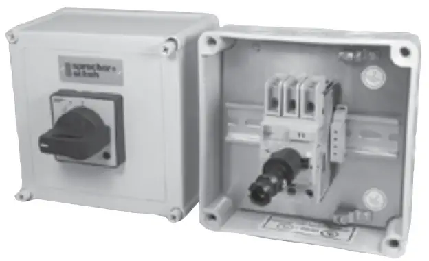 | ||||||
| Max. Horsepower ➊➋ | O/L Relay Ampere Range | Magnetic Res. Current | Catalog Number ➌ | Dim Code | |||
| Three Phase | |||||||
| 200V | 230V | 460V | 575V | ||||
KTA9-32S Standard Interrupting Capacity | |||||||
| ~ | ~ | ~ | ~ | 0.10…0.16 | 2.2 | KTA9-32S-0.16A-VG | Q5 |
| ~ | ~ | ~ | ~ | 0.16…0.25 | 3.5 | KTA9-32S-0.25A-VG | Q5 |
| ~ | ~ | ~ | ~ | 0.25…0.40 | 5.6 | KTA9-32S-0.40A-VG | Q5 |
| ~ | ~ | ~ | ~ | 0.40…0.63 | 8.8 | KTA9-32S-0.63A-VG | Q5 |
| ~ | ~ | 1/2 | 1/2 | 0.63…1.0 | 14 | KTA9-32S-1.0A-VG | Q5 |
| ~ | ~ | 3/4 | ~ | 1.0…1.6 | 22 | KTA9-32S-1.6A-VG | Q5 |
| 1/2 | 1/2 | 1 | 1-1/2 | 1.6…2.5 | 35 | KTA9-32S-2.5A-VG | Q5 |
| 3/4 | 3/4 | 2 | 3 | 2.5…4.0 | 52 | KTA9-32S-4.0A-VG | Q5 |
| 1 | 1-1/2 | 3 | 5 ➍ | 4.0…6.3 | 88 | KTA9-32S-6.3A-VG ➍ | Q5 |
| 2 | 2 | 5 | 7-1/2 ➍ | 6.3…10 | 140 | KTA9-32S-10A-VG ➍ | Q5 |
| 3 | 5 | 10 | 10 ➍ | 10…16 | 224 | KTA9-32S-16A-VG ➍ | Q5 |
| 5 ➍ | 5 ➍ | 10 ➍ | 15 ➍ | 14.5…20 | 280 | KTA9-32S-20A-VG ➍ | Q5 |
| 5 ➍ | 7-1/2 ➍ | 15 ➍ | 20 ➍ | 18…25 | 330 | KTA9-32S-25A-VG ➍ | Q5 |
| 7-1/2 ➍ | 10 ➍ | 20 ➍ | 25 ➍ | 24…29 | 406 | KTA9-32S-29A-VG ➍ | Q5 |
| 7-1/2 ➍ | 10 ➍ | 20 ➍ | 30 ➍ | 27…32 | 448 | KTA9-32S-32A-VG ➍ | Q5 |
KTA9-40H High Interrupting Capacity | |||||||
| ~ | ~ | ~ | ~ | 0.40…0.63 | 8.8 | KTA9-40H-0.63A-VG | Q6 |
| ~ | ~ | 1/2 | 1/2 | 0.63…1.0 | 14 | KTA9-40H-1.0A-VG | Q6 |
| ~ | ~ | 3/4 | ~ | 1.0…1.6 | 22 | KTA9-40H-1.6A-VG | Q6 |
| 1/2 | 1/2 | 1 | 1-1/2 | 1.6…2.5 | 33 | KTA9-40H-2.5A-VG | Q6 |
| 3/4 | 3/4 | 2 | 3 | 2.5…4.0 | 52 | KTA9-40H-4.0A-VG | Q6 |
| 1 | 1-1/2 | 3 | 5 | 4.0…6.3 | 82 | KTA9-40H-6.3A-VG | Q6 |
| 2 | 2 | 5 | 7-1/2 | 6.3…10 | 130 | KTA9-40H-10A-VG | Q6 |
| 3 | 5 | 10 | 10 | 10…16 | 208 | KTA9-40H-16A-VG | Q6 |
| 5 | 5 | 10 | 15 ➍ | 14.5…20 | 260 | KTA9-40H-20A-VG ➍ | Q6 |
| 5 | 7-1/2 | 15 | 20 ➍ | 18…25 | 325 | KTA9-40H-25A-VG ➍ | Q6 |
| 7-1/2 | 10 | 20 | 25 ➍ | 24…29 | 406 | KTA9-40H-29A-VG ➍ | Q6 |
| 7-1/2 | 10 | 20 | 30 ➍ | 27…32 | 448 | KTA9-40H-32A-VG ➍ | Q6 |
| 10 | 10 | 25 | 30 ➍ | 30…36 | 432 | KTA9-40H-36A-VG ➍ | Q6 |
| 10 | 10 | 30 | 30 ➍ | 34…40 | 480 | KTA9-40H-40A-VG ➍ | Q6 |
KTA7-45H High Interrupting Capacity | |||||||
| 2 | 3 | 5 | 7-1/2 | 6.3…10 | 130 | KTA7-45H-10A-VG | Q7 |
| 3 | 5 | 10 | 10 | 10…16 | 208 | KTA7-45H-16A-VG | Q7 |
| 5 | 5 | 10 | 15 | 14.5…20 | 260 | KTA7-45H-20A-VG | Q7 |
| 7-1/2 | 7-1/2 | 15 | 20 | 18…25 | 325 | KTA7-45H-25A-VG | Q7 |
| 7-1/2 | 10 | 20 | 30 | 23…32 | 416 | KTA7-45H-32A-VG | Q7 |
| 10 | 15 | 30 | 40 ➍ | 32…45 | 585 | KTA7-45H-45A-VG | Q7 |
Enclosed KTA9 – Type 12
| Amp / Horsepower Rating | Painted Steel, Type 12 Enclosure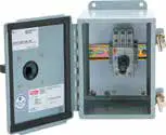 | ||||||
| Max. Horsepower ➊➋➌ | O/L Relay Ampere Range | Magnetic Res. Current | Catalog Number ➍ | Dim Code | |||
| Three Phase | |||||||
| 200V | 230V | 460V | 575V | ||||
KTA9-32S Standard Interrupting Capacity | |||||||
| ~ | ~ | ~ | ~ | 0.10…0.16 | 2.2 | KTA9-32S-0.16A-DG | L |
| ~ | ~ | ~ | ~ | 0.16…0.25 | 3.5 | KTA9-32S-0.25A-DG | L |
| ~ | ~ | ~ | ~ | 0.25…0.40 | 5.6 | KTA9-32S-0.40A-DG | L |
| ~ | ~ | ~ | ~ | 0.40…0.63 | 8.8 | KTA9-32S-0.63A-DG | L |
| ~ | ~ | 1/2 | 1/2 | 0.63…1.0 | 14 | KTA9-32S-1.0A-DG | L |
| ~ | ~ | 3/4 | ~ | 1.0…1.6 | 22 | KTA9-32S-1.6A-DG | L |
| 1/2 | 1/2 | 1 | 1-1/2 | 1.6…2.5 | 35 | KTA9-32S-2.5A-DG | L |
| 3/4 | 3/4 | 2 | 3 | 2.5…4.0 | 52 | KTA9-32S-4.0A-DG | L |
| 1 | 1-1/2 | 3 | 5 ➍ | 4.0…6.3 | 88 | KTA9-32S-6.3A-DG ➍ | L |
| 2 | 2 | 5 | 7-1/2 ➍ | 6.3…10 | 140 | KTA9-32S-10A-DG ➍ | L |
| 3 | 5 | 10 | 10 ➍ | 10…16 | 224 | KTA9-32S-16A-DG ➍ | L |
| 5 ➍ | 5 ➍ | 10 ➍ | 15 ➍ | 14.5…20 | 280 | KTA9-32S-20A-DG ➍ | L |
| 5 ➍ | 7-1/2 ➍ | 15 ➍ | 20 ➍ | 18…25 | 330 | KTA9-32S-25A-DG ➍ | L |
| 7-1/2 ➍ | 10 ➍ | 20 ➍ | 25 ➍ | 24…29 | 406 | KTA9-32S-29A-DG ➍ | L |
| 7-1/2 ➍ | 10 ➍ | 20 ➍ | 30 ➍ | 27…32 | 448 | KTA9-32S-32A-DG ➍ | L |
KTA9-40H High Interrupting Capacity | |||||||
| ~ | ~ | ~ | ~ | 0.40…0.63 | 8.8 | KTA9-40H-0.63A-DG | L |
| ~ | ~ | 1/2 | 1/2 | 0.63…1.0 | 14 | KTA9-40H-1.0A-DG | L |
| ~ | ~ | 3/4 | ~ | 1.0…1.6 | 22 | KTA9-40H-1.6A-DG | L |
| 1/2 | 1/2 | 1 | 1-1/2 | 1.6…2.5 | 33 | KTA9-40H-2.5A-DG | L |
| 3/4 | 3/4 | 2 | 3 | 2.5…4.0 | 52 | KTA9-40H-4.0A-DG | L |
| 1 | 1-1/2 | 3 | 5 | 4.0…6.3 | 82 | KTA9-40H-6.3A-DG | L |
| 2 | 2 | 5 | 7-1/2 | 6.3…10 | 130 | KTA9-40H-10A-DG | L |
| 3 | 5 | 10 | 10 | 10…16 | 208 | KTA9-40H-16A-DG | L |
| 5 | 5 | 10 | 15 ➍ | 14.5…20 | 260 | KTA9-40H-20A-DG ➍ | L |
| 5 | 7-1/2 | 15 | 20 ➍ | 18…25 | 325 | KTA9-40H-25A-DG ➍ | L |
| 7-1/2 | 10 | 20 | 25 ➍ | 24…29 | 406 | KTA9-40H-29A-DG ➍ | L |
| 7-1/2 | 10 | 20 | 30 ➍ | 27…32 | 448 | KTA9-40H-32A-DG ➍ | L |
| 10 | 10 | 25 | 30 ➍ | 30…36 | 432 | KTA9-40H-36A-DG ➍ | L |
| 10 | 10 | 30 | 30 ➍ | 34…40 | 480 | KTA9-40H-40A-DG ➍ | L |
Enclosed KTA9 – Type 4 / 12
| Amp / Horsepower Rating | Painted Steel, Type 4 / 12 Enclosure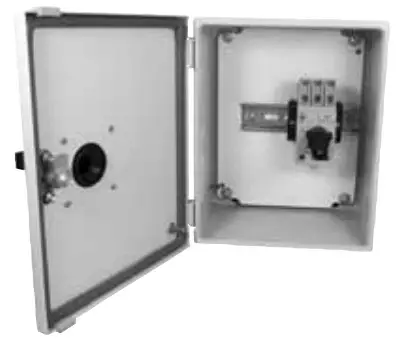 | ||||||
| Max. Horsepower ➊➋ | O/L Relay Ampere Range | Magnetic Res. Current | Catalog Number ➌ | Dim Code | |||
| Three Phase | |||||||
| 200V | 230V | 460V | 575V | ||||
KTA9-32S Standard Interrupting Capacity | |||||||
| ~ | ~ | ~ | ~ | 0.10…0.16 | 2.2 | KTA9-32S-0.16A-WG | W6 |
| ~ | ~ | ~ | ~ | 0.16…0.25 | 3.5 | KTA9-32S-0.25A-WG | W6 |
| ~ | ~ | ~ | ~ | 0.25…0.40 | 5.6 | KTA9-32S-0.40A-WG | W6 |
| ~ | ~ | ~ | ~ | 0.40…0.63 | 8.8 | KTA9-32S-0.63A-WG | W6 |
| ~ | ~ | 1/2 | 1/2 | 0.63…1.0 | 14 | KTA9-32S-1.0A-WG | W6 |
| ~ | ~ | 3/4 | ~ | 1.0…1.6 | 22 | KTA9-32S-1.6A-WG | W6 |
| 1/2 | 1/2 | 1 | 1-1/2 | 1.6…2.5 | 35 | KTA9-32S-2.5A-WG | W6 |
| 3/4 | 3/4 | 2 | 3 | 2.5…4.0 | 52 | KTA9-32S-4.0A-WG | W6 |
| 1 | 1-1/2 | 3 | 5 ➍ | 4.0…6.3 | 88 | KTA9-32S-6.3A-WG ➍ | W6 |
| 2 | 2 | 5 | 7-1/2 ➍ | 6.3…10 | 140 | KTA9-32S-10A-WG ➍ | W6 |
| 3 | 5 | 10 | 10 ➍ | 10…16 | 224 | KTA9-32S-16A-WG ➍ | W6 |
| 5 ➍ | 5 ➍ | 10 ➍ | 15 ➍ | 14.5…20 | 280 | KTA9-32S-20A-WG ➍ | W6 |
| 5 ➍ | 7-1/2 ➍ | 15 ➍ | 20 ➍ | 18…25 | 330 | KTA9-32S-25A-WG ➍ | W6 |
| 7-1/2 ➍ | 10 ➍ | 20 ➍ | 25 ➍ | 24…29 | 406 | KTA9-32S-29A-WG ➍ | W6 |
| 7-1/2 ➍ | 10 ➍ | 20 ➍ | 30 ➍ | 27…32 | 448 | KTA9-32S-32A-WG ➍ | W6 |
KTA9-40H High Interrupting Capacity | |||||||
| ~ | ~ | ~ | ~ | 0.40…0.63 | 8.8 | KTA9-40H-0.63A-VG | W6 |
| ~ | ~ | 1/2 | 1/2 | 0.63…1.0 | 14 | KTA9-40H-1.0A-VG | W6 |
| ~ | ~ | 3/4 | ~ | 1.0…1.6 | 22 | KTA9-40H-1.6A-VG | W6 |
| 1/2 | 1/2 | 1 | 1-1/2 | 1.6…2.5 | 33 | KTA9-40H-2.5A-WG | W6 |
| 3/4 | 3/4 | 2 | 3 | 2.5…4.0 | 52 | KTA9-40H-4.0A-WG | W6 |
| 1 | 1-1/2 | 3 | 5 | 4.0…6.3 | 82 | KTA9-40H-6.3A-WG | W6 |
| 2 | 2 | 5 | 7-1/2 | 6.3…10 | 130 | KTA9-40H-10A-WG | W6 |
| 3 | 5 | 10 | 10 | 10…16 | 208 | KTA9-40H-16A-WG | W6 |
| 5 | 5 | 10 | 15 ➍ | 14.5…20 | 260 | KTA9-40H-20A-WG ➍ | W6 |
| 5 | 7-1/2 | 15 | 20 ➍ | 18…25 | 325 | KTA9-40H-25A-WG ➍ | W6 |
| 7-1/2 | 10 | 20 | 25 ➍ | 24…29 | 406 | KTA9-40H-29A-WG➍ | W6 |
| 7-1/2 | 10 | 20 | 30 ➍ | 27…32 | 448 | KTA9-40H-32A-WG➍ | W6 |
| 10 | 10 | 25 | 30 ➍ | 30…36 | 432 | KTA9-40H-36A-WG ➍ | W6 |
| 10 | 10 | 30 | 30 ➍ | 34…40 | 480 | KTA9-40H-40A-WG ➍ | W6 |
KTA7-45H High Interrupting Capacity | |||||||
| 2 | 3 | 5 | 7-1/2 | 6.3…10 | 130 | KTA7-45H-10A-WG | R/F |
| 3 | 5 | 10 | 10 | 10…16 | 208 | KTA7-45H-16A-WG | R/F |
| 5 | 5 | 10 | 15 | 14.5…20 | 260 | KTA7-45H-20A-WG | R/F |
| 7-1/2 | 7-1/2 | 15 | 20 | 18…25 | 325 | KTA7-45H-25A-WG | R/F |
| 7-1/2 | 10 | 20 | 30 | 23…32 | 416 | KTA7-45H-32A-WG | R/F |
| 10 | 15 | 30 | 40 ➍ | 32…45 | 585 | KTA7-45H-45A-WG ➍ | R/F |
KTA9 Explosion Proof Motor Controllers – NEMA Type 7/9
Manual Motor Controller
Explosion-Proof Series KTA9
| Amp / Horsepower Rating | | ||||||
| Max. Horsepower ➊➋ | O/L Relay Ampere Range | Magnetic Res. Current | Catalog Number | Dim Code | |||
| Three Phase | |||||||
| 200V | 230V | 460V | 575V | ||||
KTA9-32S Standard Interrupting Capacity | |||||||
| ~ | ~ | ~ | ~ | 0.10…0.16 | 2.2 | KTA9-32S-0.16A-EX | EX |
| ~ | ~ | ~ | ~ | 0.16…0.25 | 3.5 | KTA9-32S-0.25A-EX | EX |
| ~ | ~ | ~ | ~ | 0.25…0.40 | 5.6 | KTA9-32S-0.4A-EX | EX |
| ~ | ~ | ~ | ~ | 0.40…0.63 | 8.8 | KTA9-32S-0.63A-EX | EX |
| ~ | ~ | 1/2 | 1/2 | 0.63…1.0 | 14 | KTA9-32S-1.0A-EX | EX |
| ~ | ~ | 3/4 | ~ | 1.0…1.6 | 22 | KTA9-32S-1.6A-EX | EX |
| 1/2 | 1/2 | 1 | 1-1/2 | 1.6…2.5 | 35 | KTA9-32S-2.5A-EX | EX |
| 3/4 | 3/4 | 2 | 3 | 2.5…4.0 | 52 | KTA9-32S-4.0A-EX | EX |
| 1 | 1-1/2 | 3 | 5 ➌ | 4.0…6.3 | 88 | KTA9-32S-6.3A-EX ➌ | EX |
| 2 | 2 | 5 | 7-1/2 ➌ | 6.3…10 | 140 | KTA9-32S-10A-EX ➌ | EX |
| 3 | 5 | 10 | 10 ➌ | 10…16 | 224 | KTA9-32S-16A-EX ➌ | EX |
| 5 ➌ | 5 ➌ | 10 ➌ | 15 ➌ | 14.5…20 | 280 | KTA9-32S-20A-EX ➌ | EX |
| 5 ➌ | 7-1/2 ➌ | 15 ➌ | 20 ➌ | 18…25 | 330 | KTA9-32S-25A-EX ➌ | EX |
| 7-1/2 ➌ | 10 ➌ | 20 ➌ | 25 ➌ | 24…29 | 406 | KTA9-32S-29A-EX ➌ | EX |
| 7-1/2 ➌ | 10 ➌ | 20 ➌ | 30 ➌ | 27…32 | 448 | KTA9-32S-32A-EX ➌ | EX |
Includes:
- Class I, Div 1, 2, Group C, D
Class II, Div 1, 2, Group E, F & G enclosure
Class III
NEMA Type 7/9 - KTA9 “Type E” Self-protected Combination
Manual Motor Controller ➌ - Terminal Adaptor for Type E Applications (Cat.# KT9-40-TE)
Modifications (Factory Assembled)
| Description | Add Suffix to Cat. Number |
| KT9 Auxiliaries & Trip Contacts, | |
| Front Mount 250V max. | |
| 1 NO Auxiliary | -B |
| 1 NC Auxiliary | -A |
| 1 NO + 1 NC Auxiliary | -C |
| 2 NO Auxiliaries | -D |
| 1 NO SC+OL + 1 NC | -R |
| 1 NO SC+OL + 1 NO | -S |
| Side Mount 600V max. | |
| 2 NC Auxiliaries | -AS02 |
| 2 NO Auxiliaries | -AS20 |
| 1 NO + 1 NC Auxiliary | -AS11 |
| Additional KT9 Trip Contacts, | |
| Side Mount 600V max. | |
| 1 NO SC+OL+1 NO SC | -R00 |
| 1 NO SC+OL+1 NC SC | -R01 |
| 1 NC SC+OL+1 NO SC | -R10 |
| Accessories Undervoltage Release Module Shunt Release Module | -UA-✱ -AA-✱ |
| Enclosure Modifications Breather/Drain | -BD |
➊ Horsepower ratings shown in the table above are for reference. The final selection of the controller depends on the actual motor full load current and service factor.
- For motors with a service factor less than 1.15. Use motor nameplate full load current times 0.9 and choose the motor starter with the appropriate current
➋ KTA9 may be applied to single-phase loads if 3 poles of the device are wired in series. See footnote 1 for device selection criteria.
➌ Catalog numbers with specific voltages (i.e. @ 575V) shaded in gray are suitable for use as a manual motor starter only because they are not Type E range. Example: Motor FLC = 4.2A; S.F. = 1.0. 4.2A x 0.9 = 3.78A. Select rated. See page F5 for ratings. catalog number KTA9-32S-0.40A.
➍ -UA✱ and -AA✱ options not possible in the -EX Enclosure.
KTA9 Explosion Proof Motor Controllers – NEMA Type 4/7/9 with Gasket
Self-protected Manual Motor Controller Explosion-Proof Series KTA9
| Amp / Horsepower Rating | EY Enclosure shown | ||||||
| Max. Horsepower ➊➋ | O/L Relay Ampere Range | Magnetic Res. Current | Catalog Number ➌ | Dim Code | |||
| Three Phase | |||||||
| 200V | 230V | 460V | 575V | ||||
KTA9-32S Standard Interrupting Capacity | |||||||
| ~ | ~ | ~ | ~ | 0.10…0.16 | 2.2 | KTA9-32S-0.16A-EY | EY |
| ~ | ~ | ~ | ~ | 0.16…0.25 | 3.5 | KTA9-32S-0.25A-EY | EY |
| ~ | ~ | ~ | ~ | 0.25…0.40 | 5.6 | KTA9-32S-0.40A-EY | EY |
| ~ | ~ | ~ | ~ | 0.40…0.63 | 8.8 | KTA9-32S-0.63A-EY | EY |
| ~ | ~ | 1/2 | 1/2 | 0.63…1.0 | 14 | KTA9-32S-1.0A-EY | EY |
| ~ | ~ | 3/4 | ~ | 1.0…1.6 | 22 | KTA9-32S-1.6A-EY | EY |
| 1/2 | 1/2 | 1 | 1-1/2 | 1.6…2.5 | 35 | KTA9-32S-2.5A-EY | EY |
| 3/4 | 3/4 | 2 | 3 | 2.5…4.0 | 52 | KTA9-32S-4.0A-EY | EY |
| 1 | 1-1/2 | 3 | 5 ➌ | 4.0…6.3 | 88 | KTA9-32S-6.3A-EY | EY |
| 2 | 2 | 5 | 7-1/2 ➌ | 6.3…10 | 140 | KTA9-32S-10A-EY | EY |
| 3 | 5 | 10 | 10 ➌ | 10…16 | 224 | KTA9-32S-16A-EY | EY |
| 5 ➌ | 5 ➌ | 10 ➌ | 15 ➌ | 14.5…20 | 280 | KTA9-32S-20A-EY | EY |
| 5 ➌ | 7-1/2 ➌ | 15 ➌ | 20 ➌ | 18…25 | 330 | KTA9-32S-25A-EY | EY |
| 7-1/2 ➌ | 10 ➌ | 20 ➌ | 25 ➌ | 24…29 | 406 | KTA9-32S-29A-EY | EY |
| 7-1/2 ➌ | 10 ➌ | 20 ➌ | 30 ➌ | 27…32 | 448 | KTA9-32S-32A-EY | EY |
KTA9-40H High Interrupting Capacity | |||||||
| ~ | ~ | ~ | ~ | 0.40…0.63 | 8.8 | KTA9-40H-0.63A-EY | EY |
| ~ | ~ | 1/2 | 1/2 | 0.63…1.0 | 14 | KTA9-40H-1.0A-EY | EY |
| ~ | ~ | 3/4 | ~ | 1.0…1.6 | 22 | KTA9-40H-1.6A-EY | EY |
| 1/2 | 1/2 | 1 | 1-1/2 | 1.6…2.5 | 33 | KTA9-40H-2.5A-EY | EY |
| 3/4 | 3/4 | 2 | 3 | 2.5…4.0 | 52 | KTA9-40H-4.0A-EY | EY |
| 1 | 1-1/2 | 3 | 5 | 4.0…6.3 | 82 | KTA9-40H-6.3A-EY | EY |
| 2 | 2 | 5 | 7-1/2 | 6.3…10 | 130 | KTA9-40H-10A-EY | EY |
| 3 | 5 | 10 | 10 | 10…16 | 208 | KTA9-40H-16A-EY | EY |
| 5 | 5 | 10 | 15 ➌ | 14.5…20 | 260 | KTA9-40H-20A-EY | EY |
| 5 | 7-1/2 | 15 | 20 ➌ | 18…25 | 325 | KTA9-40H-25A-EY | EY |
| 7-1/2 | 10 | 20 | 25 ➌ | 24…29 | 406 | KTA9-40H-29A-EY | EY |
| 7-1/2 | 10 | 20 | 30 ➌ | 27…32 | 448 | KTA9-40H-32A-EY | EY |
| 10 | 10 | 25 | 30 ➌ | 30…36 | 432 | KTA9-40H-36A-EY | EY |
| 10 | 10 | 30 | 30 ➌ | 34…40 | 480 | KTA9-40H-40A-EY | EY |
KTA7-45H High Interrupting Capacity | |||||||
| 2 | 3 | 5 | 7-1/2 | 6.3…10 | 130 | KTA7-45H-10A-EZ | EZ |
| 3 | 5 | 10 | 10 | 10…16 | 208 | KTA7-45H-16A-EZ | EZ |
| 5 | 5 | 10 | 15 | 14.5…20 | 260 | KTA7-45H-20A-EZ | EZ |
| 7-1/2 | 7-1/2 | 15 | 20 | 18…25 | 325 | KTA7-45H-25A-EZ | EZ |
| 7-1/2 | 10 | 20 | 30 | 23…32 | 416 | KTA7-45H-32A-EZ | EZ |
| 10 | 15 | 30 | 40 ➌ | 32…45 | 585 | KTA7-45H-45A-EZ | EZ |
➊ Horsepower ratings shown in the table above are for reference. The final selection of the controller depends on the actual motor full load current and service factor.
- For motors with a service factor less than 1.15. Use motor nameplate full load current times 0.9 and choose the motor starter with the appropriate current range.
Example: Motor FLC = 4.2A; S.F. = 1.0. 4.2A x 0.9 = 3.78A. Select catalog number KTA9-32S-4.0A.
➋ KTA9 may be applied to single-phase loads if 3 poles of the device are wired in series. See footnote ➊ for device selection criteria.
➌ Catalog numbers with specific voltages (i.e. @ 575V) shaded in gray are suitable for use as a manual motor starter only because they are not Type E rated. See page F5 for ratings.
Includes:
- Class I, Div 1, 2, Group C, D
Class II, Div 1, 2, Group E, F & G enclosure Class III - NEMA Type 4/7/9
- KTA9 “Type E” Self-protected Combination Manual Motor Controller ➌
- Terminal Adaptor for Type E Applications (Cat.# KT9-40-TE or KT7-45-TE)
Modifications (Factory Assembled)
| Description | Add Suffix to Cat. Number |
| KT9 Auxiliaries & Trip Contacts, | |
| Front Mount 250V max. | |
| 1 NO Auxiliary | -B |
| 1 NC Auxiliary | -A |
| 1 NO + 1 NC Auxiliary | -C |
| 2 NO Auxiliaries | -D |
| 1 NO SC+OL + 1 NC | -R |
| 1 NO SC+OL + 1 NO | -S |
| Side Mount 600V max. | |
| 2 NC Auxiliaries | -AS02 |
| 2 NO Auxiliaries | -AS20 |
| 1 NO + 1 NC Auxiliary | -AS11 |
| Additional KT9 Trip Contacts, | |
| Side Mount 600V max. | |
| 1 NO SC+OL+1 NO SC | -R00 |
| 1 NO SC+OL+1 NC SC | -R01 |
| 1 NC SC+OL+1 NO SC | -R10 |
| Accessories Undervoltage Release Module Shunt Release Module | -UA-✱ -AA-✱ |
| Enclosure Modifications Breather/Drain | -BD |
-UA..-AA Coil Codes (✱)
| AC Coil Code | Voltage Range | |||
| KT9 | KT7 | |||
| 50 Hz | 60 Hz | 50 Hz | 60 Hz | |
| 24V | 24V | 28V | 21V | 24V |
| 120V | ~ | 120V | ~ | 120V |
| 230V | 220…230V | ~ | 220-230V | ~ |
| 240V | ~ | 240…260V | ~ | 240…260V |
| 277V | ~ | ~ | ~ | 250V |
| 460V | 380…400V | ~ | 380…400V | ~ |
| 480V | 415V | 480V | 415V | 480V |
| 575V | ~ | ~ | 500V | 575V |
Discount Schedule B7
SSNA2018![]()


