finder 7S.xx Modular Relay
Product Information
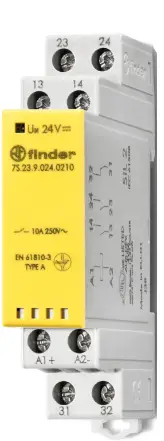
The product is a relay with the model number 7S.xx. It has various variations such as 7S.23, 7S.xx.8.xxx.xxx0, and 7S.xx.9.xxx.xxx0. The relay can operate at different voltage ranges for both AC and DC power sources.
- 7S.xx.8.xxx.xxx0: AC voltage range is between Umin – Umax (195…264)V AC and DC voltage range is between Umin – Umax (93.5…137.5)V AC.
- 7S.xx.9.xxx.xxx0: DC voltage ranges are as follows: Umin – Umax (9.6…14.4)V DC, Umin – Umax (16.8…30)V DC, and Umin – Umax (77…137.5)V DC.
- 7S.23.9.xxx.0210: DC voltage ranges are as follows: Umin – Umax (9.6…14.4)V DC, Umin – Umax (19.2…28.8)V DC, Umin – Umax (38.4…57.6)V DC, and Umin – Umax (88…132)V DC.
The relay has various load capacities and specifications depending on the model number. It can handle different current ratings, power factors, and probabilistic constraints.
Product Usage Instructions
- Ensure that the power source matches the specified voltage range for the relay model you are using.
- Connect the load to the relay using appropriate wiring based on the load specifications.
- If using AC power, make sure to connect the relay according to the AC1 and AC15 specifications.
- If using DC power, refer to the DC1 and DC13 specifications for proper connection.
- Check the load capacity and current rating of the relay to ensure it can handle the connected load. Refer to the product manual for specific values.
- Follow the provided safety guidelines and precautions while operating the relay.
- In case of any issues or faults, refer to the diagnostic features and contact the manufacturer for further assistance.
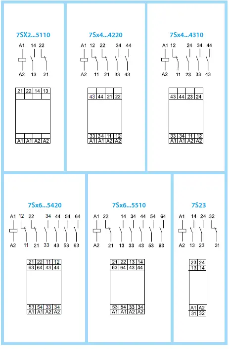
WIRING
| 7S.xx.8.xxx.xxx0 230 Umin – Umax (195…264)V AC 120 Umin – Umax (93.5. 137.5)V AC | 7S.xx.9.xxx.xxx0 012 Umin – Umax (9.6. 14.4)V DC 024 Umin – Umax (16.8. 30)V DC 110 Umin – Umax (77. 137.5)V DC | 7S.23.9.xxx.0210 012 Umin – Umax (9.6. 14.4)V DC 024 Umin – Umax (19.2. 28.8)V DC 048 Umin – Umax (38.4. 57.6)V DC 110 Umin – Umax (88. 132)V DC | |||
| P 2.3 VA (50 Hz) / 1 W | |||||
| 6 A 250 V AC | 10 A 250 V AC | ||||
| AC1 | 1500 VA | AC1 | 2500 VA | ||
| AC15 (230V) | 3 A | AC15 (230 V) | 5 A | ||
| DC1 (30/110/220)V | (6/0.6/0.2) A [7S.x2] | DC1 (30/110/220)V | (6/0.6/0.2)A | ||
| (6/0.9/0.3) A | |||||
| DC13 (24V) | 1 A [7S.x2] | DC13 (24 V) | 5 A | ||
| 3 A [7S.x4] | |||||
| 3 A [7S.x6] | |||||
| (–40…+70)°C | |||||
| IP20 | |||||
PRODUCT SPECIFICATIONS
| Relay | Load | Vn (V) | In (A) | PFD | PFH | T cycle (s) | B10d | DC avg/SIL |
|
7S.12/32…5100 (T) | AC1 | 250 V AC | 6 | 5.21E- 04 | 5.21E- 08 | 180 | 220.000 | 90%/SIL2 |
| 4 | 4.88E- 04 | 4.88E- 08 | 120 | 350.000 | 90%/SIL2 | |||
| DC13 | 24 V DC | 1 | 2.02E- 04 | 2.02E- 08 | 450 | 210.000 | 90%/SIL2 | |
| AC15 | 250 V AC | 1 | 3.29E- 04 | 3.29E- 08 | 240 | 250.000 | 90%/SIL2 | |
| 2 | 7.51E- 04 | 7.51E- 08 | 180 | 160.000 | 90%/SIL2 | |||
| 3 | 1.42E- 03 | 1.42E- 07 | 180 | 85.000 | 90%/SIL2 | |||
|
7S.14/7S.34…4220 (T) 7S.14/7S.34…4310 (T) | DC13 | 24 DC | 3 | 8.00E- 03 | 8.00E- 07 | 100 | 450.000 | 90%/SIL2 |
| 1 | 6.00E- 03 | 6.00E- 07 | 30 | 2.000.000 | 90%/SIL2 | |||
| 0,75 | 6.00E- 03 | 6.00E- 07 | 30 | 2.000.000 | 90%/SIL2 | |||
| AC15 | 250 V AC | 3 | 1.50E- 03 | 1.50E- 07 | 600 | 400.000 | 90%/SIL2 | |
| 0.1 | 1.20E- 03 | 1.20E- 07 | 30 | 10.000.000 | 90%/SIL2 | |||
| AC1 | 250 V AC | 6 | 1.20E- 03 | 1.20E- 07 | 600 | 500.000 | 90%/SIL2 | |
| 4 | 1.00E- 03 | 1.00E- 07 | 600 | 600.000 | 90%/SIL2 | |||
| 2 | 1.20E- 03 | 1.20E- 07 | 300 | 1.000.000 | 90%/SIL2 | |||
|
7S.16/7S.36…5420 (T) 7S.16/7S.36…5510 (T) | DC13 | 24 V DC | 3 | 4.00E- 03 | 4.00E- 07 | 300 | 300.000 | 90%/SIL2 |
| 2 | 6.00E- 03 | 6.00E- 07 | 30 | 2.000.000 | 90%/SIL2 | |||
| 1 | 1.71E- 03 | 1.71E- 07 | 30 | 7.000.000 | 90%/SIL2 | |||
| AC15 | 250 V AC | 3 | 5.22E- 03 | 5.22E- 07 | 300 | 230.000 | 90%/SIL2 | |
| 1 | 3.16E- 03 | 3.16E- 07 | 300 | 380.000 | 90%/SIL2 | |||
| AC1 | 250 V AC | 6 | 2.40E- 03 | 2.40E- 07 | 300 | 500.000 | 90%/SIL2 | |
| 4 | 1.40E- 03 | 1.40E- 07 | 300 | 860.000 | 90%/SIL2 | |||
| 2 | 9.23E- 03 | 9.23E- 07 | 30 | 1.300.000 | 90%/SIL2 | |||
| 7S.23/7S.P3…0210 (T) | DC13 | 24 V DC | 5 | 2.00E- 03 | 2.00E- 07 | 300 | 600.000 | 90%/SIL2 |
| AC15 | 230 V AC | 5 | 1.33E- 03 | 1.33E- 07 | 300 | 900.000 | 90%/SIL2 |
| Probabilistic constraints | |
| T1 | 1 year |
| MTTR | 8h |
| MTR | 0.5 h |
| PFD* | 1E5 x PFH |
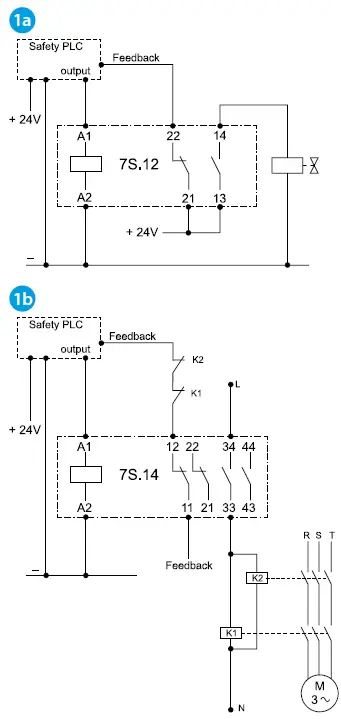
Modular relays with mechanically linked guided contacts
- Direct load switching and diagnostic contact – common power supply
- Indirect load switching and diagnostic contact – different voltages
Relays with guided contacts mechanically linked for application of safety up to SIL 2. As a single-channel (1oo1) system, the diagnostic function is entrusted to a safety automaton intended for fault detection before the safety function is required. No dynamic test is planned or imposed by the manufacturer. If the NO contact does not open when the relay coil is no longer supplied, the NC contact must not close in order to prevent the reboot the machine. The use of relays as a device for the realization a safety function, requires that the electrical circuit be complies with the standards in force concerning the applications of security. The NO contact of the relay must cut off the power supply to the load when the relay coil is no longer powered. With this principle, the closing fault of the NO contact is a fault while the opening fault is a dangerous fault. The system is designed with 1oo1 logic provides a T1 interval as trial evidence. It is assumed that the time to restart the system after a dangerous failure, is equal to MTTR and the time to perform the replacement of the 7S, is equal to MTR. Considering that the call frequency “of the safety function” must not exceed 1.14 years (10000 hours)
Installation tips
- It is recommended to install a protection device against surges (SPD) to protect safety devices
- It is recommended to install a protection device against overcurrent to protect the switched load
- Check that the degree of protection (IP) of the electrical cabinet in which the 7S series relay is suitable for the application.
Utility Model – IB7S00XXX0VXX – 12/22 – Finder S.p.A. con unico socio – 10040 ALMESE (TO) – ITALY


