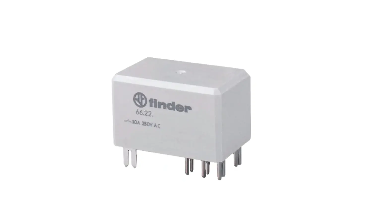
finder 66 Series Power Relays 30A
GENERAL SAFETY INFORMATION
These safety instructions refer to the installation, utilization and maintenance of 66 series relays to be used in potentially explosive areas due to the presence of combustible GAS.
The information of these instructions are only for qualified personnel. The relays comply with the Essential Health and Safety Requirements applicable for ATEX Components, for potentially explosive atmospheres provided by European Standards: EN 60079-0 (2012+A11/2013), EN 60079-15 (2010)
TRANSPORT, STORAGE
On receipt verify that the relay has not been damaged during transport. If damaged, do not install and immediately advise the transport service.
INSTALLATION
Installation must comply with the rules of the standard EN 60079-14 or with the current national standards.
Before the installation in an explosive atmosphere, the installer must ensure that the relay is suitable for the classified area in consideration of the different inflammable substances present in the installation area (please verify the marking on the relay cover before installation).
The relay must be installed only by qualified people with knowledge of electrical apparatus for explosive gas atmospheres and electrical installations in hazardous areas and has to be done with the relay and equipment at standstill, electrically dead and locked against restart.
MARKING
| Specific marking of explosion protection | |
| II Component for surface plant (different from mines) | |
| 3 Category 3: normal level of protection | |
|
GAS | G explosive atmosphere due to presence of combustible gas vapour or mist |
| Ex nC Sealed device (type of protection for category 3G) | |
| IIC Gas group | |
| Gc Equipment Protection Level | |
| −40°C ≤ Ta ≤ +70°C Ambient temperature | |
| EPTI 17 ATEX 0299 U EPTI: laboratory which issues the CE type certificate 17: year of issue of certificate 0299: number of CE type certificate | |
| U: Ex component | |
ELECTRICAL CHARACTERISTICS
66.22/66.82.x.xxx.xxx3
CHARACTERISTICS OF CONTACTS
- Rated current/maximum peak current A: 25/50 (NO) −10/20 (NC)
- Rated voltage/maximum switching voltage V AC: 250/400
- Rated load-Category AC1 VA: 6250 (NO)−2500 (NC)
- Rated load-Category AC15 VA: 1200 (NO)
- Capacity for single phase motor (230V AC) kW: 1.5 (NO)
- Breaking capacity-Category DC1: 30/110/220 V A: 25/0.7/0.3 (NO)
CHARACTERISTICS OF COIL
- Rated Voltage UN V AC (50/60 Hz): 6, 12, 24, 110/115, 120/125, 230, 240
- Rated Voltage UN V DC: 6, 12, 24, 110, 125
- Rated Power AC/DC VA (50 Hz)/W: 3.6/1.7
- Operating range AC/DC: (0.8…1.1) UN
GENERAL CHARACTERISTICS
- Ambient temperature °C: −40…+70
66.22….S
Use Dual layer pcb (dimensions mm). The tracks on both sides must meet the minimum Cu cross-section as stipulated in section 6 .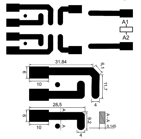
66.82
Retention force (push/pull) EN 61210: 96/88 N.
Insertion/Disconnection force (after six disconnections) EN 61210: 80/18 N.
Wiring cross section as stipulated in section 6 .
Utility Model-IB6622001- 01/18 FINDER S.p.A. con unico socio 10040 – ALMESE (TO) – ITALY


