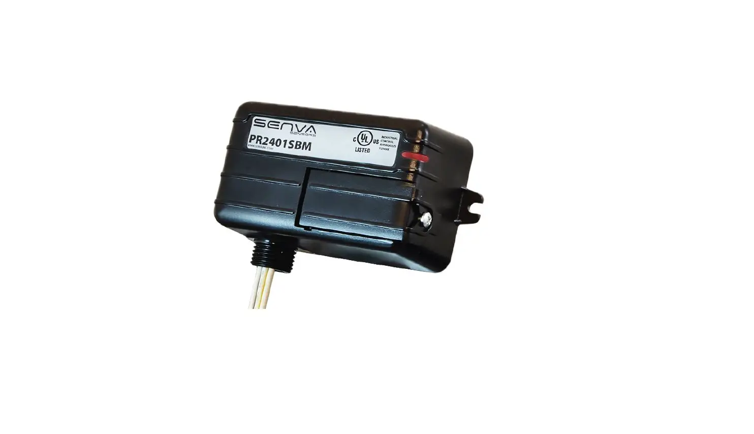
SENVA PR24 Series Power Relay
DANGER
FAILURE TO FOLLOW THESE INSTRUCTIONS MAY RESULT IN DEATH OR OTHER SERIOUS INJURY
- Follow ALL requirements in NFPA 70E for safe work practices and for Personal Protective Equipment (USA) and other applicable local codes when installing this product.
- Only qualified electrical personnel should install this product.
- Read, understand, and follow all instructions thoroughly.
- Install only on insulated conductors.
- Lock out and tag out all power sources prior to installation or working on equipment.
- Use properly rated voltage sensing instrument to determine no voltAutomated equipment may start without warningDANGERWARNING!Hazard of electrical shock, explosion, and arc flash
WARNING
IMPORTANT WARNINGS
- Equipment monitored/operated by this device may start without warning. Keep clear of apparatus at all times
- Only qualified trade installers should install this product
- This product is not intended for life-safety applications
- Do not install in hazardous or classified locations
- The installer is responsible for all applicable codes
- This product must be installed in a suitable electrical enclosure.
Automated equipment may start without warning
PRODUCT APPLICATION LIMITATION:
Senva products are not designed for life or safety applications. Senva products are not intended for use in critical applications such as nuclear facilities, human implantable device or life support. Senva is not liable, in whole or in part, for any claims or damages arising from such uses.
INSTALLATION
Disconnect, lock out and tag out all power supplies during installation
- This device shall be installed on an enclosure via a 1/2” NPT nipple.
- Secure relay to enclosure by screwing the provided con-duit nut to the 1/2” NPT nipple threads.
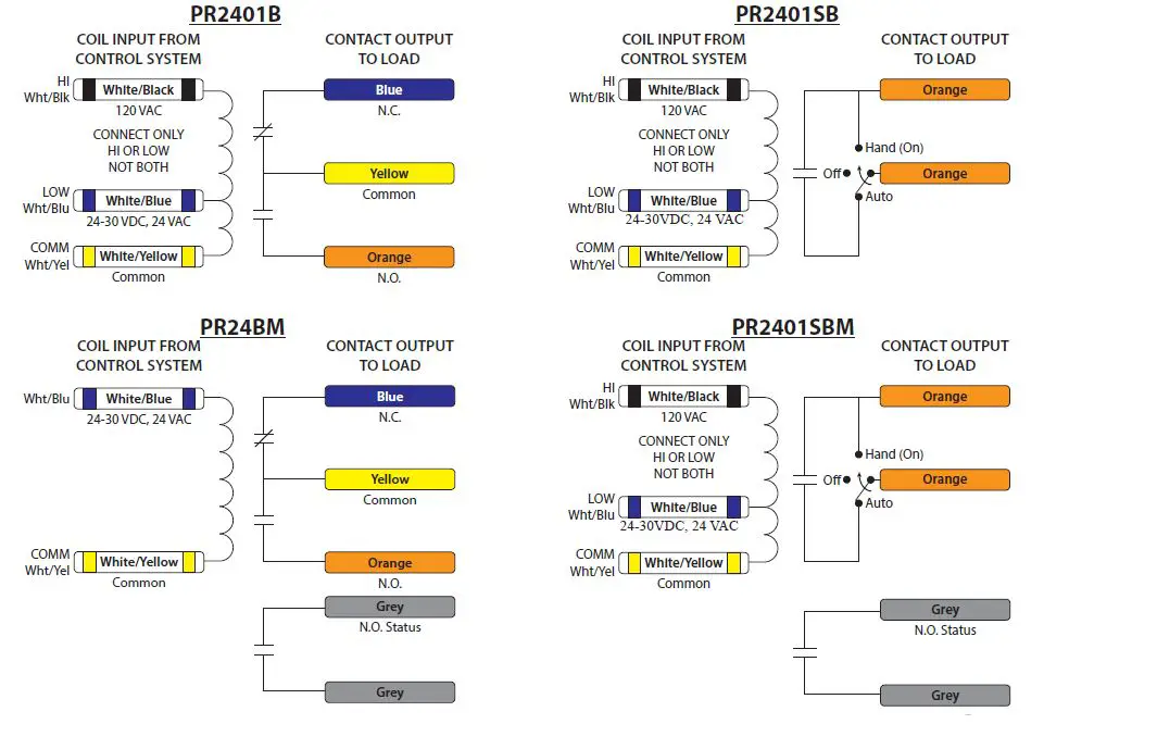
- Connect relay coil to control system by connecting the common (white and yellow conductor) to the control systems common or negative (-) terminal. Then choose either the High (white and black conductor, 120VAC) or Low (white and blue conductor, 24-30VDC/24VAC) depending on control sys-tem voltage being sent to the relay coil and connect to posi-tive (+) terminal of the control system. For the PR24BM relay, there is only a Low connection available (24-30VDC/24VAC)
- Connect relay contact wires to the application load being controlled by this relay. This will differ between SPDT and SPST contact arrangements. See wiring diagrams at the end of this guide.
- For relays with status output (PR24BM and PR2401SBM), connect (gray conductors) to control system terminals that will be monitoring status of application load.
- For relays with the Hand/Off/Auto (HOA)(PR2401SB and PR2401SBM) switch, leave switch in AUTO to control applica-tion load from control system driving relay coil. Put HOA in HAND to bypass control system and turn on application load. Putting the switch in OFF will not allow application load to turn on. You can use a M3-0.5 size screw to secure the HOA door closed.
| MODEL | CONTACT COIL INPUT | HOA | CURRENT RUN STATUS | ENCLOSURE | LED |
| PR2401B | SPDT 24-30VDC, 24VAC, 120VAC 20A | Small | = | ||
| PR24BM | SPDT 24-30VDC, 24VAC 20A | N.O. 1A @ 30VAC/DC, 0.3A TRIP | Small | = | |
| PR2401SB | SPST N.O. 24-30VDC, 24VAC, 120VAC 20A | = | Medium | = | |
| PR2401SBM | SPST N.O. 24-30VDC, 24VAC, 120VAC 20A | = | N.O. 1A @ 30VAC/DC, 0.3A TRIP | Medium | = |
| PR2401B | PR2401SB | ||||
| COIL INPUT FROM CONTACT OUTPUT CONTROL SYSTEM TO LOAD | COIL INPUT FROM CONTROL SYSTEM | CONTACT OUTPUT TO LOAD |
- senvainc.com. 1-866-660-8864
- (F)1-503-296-2529 9290 SW
- Nimbus Ave. Beaverton Oregon 97008
- Revised: 04/18/2022
- Document #152-0416


