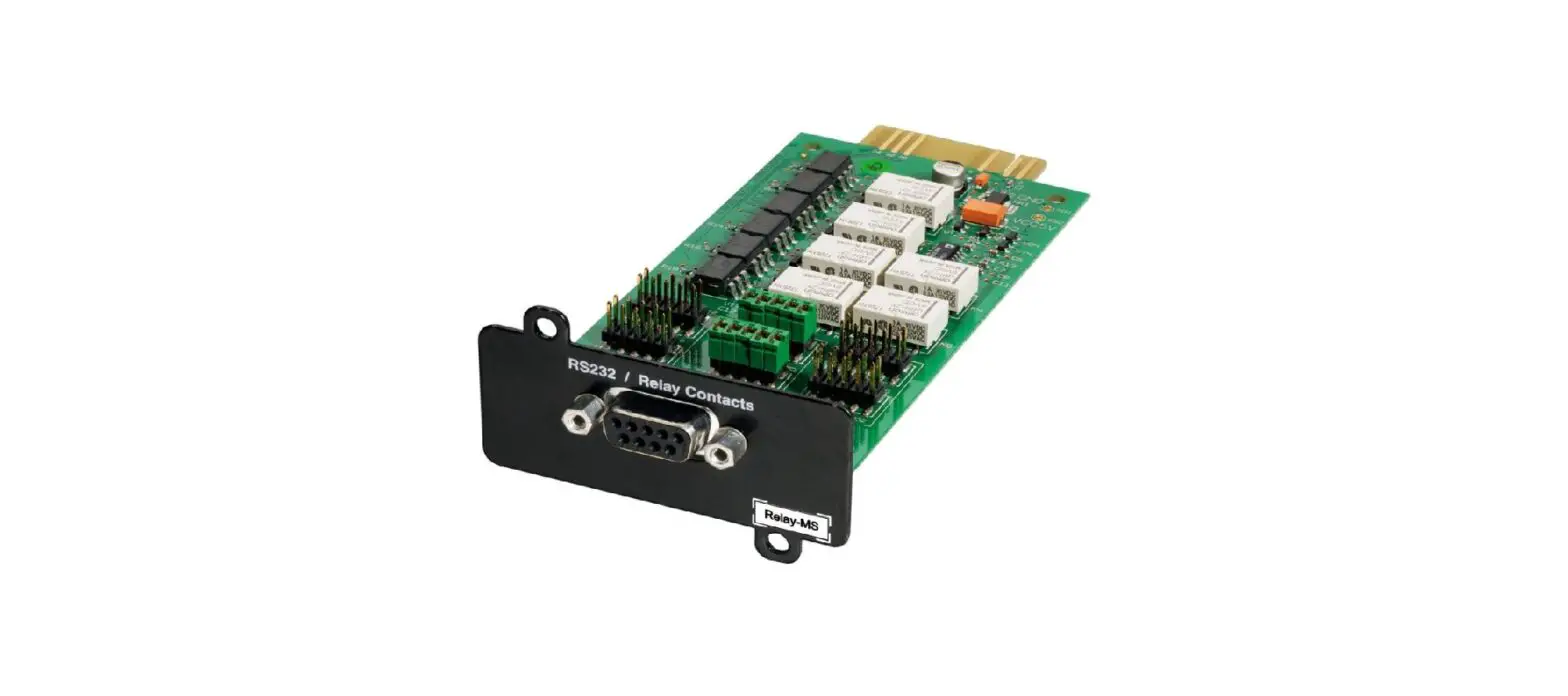
EATON 777387 Relay MS Card
USING THE CARD WITH A SINGLE-PHASE UPS
INTRODUCTION
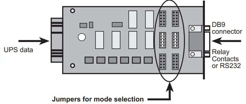
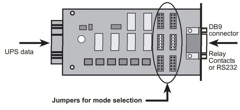
The Relay Card – MS offers two types of interfaces via a DB9 connector:
- Dry contacts (contact mode)
- RS232 serial interface (RS232 mode)
All UPSs from EATON equipped with a Mini slot can be connected to a number of electrical-management applications. Jumpers are used to select the interface (contacts or RS232).
APPLICATIONS
Contact mode (factory setting)
- In this mode, the card provides a simple way to remote UPS information to an alarm system, PLC, or computer system via dry contacts (relay).
- The transmitted information is load powered, load on bypass, load on the battery, load on utility, battery fault, and low battery.
- A UPS power-off function activated by an external contact or voltage level is also proposed. It is available only in contact mode.
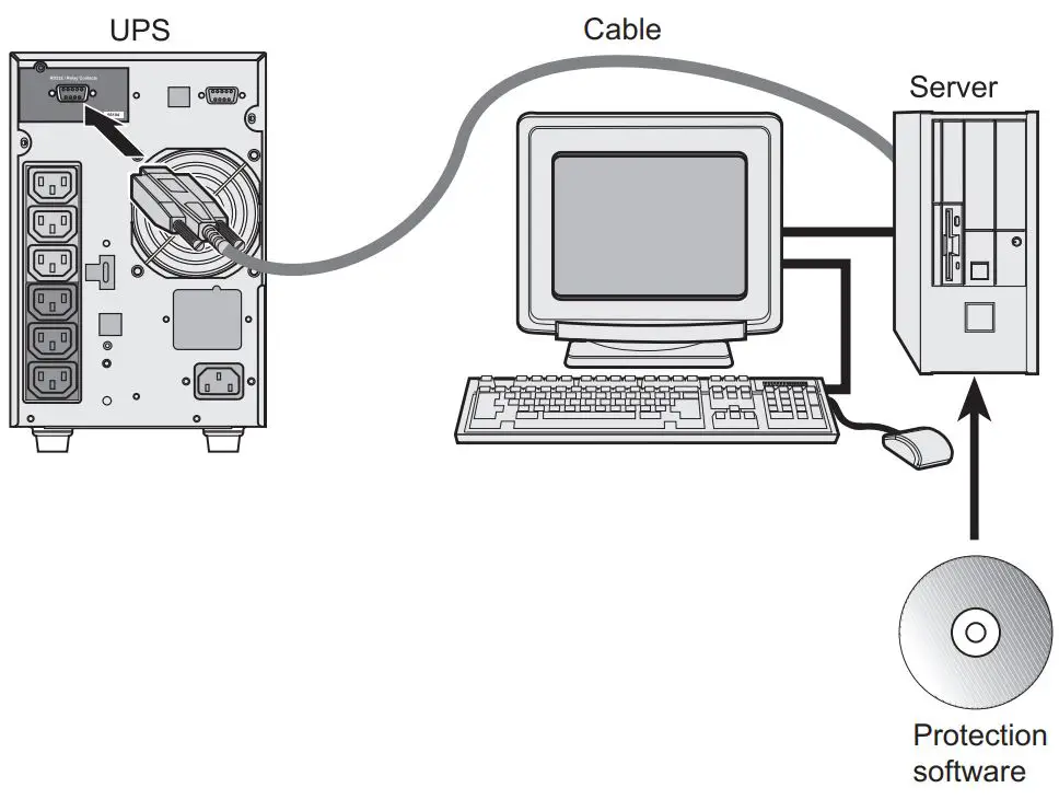
- Equipped with an IBM iSeries or Windows cable available from EATON, the card offers direct communication with the power management system of the servers supplied by the UPS and can thus provide protection (shutdown) on the reception of one of the information signals. Configuration of the various systems is presented in the documents supplied with the cable. For this application, use the Config2 setting on the card.
RS232 mode
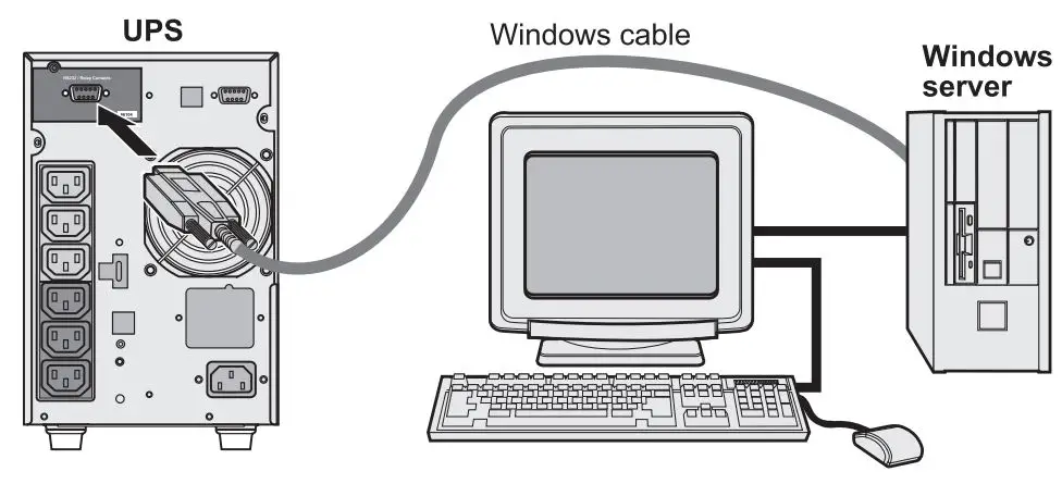
- In this mode, the card offers an RS232 interface for connection to a PC. Connection to a PC requires the RS232 UPS Communication Cable. The cable is not supplied with the card. Once connected the protection software can be installed and used immediately.
- The WindowsTM Plug&Play function is managed by the card.
- The cable is available from EATON.
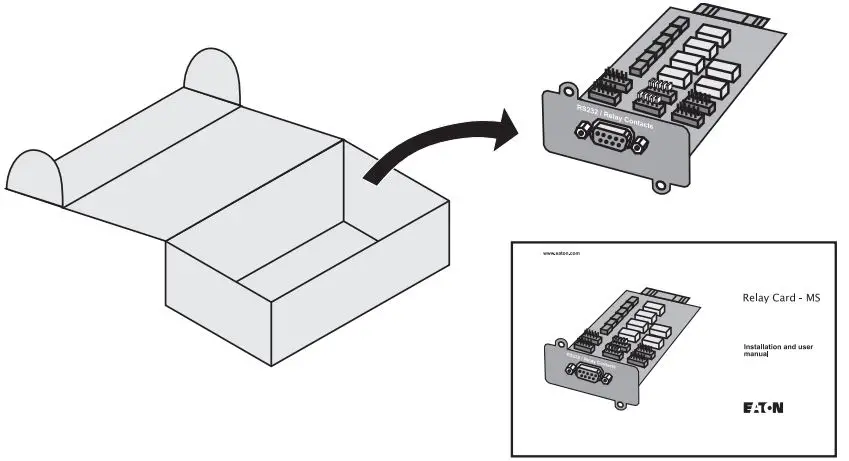
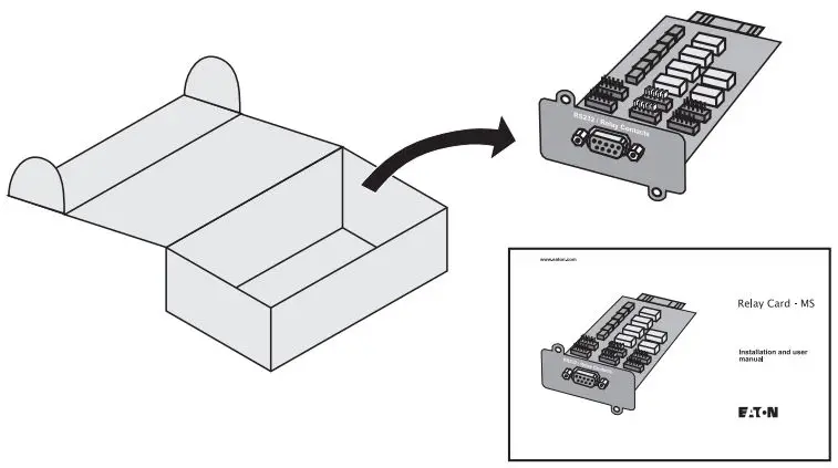
UNPACKING AND CHECKS
- One Relay Card – MS
- One installation manual (34003907)
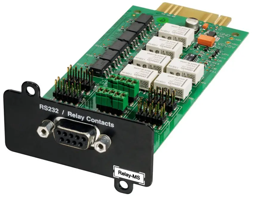
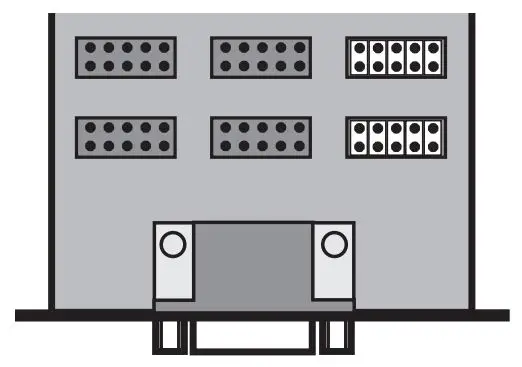
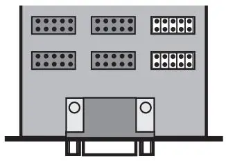
OVERVIEW
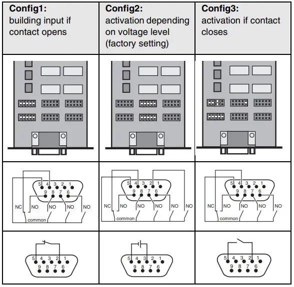
CONTACT MODE CONFIGURATION
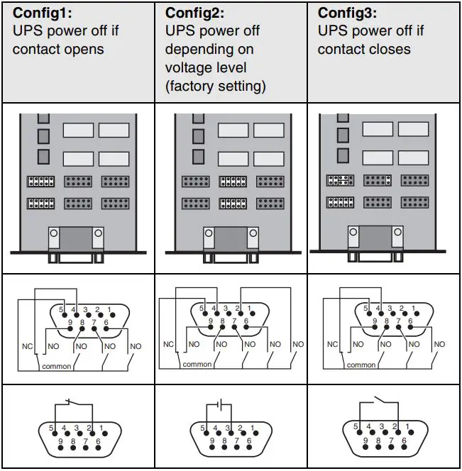
- In this mode, the contact (relay) is closed between the common (pin 5) and the pin transmitting the signal (pin 2, 4, 6, 7, 8, 9) when UPS information is active or true.
- When the card is not supplied, all the contacts between pin 5 and the other pins are open, except the contact between pin 4 and pin 5, which remains closed.
- Three configurations are available in this mode, for three types of UPS power off. The diagram below shows, for each configuration, the jumper settings, the various contacts (card not supplied), and the external wiring for the power-off function. The UPS shuts off if the contact position is the opposite of that shown.
DB9 CONNECTOR PINOUTS
| No. | Function | Description |
| 1 | Not used | |
| 2* | Battery fault (Config 2) UPS power off (Config 1 or 3) | Config 2: a battery fault occurred. Config 1 or 3: UPS power off by contact. |
| 3 | UPS power off (Config 2) Not used (Config 1 or 3) | Config 2: UPS power off by voltage level. |
| 4 | Load on utility** | The load is protected. The UPS supplies the load using utility power (not from the battery). |
| 5 | Common | Config 2: volt-free pin. Config 1 or 3: pin connected to GND. |
| 6 | Load on automatic bypass*** | The load is not protected. The UPS supplies the load using utility power. If utility power fails, the load will not be supplied. |
| 7 | Low battery | The battery has dropped below the preset warning level (depending on UPS setup). If the voltage level continues to drop, the UPS will no longer be capable of supplying power to the load. |
| 8 | UPS ON, load powered | The UPS is operational and can supply power to the load, whether utility power is available or not, whether the UPS is on the bypass or not. |
| 9 | Load on battery ** | The load is protected. The UPS supplies the load from the battery (not using utility power). |
The function of this pain varies, depending on the configuration. The Battery fault information is available only in Config 2.
- Load on utility and Load on the battery are complementary signals. They cannot be activated simultaneously.
- Not available online-interactive UPS. No manual bypass.
RS232 MODE CONFIGURATION
- In this mode, only one configuration is possible
DB9 CONNECTOR PINOUTS
| No. | Function | Description |
| 2 | TD | Transmit data (output) |
| 3 | RD | Receive data (input) |
| 5 | GND | Ground |
| 6 | RTS | Plug-&-Play (input) |
| 1, 4, 7, 8, 9 | Not used |
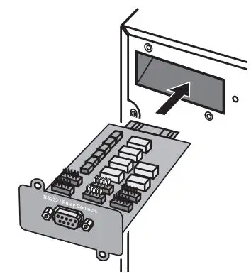
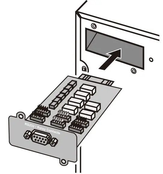
INSTALLATION
The Relay Card – MS can be installed on a running UPS from EATON compatible with this card. It is not necessary to shut off the UPS, disconnect the load, or restart the UPS.
- Remove the plastic cover of the Mini slot.
- Insert and secure the card with the screws.
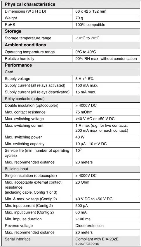
TECHNICAL SPECIFICATIONS
| Physical characteristics | |
| Dimensions (W x H x D) | 66 x 42 x 132 mm |
| Weight | 70 g |
| RoHS | 100% compatible |
| Storage | |
| Storage temperature range | -10°C to 70°C |
| Ambient conditions | |
| Operating temperature range | 0°C to 40°C |
| Relative humidity | 90% RH max. without condensation |
| Performance | |
| Card | |
| Supply voltage | 5 V +/- 5% |
| Supply current (all relays activated) | 150 mA max. |
| Supply current (all relays deactivated) | 15 mA max. |
| Relay contacts (output) | |
| Double insulation (optocoupler) | > 4000V DC |
| Max. contact resistance | 75 mOhm |
| Max. switching voltage | <40 V AC or <50 V DC |
| Max. switching current | 1 A max (e.g. for five contacts, 200 mA max for each contact.) |
| Max. switching power | 40 W |
| Min. switching capacity | 10 µA 10 mV DC |
| Service life (min. number of operating cycles) | 105 |
| Max. recommended distance | 20 meters |
| UPS power off (input) | |
| Single insulation (optocoupler) | > 4000V DC |
| Max. acceptable external contact resistance (including cable, Config 1 or 3) | 20 Ohm |
| Min. & max. voltage (Config 2) | +3 V DC to +50 V DC |
| Min. input current (Config 2) | 500 µA |
| Max. input current (Config 2) | 60 mA |
| Min. impulse duration | >100 ms |
| Reverse voltage | Diode protection |
| Max. recommended distance | 20 meters |
| Note. The UPS does not take into account the shutdown time required by any protected applications once the shutoff order has been requested. Power at the UPS outputs is interrupted immediately (<100 ms). | |
| Serial interface | Compliant with EIA-232E specifications |
SAFETY INSTRUCTIONS
The relay contacts and the card inputs are galvanically isolated from the UPS. It is strictly forbidden to apply a voltage greater than 40 V AC or 50 V DC to the contacts. Disregard for this restriction may endanger human life, damage equipment and cancel the manufacturer warranty.
ELECTROMAGNETIC COMPATIBILITY
When correctly installed and used in accordance with manufacturer instructions, the card complies with the following standards:
- ITE (Information Technology Equipment) safety: IEC/EN 60950-1 2005
- EMC: EN 61000-6-2 (2002), EN 61000-6-3 (2002), IEC/EN 62040-2 (2002)
In compliance with European directives:
- Low voltage: 73/23/EEC and 93/68/EEC.
- EMC: 89/336/EEC and 93/68/EEC.
Federal Communication Commission (FCC) statement
This equipment has been tested and found to comply with the limits for a Class B digital device, pursuant to part 15 of the FCC rules. These limits are designad to provide reasonable protection against harmful interference when the equipment is operated in a commercial environment.
USING THE CARD WITH A THREE-PHASE UPS
INTRODUCTION
The Relay Card – MS offers two types of interfaces via a DB9 connector:
- Dry contacts (contact mode)
- RS232 serial interface (RS232 mode)
All UPSs from EATON equipped with a Mini slot can be connected to a number of electrical-management applications. Jumpers are used to select the interface (contacts or RS232).
APPLICATIONS
Contact mode (factory setting)
- In this mode, the card provides a simple way to remote UPS information to an alarm system, PLC or computer system via dry contacts (relay). Refer to your UPS manual for details of which information is provided.
- A building input function activated by an external contact or voltage level is also proposed. It is available only in contact mode.
UNPACKING AND CHECKS
- One Relay Card – MS
- One installation manual (34003907)
OVERVIEW
CONTACT MODE CONFIGURATION
- In this mode, the contact (relay) is closed between the common (pin 5) and the pin transmitting the signal (pin 2, 4, 6, 7, 8, 9) when UPS information is active or true.
- When the card is not supplied, all the contacts between pin 5 and the other pins are open, except the contact between pin 4 and pin 5, which remains closed.
- Three configurations are available in this mode, for three types of building input. The diagram below shows, for each configuration, the jumper settings, the various contacts (card not supplied) and the external wiring for the power-off function. The building input activates off if the contact position is the opposite of that shown.
DB9 CONNECTOR PINOUTS
| No. | Function | Description |
| 1 | Not used | |
| 2* | Building Alarm 5 (Config 2) Building Input (Config 1 or 3) | Config 2: Normally Open contact of Building Alarm 5. Config 1 or 3: Building Input by contact. |
| 3 | Building Alarm 5 (Config 2) Not used (Config 1 or 3) | Config 2: Building Input by voltage level. |
| 4 | Building Alarm 2** | Normally Closed contact of Building Alarm 2. |
| 5 | Common | Config 2: volt-free pin. Config 1 or 3: pin connected to GND. |
| 6 | Building Alarm 3 | Normally Open contact of Building Alarm 3. |
| 7 | Building Alarm 4 | Normally Open contact of Building Alarm 4. |
| 8 | Building Alarm 1 | Normally Open contact of Building Alarm 1. |
| 9 | Building Alarm 2** | Normally Open contact of Building Alarm 2. |
- The function of this pain varies, depending on the configuration. The Building Alarm 5 information is available only in Config 2.
- Pins 4 and 9 are complementary signals. They cannot be activated simultaneously.
- Refer to your UPS manual for details on the information provided by each building alarm and input
RS232 MODE CONFIGURATION
- In this mode, only one configuration is possible.
DB9 CONNECTOR PINOUTS
| No. | Function | Description |
| 2 | TD | Transmit data (output) |
| 3 | RD | Receive data (input) |
| 5 | GND | Ground |
| 6 | RTS | Plug-&-Play (input) |
| 1, 4, 7, 8, 9 | Not used |
INSTALLATION
The Relay Card-MS can be installed on a running UPS from EATON compatible with this card. It is not necessary to shut off the UPS, disconnect the load, or restart the UPS.
- Remove the plastic cover of the Minislot
- Insert and secure the card with the screws.
TECHNICAL SPECIFICATIONS
SAFETY INSTRUCTIONS
The relay contacts and the card inputs are galvanically isolated from the UPS. It is strictly forbidden to apply a voltage greater than 40 V AC or 50 V DC to the contacts. Disregarding this restriction may endanger human life, damage equipment and cancel the manufacturer warranty.
ELECTROMAGNETIC COMPATIBILITY
When correctly installed and used in accordance with manufacturer instructions, the card complies with the following standards:
- ITE (Information Technology Equipment) safety: IEC/EN 60950-1 2005
- EMC: EN 61000-6-2 (2002), EN 61000-6-3 (2002), IEC/EN 62040-2 (2002) In compliance with European directives:
- Low voltage: 73/23/EEC and 93/68/EEC.
- EMC: 89/336/EEC and 93/68/EEC. Federal Communication Commission (FCC) Statement This equipment has been tested and found to comply with the limits for a Class A digital device, pursuant to part 15 of the FCC rules. These limits are designed to provide reasonable protection against harmful interference when the equipment is operated in an industrial environment.
Federal Communication Commission (FCC) Statement
This equipment has been tested and found to comply with the limits for a Class A digital device, pursuant to part 15 of the FCC rules. These limits are designad to provide reasonable protection against harmful interference when the equipment is operated in an industrial environment.
WEB SITE
The information presented in this manual is also available in other languages at www.eaton.com/powerquality.
WEEE
The crossed-out wheeled bin symbol indicates that waste electrical and electronic equipment should not be discarded together with unseparated household waste, but must be collected separately. The product should be handed in for recycling in accordance with the local environmental regulations for waste disposal. By separating waste electrical and electronic equip- ment, you will help reduce the volume of waste sent for incineration or land-fills and minimize any potential negative impact on human health and the environment.


