![]()
![]()
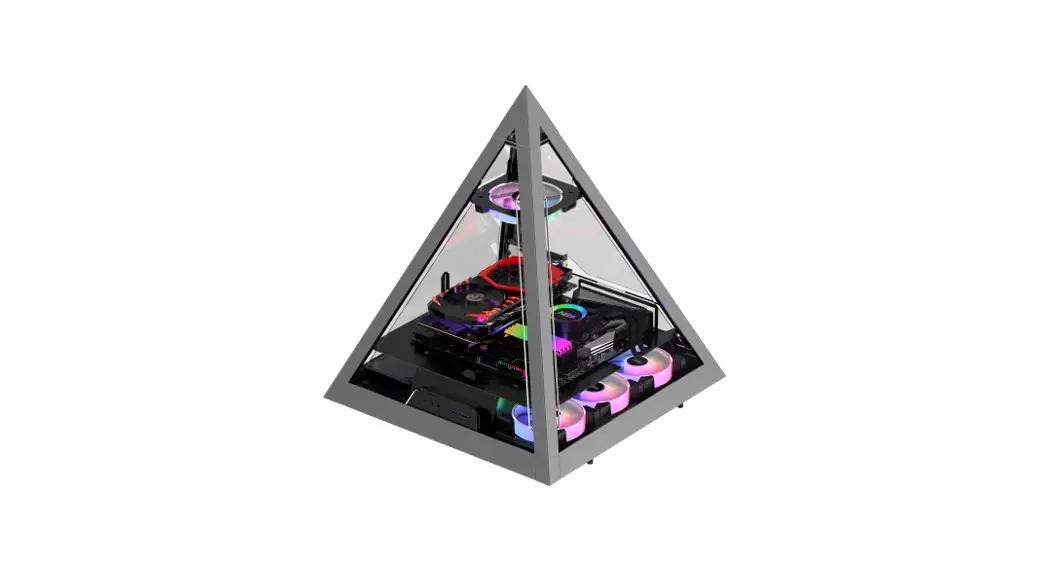
CSAZ-804V
User Manual
www.azzatek.com
Contents hide
Installation Instructions
- Specifications
- Chassis Parts
- Removing The Top Glass Panel
- Overview
- Supported Motherboards
- Power Supply Installation
- Water Radiator Installation
- 2.5″SSD / 3.5″HDD Installation
- Fan Installation
- Digital RGB Fan Installation For Motherboard
Specifications
| Model | |
| Model Name: | PYRAMID 804 |
| Name: | CSAZ-804V |
| Specifications | |
| Type: | ATX Tower |
| Color: | 1.5–2.0mm SPCC+ 2.5mm Aluminum |
| Side Panel Window: | 4 sides panel are Tempered Glass |
| Max. CPU Cooler Height: | UP to 95mm |
| Max. GPU Dimensions: | 1=280 mm / W=80 mm / H=132 mm (Vertical) |
| Power Supply: | Not Included |
| Motherboard Compatibility: | <305x280mm SSI-CEB – ATX |
| Expansion | |
| External 5.25″ Drive Bays: | 0 |
| Internal 2.5″ Drive Bays: | Up to 2 |
| Internal 3.5″ Drive Bays: | Up to 1 (Convertible with 2.5″SSDx1 ) |
| Expansion slots: | 7 |
| Front Ports: | 2xUSB 3.0 、 HD Audio 、Type C 、Metal power button |
| Cooling System | |
| fans installed: | |
| Physical Specifications | |
| Metal Chassis Dimensions (HxWxD) | 558x490x490/22×19.3×19.3 inch |
| Dimension with Case Stand(HxWxD) | 589x490x490mm/23.2×19.3×19.3 inch |
| Weight: | 14.1kg /31.1lbs |
| Features | |
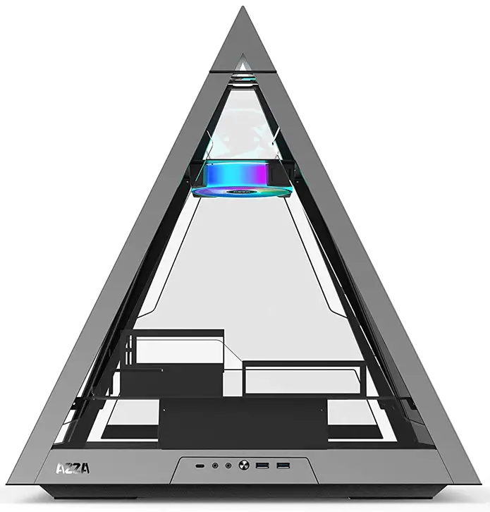
| Tempered Glass Side Window: | High-quality tempered glass side window allows for clear visuals to inner components |
| Available Fan Ports: | lx120mm Fan port in the Top(lx 120mm Hurricane II Digital RGB Fan included ) 3x120mm Fan port in the Bottom |
| Water Cooling: | Supports radiators up to 360mm on the Botton CPU Air Coolers <95mm |
| isolated chamber: | ATX Power supply inside its own isolated chamber, preventing its heat from affecting other components |
| Easy installation Cooler: | A pre-cut hole for easy installation of CPU Cooler, eliminating the need to remove the motherboard |
| Accessories | Stand & Tempered glass(optional) |
Chassis parts
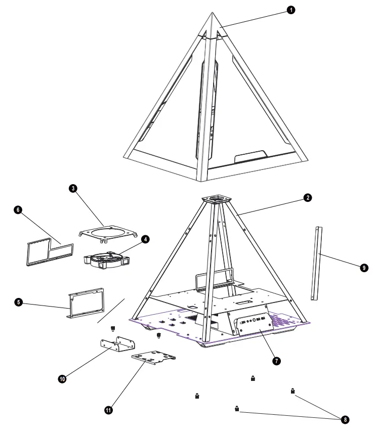
| 1 | TOP tempered glass panel cover | 7 | wo Ports: USB 3.0 x 2 , Type C, HD Audio |
| 2 | Pyramid structure | 8 | Spring bolt screw of the top panel cover |
| 3 | Fan bracket | 9 | Fan Cable management Cover |
| 4 | 12cm ARGB Fan | 10 | 2.5″SSD brackets X1 |
| 5 | Power supply rack | 11 | 3.5″HDD 12.5″SSD Spring Bolt Tray X1 |
| 6 | Vertical PCIe slot |
Removing The Top Glass Panel
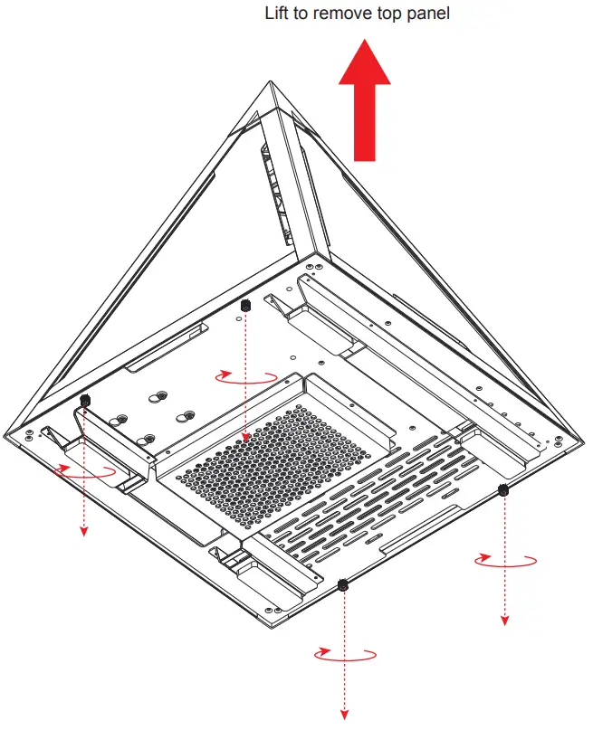
Loosen the four screws
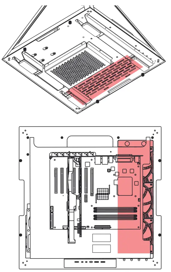
Overview
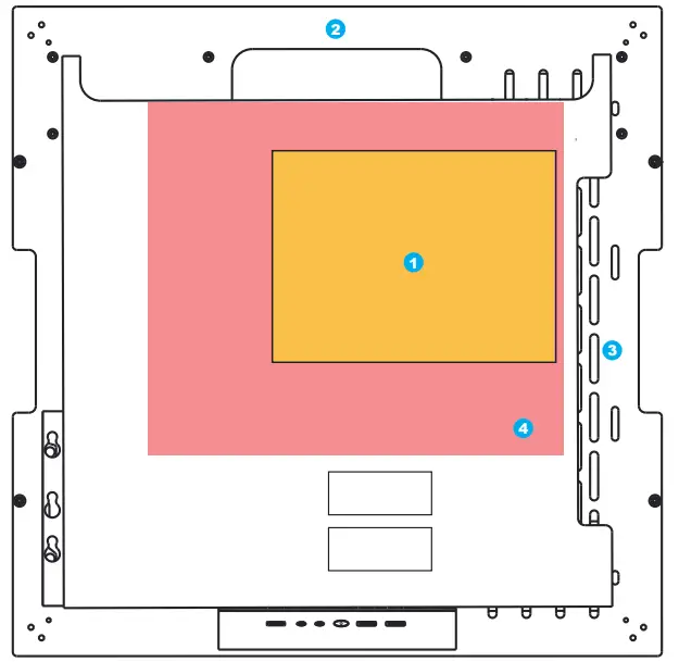
- Pre-cut hole for CPU cooling
- Power cord management hole
- Water radiator management hole
- Motherboard mount
Supported Motherboards
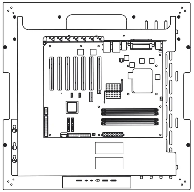
Maximum: ETX <300mm
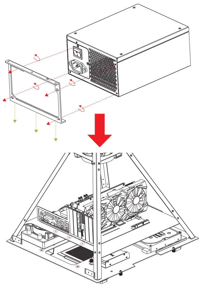
Power Supply Installation
Water Radiator Installation
Bottom View
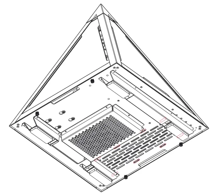
- Secure the screws of the water radiator.
Water Radiator Installation
- Supports up to 120mm fans x 3 / 240 / 360mm water radiator
2.5″SSD / 3.5″HDD Installation
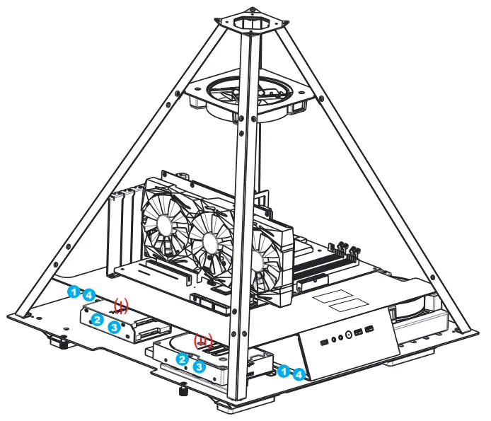
(I) 2.5″ SSD spring bolt tray: Supports up to 2.5″ SSD x 2
(II) 3.5″ HDD spring bolt tray: Supports 3.5 HDD x 1 (also compatible with a 2.5″ SSD)
STEP:
- Loosen the spring bolt screw
- Slide left or right to remove the tray.
- Install the 2.5″SSD or 3.5″HDD
- Fasten the spring bolt screw
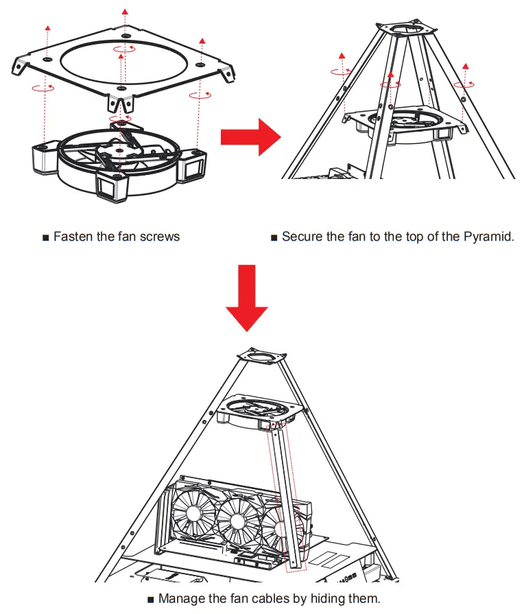
Fan Installation
Digital RGB Fan Installation For Motherboard
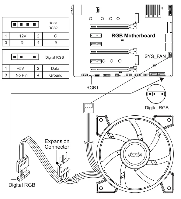
The addressable RGB fans can connect directly to the 5V addressable RGB headers of compatible motherboards, such as those from MSI™, ASUS™, Gigabyte™, and AsRock™.
Please note: Only 5V addressable headers from compatible motherboards are supported. Please do NOT connect the fan to a 12V non-addressable header.
Please check your motherboard’s specifications before use. Do not go past the motherboard’s allowed limits on power rating and LED count when connecting multiple fans/LED strips.
![]()


