Contents hide

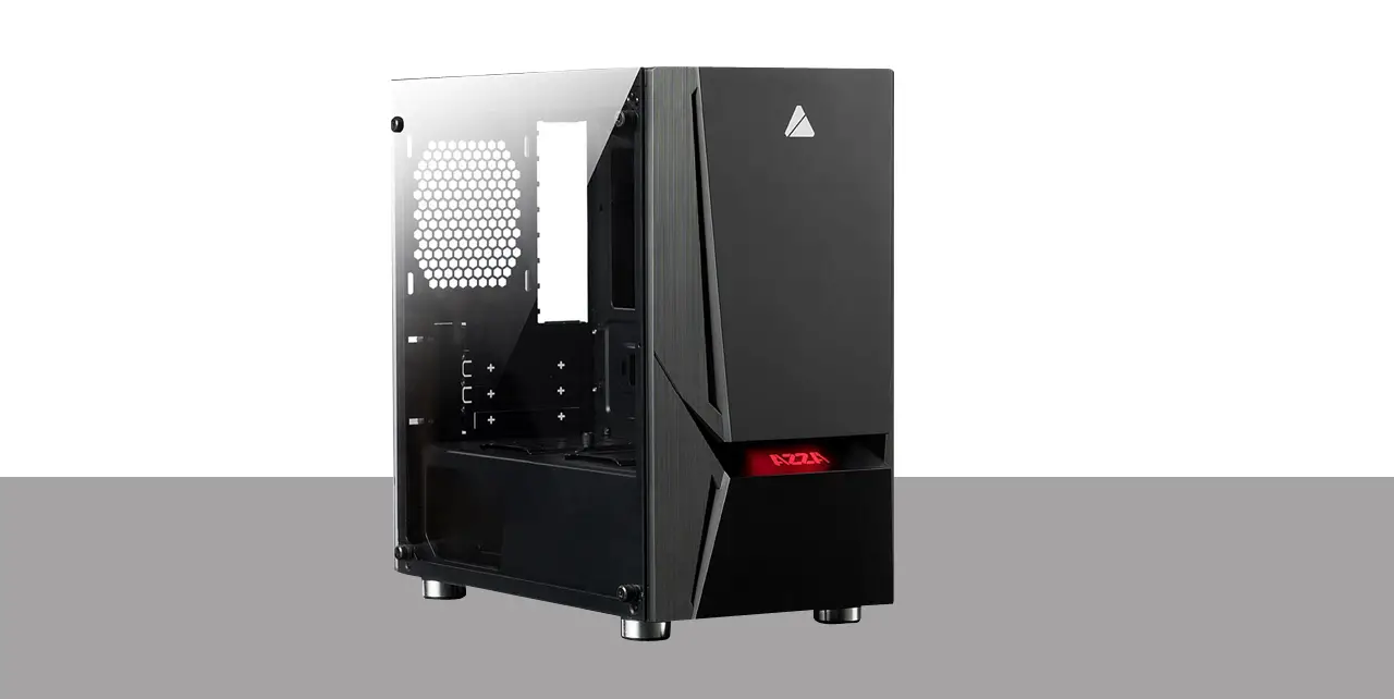
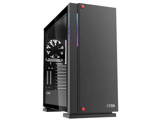
AZZA ZIRCON 7000 TG Full Tower
Specifications
| Model | |
| Model Name: | ZIRCON 7000 |
| Model Number: | CSAZ-7000 |
| Specifications | |
| Type: | ATX Full Tower |
| Color: | Black/Black(interior), White/White(interior) |
| Side Panel Window: | Tempered glass on both sides |
| Max CPU Cooler Height: | UP to 165mm |
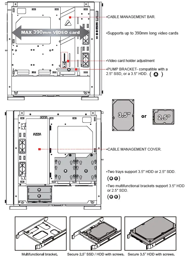
| Max Video Card Length: | Up to 390mm long video card (Horizontal/ Vertical) |
| Power Supply: | Not included |
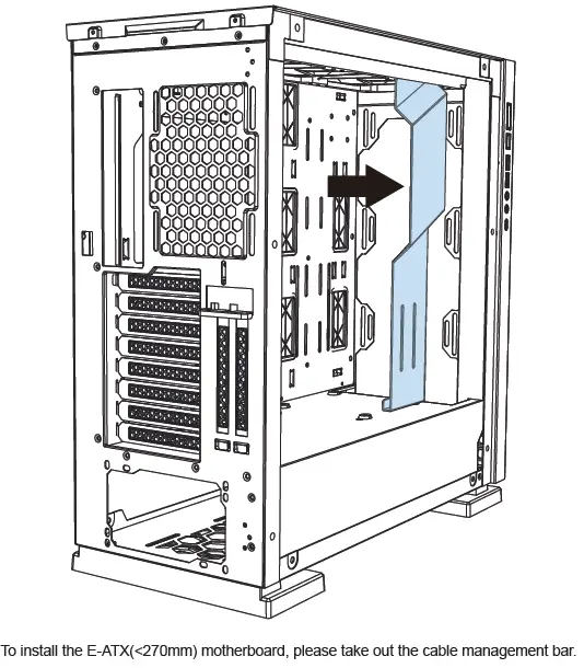
| Motherboard Compatibility: | E-ATX(<270mm)、ATX、Micro ATX |
| Expansion | |
| External 5.25″ Drive Bays: | 0 |
| Internal 2.5″ Drive Bays: | Up to 5 |
| Internal 3.5″ Drive Bays: | Up to 5 |
| Expansion Slots: | 8(Horizontal)+2(Vertical) |
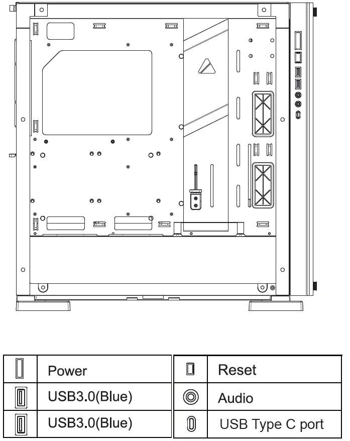
| Top Ports: | Power button, reset button, HD Audio, USB 3.0 x 2,Type C |
| Physical Specifications | |
| Case Dimensions (HxWxD): | 515 x 233 x 515mm / 20.3 x 9.2 x 20.3 inches |
| Weight: | 14.9kg /32.8lbs |
| Features | |
| Tempered Glass Sides Window: | High-quality tempered glass side window allows for clear visuals to inner components |
| Addressable RGB Light Effects: | Addressable RGB light I/O ports and strip on the front panel. All Addressable RGB light devices sync with the motherboard, allowing the motherboard software to directly control the lighting. |
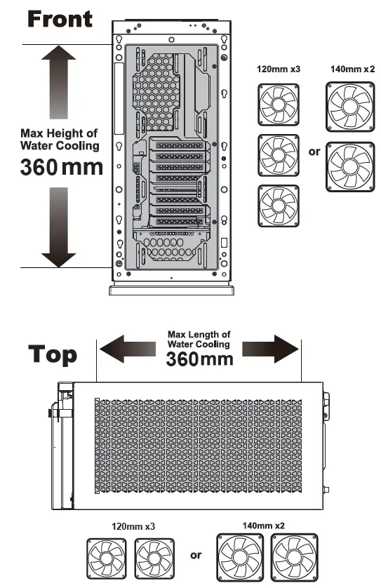
| Available Fan Ports: | 3x120mm or 2x140mm Fan ports in the front 3x120mm or 2x140mm Fan ports on the top 1x120mm Fan port in the rear (Included fan: Front – 1 x Black fan ; Rear – 1 x Black fan) |
| Water Cooling: | Supports radiators up to 280/360mm in the Front Supports radiators up to 280/360mm on the Top |
| Dust Filters: | Removable (magnetic) dustproof net on the top and front, slide-out dust filter on the bottom of chassis. |
| Power Supply Support: | Bottom mounted ATX Power Supply |
| Others Features: | Cable management bar on both sides. Can adjust the video card holder to fit your system needs. Pump bracket included, compatible with a 2.5″ SSD, or a 3.5″ HDD. |
Chassis Parts
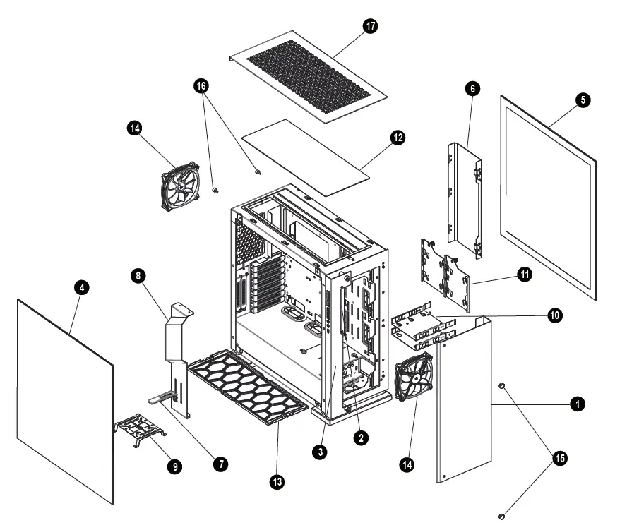
| 1 | Iron front panel |
| 2 | LED lens |
| 3 | The back panel of the front |
| 4 | Left side tempered glass panel |
| 5 | Right side tempered glass panel |
| 6 | Cable management cover |
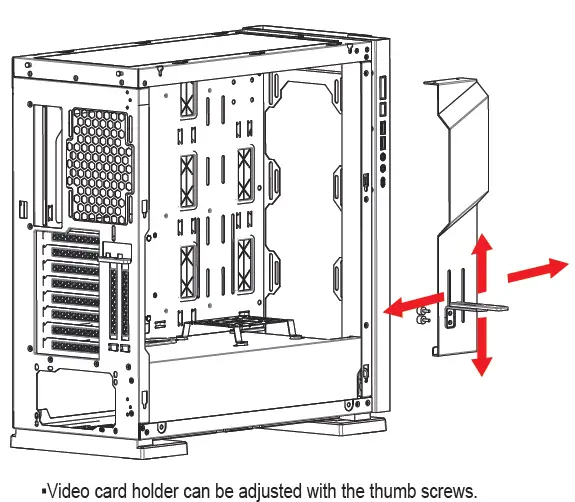
| 7 | Adjustable video card holder |
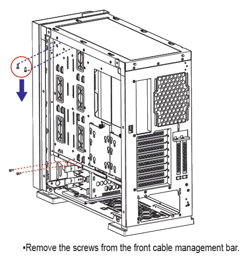
| 8 | Cable management bar |
| 9 | Pump bracket |
| 10 | 3.5″HDD/2.5″ SDD brackets x2 |
| 11 | 3.5″HDD/2.5″ SDD spring bolt tray x2 |
| 12 | Removable magnetic dustproof net |
| 13 | Slide-out dust filter |
| 14 | Black fan x2 |
| 15 | Screws for iron front panel x2 |
| 16 | Screws for iron top panel x2 |
| 17 | Iron top panel |
Control Panel Functions
Installation
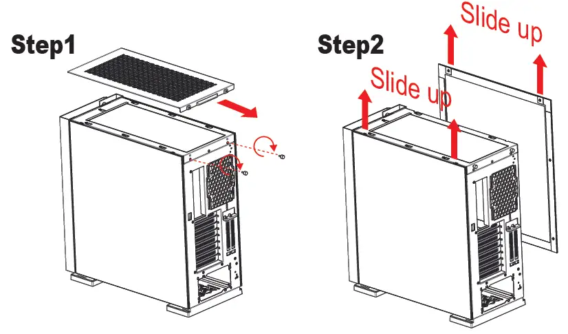
Removing the side panel
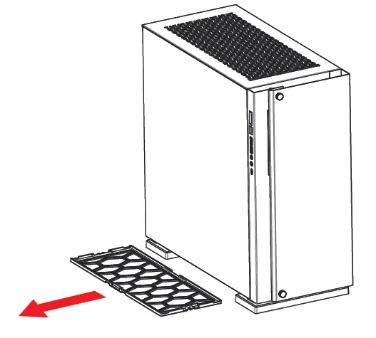
Removing the bottom dust filter
Adjusting the video card holder
Step: 1
Step: 2
3.5″ HDD /2.5″ SSD Installation
E-ATX(<270mm) motherboard Installation
Cooling System Installation
Parallel Connection (“daisy-chaining”)
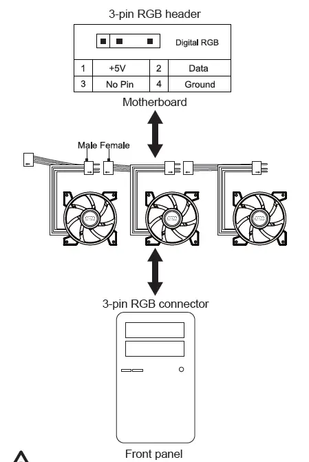
CAUTION
The addressable RGB fan has a 3-pin connector (4 holes). Please ensure that you are connecting the 3-pin connector on the fan to the 3-pin RGB header on the motherboard or RF Remote connector. Do not plug it into the 4-pin header, as the incompatible voltage will fry the fan. The 3-pin connector on the fan still has 4 holes, but the 4th hole is intentionally blocked for this reason, so please do not try to force it.


