Altronix Trove3MBK3 Enclosure/Backplane And Brackets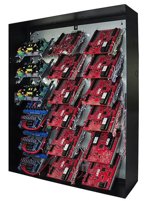
Overview
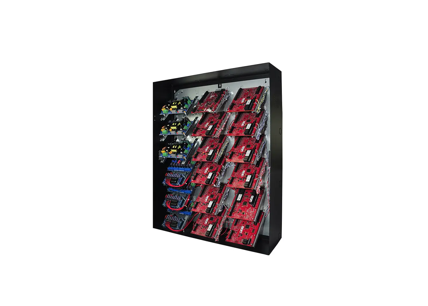
Altronix Trove3MBK3 enclosure/backplane and brackets accommodate Altronix power supply/charger(s), sub-assemblies and Mercury controllers.
Hardware and Accessories
- Two (2) tamper switches (Altronix Model TS112 or equivalent).
- Cam lock.
Mechanical
- 16 Gauge enclosure with ample knockouts for convenient access.
- Enclosure Dimensions (H x W x D): 36.12” x 30.125” x 7.06” (917.5mm x 768.1mm x 179.3mm).
Installation Instructions
Wiring methods shall be in accordance with the National Electrical Code/NFPA 70/ANSI, and with all local codes and authorities having jurisdiction.
Product is intended for indoor use only.
- Mark and predrill holes in the wall to line up with the top three keyholes in the enclosure. Install three upper fasteners and screws in the wall with the screw heads protruding. Place the enclosure’s upper keyholes over the three upper screws, level and secure.
Mark the position of the lower three holes. Remove the enclosure. Drill the lower holes and install the three fasteners. Place the enclosure’s upper keyholes over the three upper screws.
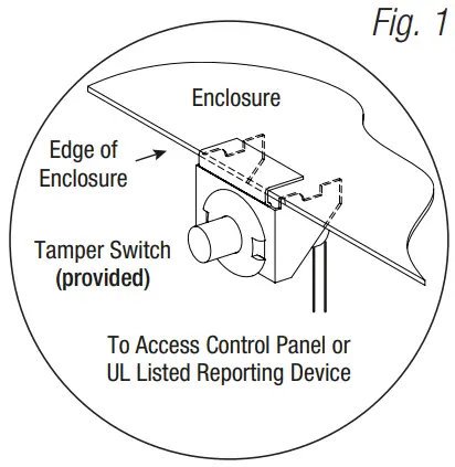
Install the three lower screws and make sure to tighten all screws. - Mount included UL Listed tamper switches (Altronix Model TS112 or equivalent) in desired location, opposite hinge. Slide the tamper switch bracket onto the edge of the enclosure approximately 2” from the right side (Fig. 1, pg. 2). Connect tamper switch wiring to the Access Control Panel input or the appropriate UL Listed reporting device. To activate alarm signal open the door of the enclosure.
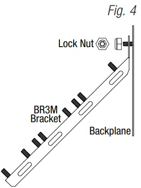
- Mount Altronix power supply/charger(s), sub-assemblies and Mercury controllers to brackets (BR3M), refer to drawings below.
- Secure BR3M brackets with boards to the backplane (TM3B) utilizing two (2) lock nuts (Fig. 5, pg. 3).
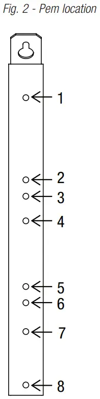
PEM Location Mercury Platform Altronix 1 LP4502, LP1502, MR16IN, MR16OUT, MR52 ACM4(CB), ACM8(CB), ACMS8(CB), LINQ8ACM(CB), LINQ8PD(CB), PD8UL(CB), PDS8(CB) 2
LP4502, LP1502, MR16IN, MR16OUT, MR52 eFlow4NB, eFlow6NB, eFlow102NB, eFlow104NB 3 ACM4(CB), ACM8(CB), ACMS8(CB), LINQ8ACM(CB), LINQ8PD(CB), PD8UL(CB), PDS8(CB) 4 LP2500, MUX8 5 ACM4(CB), LINQ8PD(CB), PD8UL(CB), PDS8(CB) 6 LP4502, LP1502, LP2500, MR16IN, MR16OUT, MR52, MUX8 7 eFlow4NB, eFlow6NB, eFlow102NB, eFlow104NB 8 LP4502, LP1502, LP2500, MR16IN, MR16OUT, MR52, MUX8 ACM4(CB), LINQ8PD(CB), PD8UL(CB), PDS8(CB)
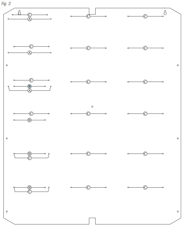
Trove3MBK3 Configuration of Altronix / LenelS2 / Mercury Platform Boards:
| Altronix / Lenel / Mercury Access Controller | Pem Mounting |
| eFlow4NB, eFlow6NB, eFlow102NB, eFlow104NB | (A) |
| ACM4, ACM4CB, ACM8, ACM8CB, ACMS8, ACMS8CB, LINQ8ACM, LINQ8ACMCB, LINQ8PD, LINQ8PDCB, PD4UL, PD4ULCB, PD8UL, PD8ULCB, PDS8, PDS8CB | (B) |
| LNL-2220, LNL-4420, LNL-1320, LNL-1100, LNL-1200, LP1502, LP4502, MR52, MR16IN, MR16OUT | (C) |
Trove3 Enclosure Dimensions (H x W x D approximate):
36.12” x 30.125” x 7.06” (917.5mm x 768.1mm x 179.3mm)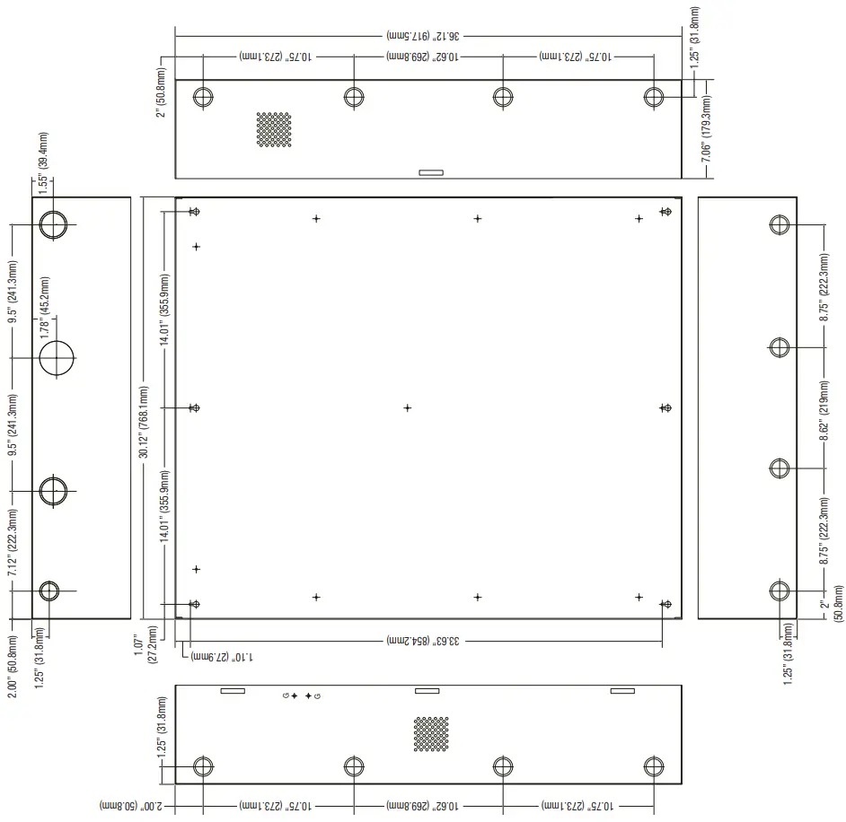
Customer Service
140 58th Street, Brooklyn, New York 11220 USA
phone: 718-567-8181
fax: 718-567-9056
web site: www.altronix.com
e-mail: [email protected]
Lifetime Warranty
IITrove3MBK3


 Installation Guide")


