![]()
Installation and Maintenance
Manual
with Safety Information and Parts List
Model SBC
Effective September 2020
Bulletin #736
RECOMMENDED SPARE PARTS HIGHLIGHTED IN GRAY
IMPORTANT!
DO NOT DESTROY
INTRODUCTION
This manual provides guidelines and procedures for installing, operating, and maintaining your conveyor. A complete parts list is provided with recommended spare parts highlighted in gray. Important safety information is also provided throughout the manual. For safety to personnel and for proper operation of your conveyor, it is recommended that you read and follow the instructions provided in this manual.
• Receiving and Uncrating
- Check the number of items received against the bill of lading.
- Examine condition of equipment to determine if any damage occurred during shipment.
- Move all crates to area of installation.
- Remove crating and check for optional equipment that may be fastened to the conveyor. Make sure these parts (or any foreign pieces) are removed.
NOTE: If damage has occurred or freight is missing, Contact your Hytrol Integration Partner.
• How to Order Replacement Parts
Included in this manual are parts drawings with complete replacement parts lists. Minor fasteners, such as nuts and bolts, are not included.
When ordering replacement parts:
- Contact Dealer from whom conveyor was purchased or nearest HYTROL Integration Partner.
- Give Conveyor Model Number and Serial Number or HYTROL Factory Order Number.
- Give complete description from Parts List.
- Give type of drive. Example—8″ End Drive, 8″ Center Drive, etc.
- If you are in a breakdown situation, tell us.
HYTROL Serial Number
(Located near Drive on Powered Models).
SAFETY INFORMATION
• Installation
GUARDS AND GUARDING
Interfacing of Equipment. When two or more pieces of equipment are interfaced, special attention shall be given to the interfaced area to ensure the presence of adequate guarding and safety devices. Guarding Exceptions. Whenever conditions prevail that would require guarding under these standards, but such guarding would render the conveyor unusable, prominent warning means shall be provided in the area or on the equipment in lieu of guarding. Guarded by Location or Position. Where necessary for the protection of employees from hazards, all exposed moving machinery parts that present a hazard to employees at their work station shall be mechanically or electrically guarded, or guarded by location or position.
- Remoteness from frequent presence of public or employed personnel shall constitute guarding by location.
- When a conveyor passes over a walkway, roadway, or work station, it is considered guarded solely by location or position if all moving parts are at least 8 ft. (2.44 m) above the floor or walking surface or are otherwise located so that the employee cannot inadvertently come in contact with hazardous moving parts.
- Although overhead conveyors may be guarded by location, spill guards, pan guards, or equivalent shall be provided if the product may fall off the conveyor for any reason and if personnel would be endangered.
HEADROOM
- When conveyors are installed above exit passageways, aisles, or corridors, there shall be provided a minimum clearance of 6 ft. 8 in. (2.032 m) measured vertically from the floor or walking surface to the lowest part of the conveyor or guards.
- Where system function will be impaired by providing the minimum clearance of 6 ft. 8 in. (2.032 m) through an emergency clearance, alternate passageways shall be provided.
- It is permissible to allow passage under conveyors with less than 6 ft. 8 in. (2.032 m) clearance from the floor for other than emergency exits if a suitable warning indicates low headroom.
• Operation
A) Only trained employees shall be permitted to operate conveyors. Training shall include instruction in operation under normal conditions and emergency situations.
B) Where employee safety is dependent upon stopping and/or starting devices, they shall be kept free of obstructions to permit ready access.
C) The area around loading and unloading points shall be kept clear of obstructions which could endanger personnel.
D) No person shall ride the load-carrying element of a conveyor under any circumstances unless that person is specifically authorized by the owner or employer to do so. Under those circumstances, such employee shall only ride a conveyor which incorporates within its supporting structure platforms or control stations specifically designed for carrying personnel. Under no circumstances shall any person ride on any element of a vertical conveyor.
E) Personnel working on or near a conveyor shall be instructed as to the location and operation of pertinent stopping devices.
F) A conveyor shall be used to transport only material it is capable of handling safely.
G) Under no circumstances shall the safety characteristics of the conveyor be altered if such alterations would endanger personnel.
H) Routine inspections and preventive and corrective maintenance
“Building Relationships One Conveyor Part at a Time”
programs shall be conducted to ensure that all safety features and devices are retained and function properly.
I) Personnel should be alerted to the potential hazard of entanglement in conveyors caused by items such as long hair, loose clothing, and jewelry.
J) Conveyors shall not be maintained or serviced while in operation unless proper maintenance or service requires the conveyor to be in motion. In this case, personnel shall be made aware of the hazards and how the task may be safely accomplished.
K) Owners of conveyor should ensure proper safety labels are affixed to the conveyor warning of particular hazards involved in operation of their conveyors.
CAUTION! Because of the many moving parts on the conveyor, all personnel in the area of the conveyor need to be warned that the conveyor is about to be started.
• Maintenance
- All maintenance, including lubrication and adjustments, shall be performed only by qualified and trained personnel.
- It is important that a maintenance program be established to ensure that all conveyor components are maintained in a condition which does not constitute a hazard to personnel.
- When a conveyor is stopped for maintenance purposes, starting devices or powered accessories shall be locked or tagged out in accordance with a formalized procedure designed to protect all persons or groups involved with the conveyor against an unexpected start.
- Replace all safety devices and guards before starting equipment for normal operation.
- Whenever practical, DO NOT lubricate conveyors while they are in motion. Only trained personnel who are aware of the hazard of the conveyor in motion shall be allowed to lubricate.
Safety Guards
Maintain all guards and safety devices IN POSITION and IN SAFE REPAIR.
Safety Labels
In an effort to reduce the possibility of injury to personnel working around HYTROL conveying equipment, safety labels are placed at various points on the equipment to alert them of potential hazards. Please check equipment and note all safety labels. Make certain your personnel are alerted to and obey these warnings. See Safety Manual for examples of warning labels.
REMEMBER Do not remove, reuse, or modify material handling equipment for any purpose other than its original intended use.
INSTALLATION
• Conveyor Set-Up
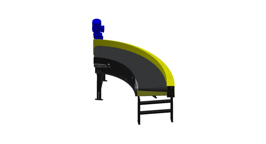
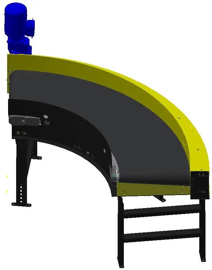
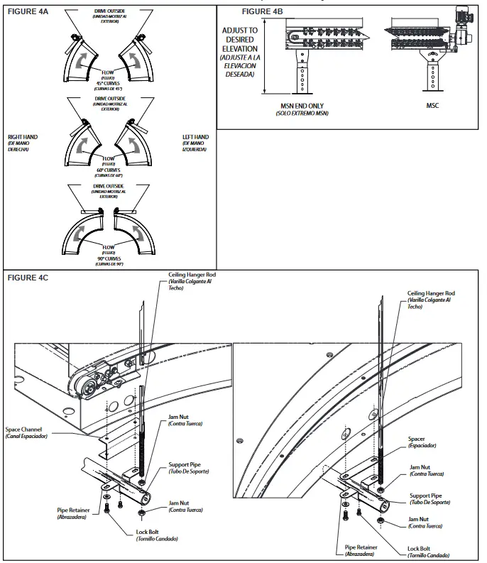
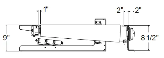
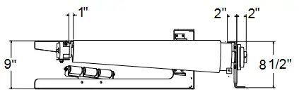
- Determine direction of product flow. The drive is located at the discharge end of the Model SBC. See Figure 4A.
- Position conveyor in sequence per match-mark numbers at each end.
- Attach supports as show in Figure 4B. Adjust elevation to required height.
NOTE: If celing hangers are used, see Ceiling Hangers section. - Install electrical controls and wire motor.
Ceiling Hanger Installation
If conveyors are to be used in an overhead application, ceiling hangers may have been supplied in place of floor supports. Figure 4C shows how a ceiling hanger mounts to a conveyor section. Ceiling hangers should be mounted at section joints. Ceiling Hanger Rod needs to be a minimum of 3″ from the inside channel. For safety information concerning conveyors mounted overhead, refer to “Installation Safety Precautions” on Page 3.
• Electrical Equipment
WARNING! Electrical controls shall be installed and wired by a qualified electrician. Wiring information for the motor and controls are furnished by the equipment manufacturer.
CONTROLS
Electrical Code: All motor controls and wiring shall conform to the National Electrical Code (Article 670 or other applicable articles) as published by the National Fire
Protection Association and as approved by the American Standards Institute, Inc.
CONTROL STATIONS
A) Control stations should be so arranged and located that the operation of the equipment is visible from them, and shall be clearly marked or labeled to indicate the function controlled.
B) A conveyor which would cause injury when started shall not be started until employees in the area are alerted by a signal or by a designated person that the conveyor is about to start.
When a conveyor would cause injury when started and is automatically controlled or must be controlled from a remote location, an audible device shall be provided which can be clearly heard at all points along the conveyor where personnel may be present. The warning device shall be actuated by the controller device starting the conveyor and shall continue for a required period of time before the conveyor starts. A flashing light or similar visual warning may be used in conjunction with or in place of the audible device if more effective in particular circumstances.
Where system function would be seriously hindered or adversely affected by the required time delay or where the intent of the warning may be misinterpreted (i.e., a work area with many different conveyors and allied devices), clear, concise, and legible warning shall be provided. The warning shall indicate that conveyors and allied equipment may be started at any time, that danger exists, and that personnel must keep clear. The warnings shall be provided along the conveyor at areas not guarded by position or location.
C) Remotely and automatically controlled conveyors, and conveyors where operator stations are not manned or are beyond voice and visual contact from drive areas, loading areas, transfer points, and other potentially hazardous locations on the conveyor path not guarded by location, position, or guards, shall be furnished with emergency stop buttons, pull cords, limit switches, or similar emergency stop devices.
All such emergency stop devices shall be easily identifiable in the immediate vicinity of such locations unless guarded by location, position, or guards. Where the design, function, and operation of such conveyor clearly is not hazardous to personnel, an emergency stop device is not required.
The emergency stop device shall act directly on the control of the conveyor concerned and shall not depend on the stopping of any other equipment. The emergency stop devices shall be installed so that they cannot be overridden from other locations.
D) Inactive and unused actuators, controllers, and wiring should be removed from control stations and panel boards, together with obsolete diagrams, indicators, control labels, and other material which serve to confuse the operator.
SAFETY DEVICES
A) All safety devices, including wiring of electrical safety devices, shall be arranged to operate in a “Fail-Safe” manner, that is, if power failure or failure of the device itself would occur, a hazardous condition must not result.
B) Emergency Stops and Restarts. Conveyor controls shall be so arranged that, in case of emergency stop, manual reset or start at the location where the emergency stop was initiated, shall be required of the conveyor(s) and associated equipment to resume operation.
C) Before restarting a conveyor which has been stopped because of an emergency, an inspection of the conveyor shall be made and the cause of the stoppage determined. The starting device shall be locked out before any attempt is made to remove the cause of stoppage, unless operation is necessary to determine the cause or to safely remove the stoppage.
Refer to ANSI Z244.1-1982, American National Standard for Personnel Protection
– Lockout/Tagout of Energy Sources – Minimum Safety Requirements and OSHA Standard Number 29 CFR 1910.147 “The Control of Hazardous Energy (Lockout/ Tagout).”
OPERATION
- Only trained employees shall be permitted to operate conveyors. Training shall include instruction in operation under normal conditions and emergency situations.
- Where employee safety is dependent upon stopping and/or starting devices, they shall be kept free of obstructions to permit ready access.
- The area around loading and unloading points shall be kept clear of obstructions which could endanger personnel.
- No person shall ride the load-carrying element of a conveyor under any circumstances unless that person is specifically authorized by the owner or employer to do so. Under those circumstances, such employee shall only ride a conveyor which incorporates within its supporting structure, platforms or control stations specifically designed for carrying personnel. Under no circumstances shall any person ride on any element of a vertical conveyor. Owners of conveyors should affix warning devices to the conveyor reading. Do Not Ride Conveyor.
- Personnel working on or near a conveyor shall be instructed as to the location and operation of pertinent stopping devices.
- A conveyor shall be used to transport only material it is capable of handing safety.
- Under no circumstances shall the safety characteristics of the conveyor be altered if such alterations would endanger personnel.
- Routine inspections and preventive and corrective maintenance programs shall be conducted to insure that all safety features and devices are retained and function properly.
- Personnel should be alerted to the potential hazard of entanglement in conveyors caused by items such as long hair, loose clothing, and jewelry.
- As a general rule, conveyors should not be cleaned while in operation. Where properly cleaning requires the conveyor to be in motion and a hazard exists, personnel should be made aware of the associated hazard.
• Conveyor Start-Up
Before conveyor is turned on, check for foreign objects that may have been left inside the conveyor during installation. These objects could cause serious damage during start-up.
After conveyor has been turned on and is operating, check motors, reducers, and moving parts to make sure they are working freely.
MAINTENANCE
- Maintenance, such as lubrication and adjustments, shall be performed only by qualified and trained personnel.
- It is important that a maintenance program be established to insure that all conveyor components are maintained in a condition which does not constitute a hazard to personnel.
- When a conveyor is stopped for maintenance purposes, starting devices or powered, accessories shall be locked or tagged out in accordance with a formalized procedure designed to protect all person or groups involved with the conveyor against an unexpected start.
- Replace all safety devices and guards before starting equipment for normal operation.
- Whenever practical, DO NOT lubricate conveyors while they are in motion. Only trained personnel who are aware of the hazard of the conveyor in motion shall be allowed to lubricate.
• Lubrication
BEARINGS
STANDARD: Supplied sealed and pre-lubricated. No lubrication required.
REDUCERS
MANUFACTURED BY HYTROL: See separate manual in Packing Envelope that contains lubrication and maintenance instructions for HYTROL’s Gear Reducer.
MANUFACTURED BY OTHERS: Refer to their recommendations.
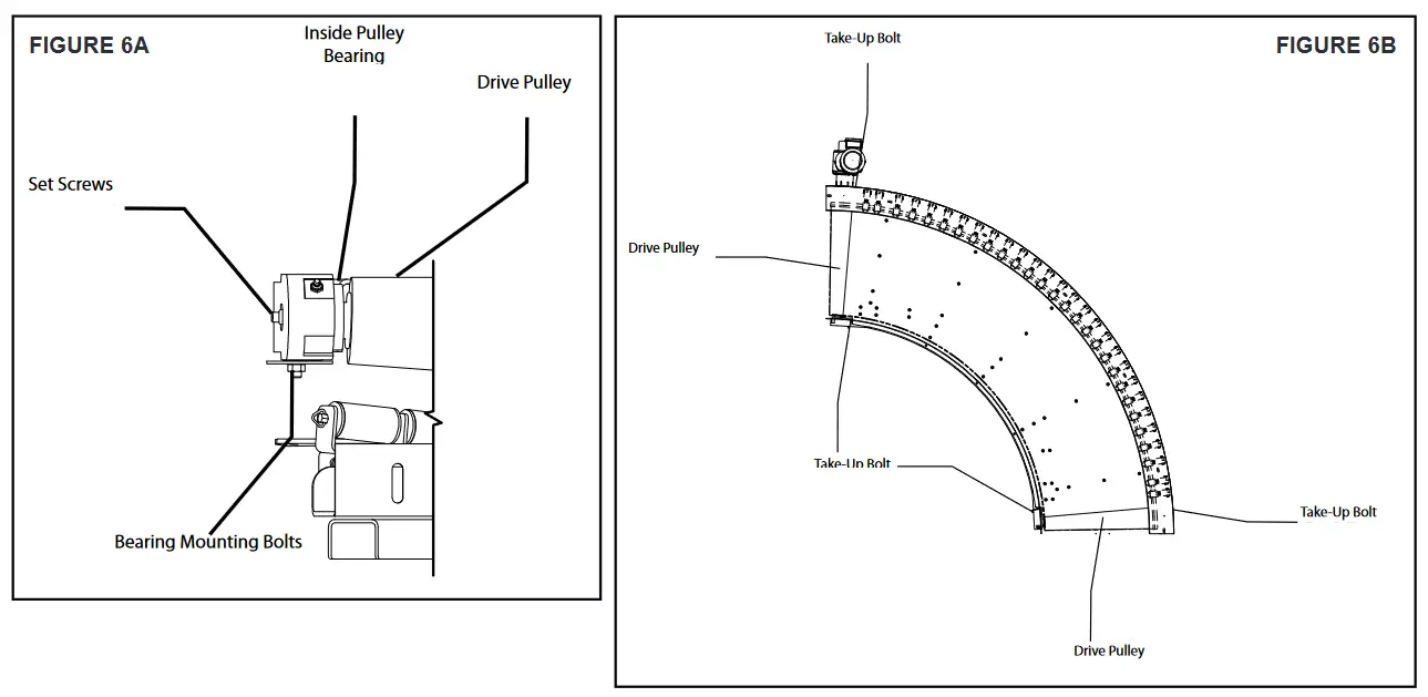
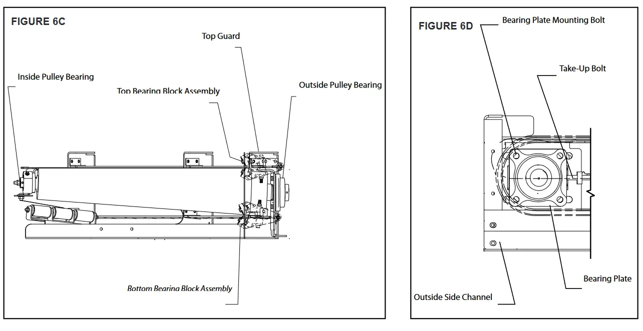
• Belt Removal
The model SBC is designed to allow for easy belt replacement. If it should become necessary to remove and/or replace a belt, the following procedure should be used (Figures 6A, 6B, 6C, and 6D).
BELT REMOVAL
- Perform Lockout Tagout procedures.
- Remove Belt Guide Guard.
- Remove outer Lexan cover.
- Loosen outer infeed pulley flange bearing bolts.
- Loosen outside take up/Jack Bolts.
- Loosen all (top and bottom) belt guide clamps on outside enough to take belt out over bead profile.
- Remove pulley nip point guards.
- Loosen and slide down lateral and vertical belt nip point guards.
- Remove inside flange bearing shield on infeed end.
- Remove inside channel covers.
- Loosen return belt carrier roller bracket bolts and lower elevation of carrier rollers.
- Loosen infeed jack bolt on inside bolts securing flange bearing support plate.
- Slide infeed inside pulley inwards.
- Remove belt.
• Belt Install
- On inside, slide on belt ensuring passage and clearance of belt bottom above carrier rollers.
- On outside ensure belt bead is in nominal position underneath belt guide bearing along full length along the top and bottom. Also, make sure the bead is not riding on top of either pulley.
- Starting on drive end, secure bottom and top belt guide clamps sequentially toward infeed end using dry torque of 20 ft-lb.
- Move outer flange bearing to nominal position; snug up jack bolt and torque nuts on carriage bolts (outer infeed end).
- Move inner flange bearing to nominal position, snug up jack bolt. Ensure flange bearing support bracket is level with bed and tighten flange bearing bracket bolts.
- Adjust belt carrier rollers where slight contact is maintained between roller and belt.
- Install inside channel and guard rails.
- Replace flange bearing shield on inside infeed end.
- Replace Lexan cover.
- Replace outer guard.
- Replace all nip point guards allowing 3/16″ clearance to belt outer surface.
- Test Run Belt.
• Troubleshooting
The following chart list possible problems that may occur in the operation of a powered conveyor.
TROUBLESHOOTING DRIVES
| TROUBLE | CAUSE | SOLUTION |
| Conveyor will not start or motor quits frequently. | 1) Motor is overloaded or is drawing too much current. | 1)Check for overloading of conveyor. 2)Check heater or circuit breaker and change if necessary. |
| Loud popping or grinding noise. | 1)Defective bearing. 2)Loose set screws in bearing. | 1)Replace bearing. 2)Tighten set screw. |
| Motor or reducer overheating. | 1)Conveyor is overloaded. 2)Low voltage to motor. 3)Low lubricant level in reducer. | 1)Check capacity of conveyor and reduce load to recommended level. 2)Have electrician check and correct as necessary. 3)Relubricate per manufacturer’s recommendations. |
| Damage to belt. | 1)Belt too tight. 2)Overload condition. 3)Belt Guard cutting belt. 4)Defective roller bearing on belt guide assembly. | 1)Loosen inside and outside take-up. 2)Check for overloading of conveyor. 3)Adjust belt guard to allow 1/8″ clearance. 4)Replace belt guide assembly. |
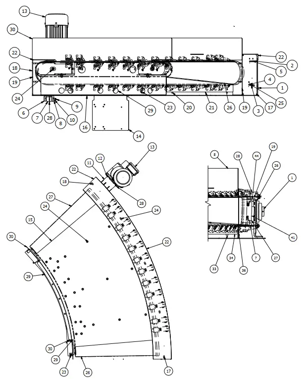
Model SBC 90° Parts Drawing
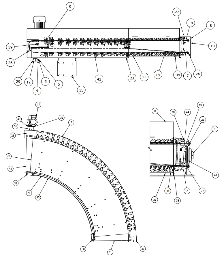
• Model SBC 90° Parts List
| Ref. # | DESCRIPTION |
| 1 | Bearing – Cast Iron, 4-Bolt |
| 2 | A/C Varied Speed |
| 3 | 3/8-16 X 3″ Hex Bolt |
| 4 | 3/8-16 X 3″ Hex head Cap Screw |
| 5 | 3/8-16 NC2B Hex Locknut- Nylon Insert |
| 6 | 3/8″ Flat Steel Washer |
| 7 | Belt Guide Bottom Plate – LH |
| 8 | Belt Guide Guide Weld |
| 9 | Type A Inside Groove Weld |
| 10 | Outside Lexan Curve – LH |
| 11 | Nord Gearmotor |
| 12 | Urethane Bushing |
| 13 | Motor Disconnect Switch |
| 14 | Hypower |
| 15 | Hypower Male 2M Pigtail |
| 16 | Support Assembly |
| 17 | Center Support Leg |
| 18 | Bed Brace – LH |
| 19 | Belt Guide Top Plate |
| 20 | Lower Outside Cover Plate |
| 21 | Upper Outside Cover Plate |
| 22 | Slider Plate |
| 23 | Bottom Plate |
| 24 | Bed Brace End – LH |
| 25 | Bed Brace End – RH |
| 26 | Bearing Spacer – 4-Bolt |
| 27 | Attachment Angle |
| 28 | Angle |
| 29 | Torque Arm Channel |
| 30 | Bearing Channel Drive |
| 31 | Shaft Guard Half |
| 32 | Shaft Guard Half |
| 33 | End Guard Angle |
| 34 | End Guard Plate |
| 35 | VSC Drive Powerflex 520 Bracket |
| 36 | End Guard Side Plate |
| 37 | Belt Guide Bridge Clamp Kit – Type A ( |
| 38 | Inside Take-Up Assembly – LH |
| 39 | Inside Take-Up Assembly – RH |
| 40 | Belt Return Idler Assembly – LH (Not Shown) |
| 41 | Tail Pulley |
| 42 | Drive Pulley |
| 43 | Inside Channel Weld |
| 44 | Bearing Pedestal Weld – LH |
| 45 | Torque Arm Weld |
• Model SBC 60° Parts Drawing
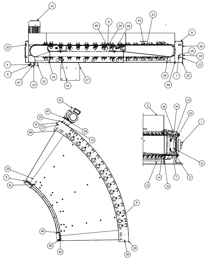
• Model SBC 60° Parts List
| Ref. # | DESCRIPTION |
| 1 | Bearing – Cast Iron, 4-Bolt |
| 2 | AC VAR SPD |
| 3 | Hex Bolt – Full Thread |
| 4 | Hex Head Cap Screw |
| 5 | Hex Locknut- Nylon Insert |
| 6 | Flat Steel Washer |
| 7 | Belt Guide Bottom Plate – LH |
| 8 | Belt Guide Guide Weld |
| 9 | Type A Inside Gear Weld |
| 10 | Outside Lexan Curve – LH |
| 11 | Spacer |
| 12 | Nord Gearmotor |
| 13 | Urethane Bushing – Cylinder Mounting ProSort 400E |
| 14 | Belt/Profile Assembly |
| 15 | Motor Disconnect Switch |
| 16 | Hypower |
| 17 | Hypower Male 2M Pigtail |
| 18 | Support Assembly |
| 19 | Center Support Leg |
| 20 | Bed Brace – LH |
| 21 | Belt Guide Top Plate |
| 22 | Lower Outside Cover Plate |
| 23 | Upper Outside Cover Plate |
| 24 | Slider Plate |
| 25 | Bottom Plate |
| 26 | Bed Brace End – LH |
| 27 | Bed Brace End – RH |
| 28 | Bearing Spacer – 4-BOLT |
| 29 | Attachment Angle |
| 30 | Angle |
| 31 | Torque Arm Channel |
| 32 | Bearing Channel Drive |
| 33 | Shaft Guard Half |
| 34 | Shaft Guard Half |
| 35 | End Guard Angle |
| 36 | End Guard Plate |
| 37 | VSC Drive Powerflex 520 Bracket |
| 38 | End Guard Side Plate |
| 39 | Belt Guide Bridge Clamp Kit – Type A |
| 40 | Inside Take-Up Assembly – LH |
| 41 | Inside Take-Up Assembly – RH |
| 42 | Belt Return Idler Assembly – LH |
| 43 | Tail Pulley |
| 44 | Drive Pulley |
| 45 | Inside Channel Weld |
| 46 | Bearing Pedestal Weld -LH, Belt Curve |
| 47 | Torque Arm Weld – Gearmotor NMRVP063 |
• Model SBC 45° Parts Drawing
• Model SBC 45° Parts List
| Ref. # | DESCRIPTION |
| 1 | Bearing – Cast Iron, 4-Bolt |
| 2 | AC VAR SPD |
| 3 | Hex Bolt – Full Thread |
| 4 | Hex Head Cap Screw, ZP |
| 5 | Hex Locknut – Nylon Insert |
| 6 | Flat Steel Washer |
| 7 | Belt Guide Bottom Plate – LH |
| 8 | Belt Guide Guide Plate |
| 9 | Type A Inside Gear Weld |
| 10 | Outside Lexan Curve – LH |
| 11 | Spacer |
| 12 | Nord Gearmotor |
| 13 | Urethane Bushing – Cylinder Mounting ProSort 400E |
| 15 | Motor Disconnect Switch |
| 16 | Hypower |
| 17 | Hypower Male 2M Pigtail |
| 18 | Support Assembly |
| 19 | Center Support Leg |
| 20 | Bed Brace – LH |
| 21 | Belt Guide Top Plate |
| 22 | Lower Outside Cover Plate |
| 23 | Upper Outside Cover Plate |
| 24 | Slider Plate |
| 25 | Bottom Plate |
| 26 | Bed Brace End – LH |
| 27 | Bed Brace End – RH |
| 28 | Bearing Spacer – 4-Bolt |
| 29 | Attachment Angle |
| 30 | Angle |
| 31 | Torque Arm Channel |
| 32 | Bearing Channel Drive |
| 33 | Shaft Guard Half – 2-5/8″ |
| 34 | Shaft Guard Half – 3″ |
| 35 | End Guard Angle |
| 36 | End Guard Plate |
| 37 | VSC Drive Powerflex 520 Bracket |
| 38 | End Guard Side Plate |
| 39 | Belt Guide Bridge Clamp Kit – Type A |
| 40 | Inside Take-Up Assembly – LH |
| 41 | Inside Take-Up Assembly – RH |
| 42 | Belt Return Idler Assembly – LH |
| 43 | Tail Pulley |
| 44 | Drive Pulley |
| 45 | Inside Channel Weld |
| 46 | Bearing Pedestal Weld – LH, Belt Curve |
| 47 | Torque Arm Weld – Gearmotor NMRVP063 |
• Preventive Maintenance Checklist
Note: Check Set Screw for proper torque value after the first 24 hours of operation.
The following is a general maintenance checklist which covers the major components of your conveyor. This will be helpful in establishing a standard maintenance schedule.
| COMPONENT | SUGGESTED ACTION | SCHEDULE | ||
| W | M | Q | ||
| Motor | Check Noise | |||
| Check Temperature | ||||
| Check Mounting Bolts | ||||
| Reducer | Check Noise | |||
| Check Temperature | ||||
| Check Oil Level | ||||
| Belt | Check Tension | |||
| Check Wear and Tear | ||||
| Check Bearings on Belt Guides Making Contact | ||||
| Bearings | Check Noise | |||
| Check Mounting Bolts | ||||
| Structural | General Check: Check All Loose Bolts, etc. tightened | |||
W = WEEKLY (Semanal) M = MONTHLY (Mensual) Q = QUARTERLY (Trimestral)

HYTROLPARTS.COM
“Building Relationships One Conveyor
Part at a Time” [email protected] |www.HytrolParts.com
Use code HYPMANUAL for free shipping
on your first order at HytrolParts.com
[email protected] | www.HytrolParts.com


