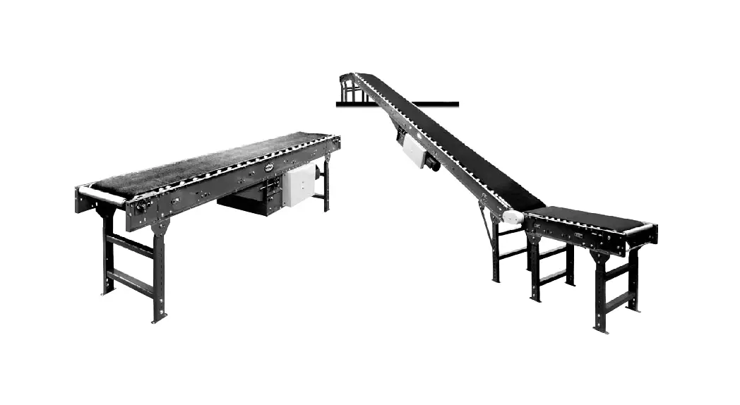
![]() RB Roller Bed Belt Conveyor
RB Roller Bed Belt Conveyor
Instruction Manual
Installation and Maintenance
Manual with Safety Information and Parts List
RECOMMENDED SPARE PARTS HIGHLIGHTED IN GRAY
Effective April 2011
(Supersedes April 2009)
Model RB & RBI
Bulletin #633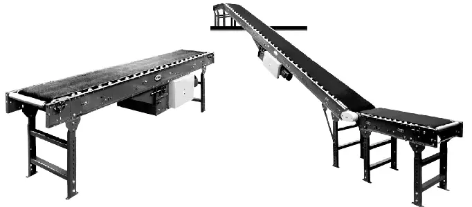
IMPORTANT! DO NOT DESTROY
INTRODUCTION
This manual provides guidelines and procedures for installing, operating, and maintaining your conveyor. A complete parts list is provided with recommended spare parts highlighted in gray. Important safety information is also provided throughout the manual. for safety to personnel and for proper operation of your conveyor, it is recommended that you read and follow the instructions provided in this manual.
Receiving and Ingratiating
- Check the number of items received against the bill of lading.
- Examine condition of equipment to determine if any damage occurred during shipment.
- Move all crates to area of installation.
- Remove crating and check for optional equipment that may be fas- tened to the conveyor. make sure these parts (or any foreign pieces) are removed.
NOTE: If damage has occurred or freight is missing, Contact your Trolley distributor.
How to Order Replacement Parts
Included in this manual are parts drawings with complete replacement parts lists. minor fasteners, such as nuts and bolts, are not included. When ordering replacement parts:
- Contact dealer from whom conveyor was purchased or nearest TROLLEY distributor.
- Give Conveyor model Number and Serial Number or TROLLEY factory Order Number.
- Give Part Number and complete description from Parts List.
- Give type of drive. Example—8” End drive, 8” Center drive, etc.
- If you are in a breakdown situation, tell us.
INSTALLATION
Installation Safety
GUARDS AND GUARDING
Interfacing of Equipment. When two or more pieces of equipment are interfaced, special attention shall be given to the interfaced area to insure the presence of adequate guarding and safety devices.
Guarding Exceptions. Wherever conditions prevail that would require guarding under these standards, but such guarding would render the conveyor unusable, prominent warning means shall be provided in the area or on the equipment in lieu of guarding.
Guarded by Location or Position. Where necessary for the protection of employees from hazards, all exposed moving machinery parts that present a hazard to employees at their work station shall be mechanically or electrically guarded, or guarded by location or position.
When a conveyor passes over a walkway, roadway, or work station, it is considered guarded solely by location or position if all moving parts are at least 8 ft. (2.44 m) above the floor or walking surface or are otherwise located so that the employee cannot inadvertently come in contact with hazardous moving parts.
Although overhead conveyors may be guarded by location, spill guard, pan guards, or equivalent shall be provided if the product may fall off the conveyor for any reason and if personnel would be endangered.
HEADROOM
When conveyors are installed above exit passageways, aisles, or corridors, there shall be provided a minimum clearance of 6 ft. 8 in. (2.032 m) measured vertically from the floor or walking surface to the lowest part of the conveyor or guards.
Where system function will be impaired by providing the minimum clearance of 6 ft. 8 in. (2.032 m) through an emergency exit, alternate passageways shall be provided.
It is permissible to allow passage under conveyors with less than 6 ft. 8 in. (2.032 m) clearance from the floor for other than emergency exits if a suitable warning indicates low headroom.
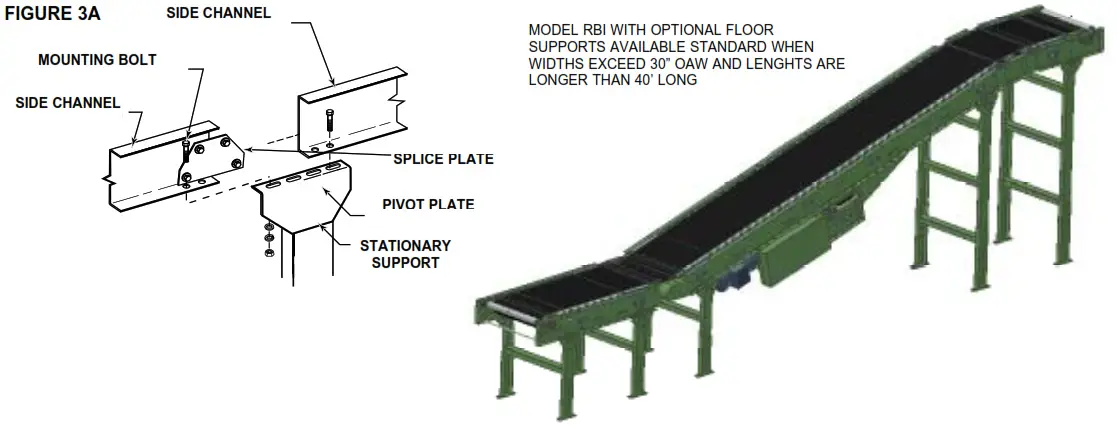
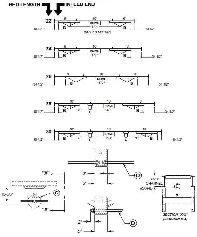
Support Installation
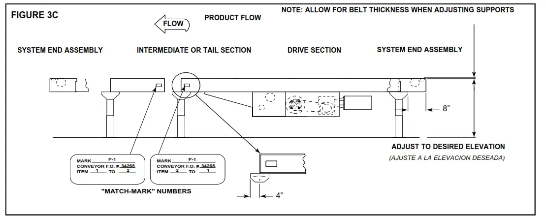
- determine primary direction of product flow. figure 3C indicates the preferred flow as related to the drive.
- Refer to “match-mark” numbers on ends of conveyor sections. (figure 3C) Position them in this sequence near the area of installation.
- Attach supports to both ends of drive section and to one end of intermediate or tail sections (figure 3C). Hand tighten bolts only at this time. On RBI conveyors the angle of incline will determine where the knee brace mounting brackets are to be placed when required.
- Adjust elevation to required height.
Ceiling Hanger Installation
If conveyors are to be used in an overhead application, ceiling hangers may have been supplied in place of floor supports.
figure 3B shows how a ceiling hanger mounts to a conveyor section. Ceiling hangers should be mounted at section joints. for safety information concerning conveyors mounted overhead, refer to “Installation Safety Precautions” above.
Conveyor Set-Up
mark a chalk line on floor to locate center of the conveyor (floor mounted Conveyors).
Place the drive section in position.
Install remaining sections placing end without support on extend support of previous section (figure 3C). Check “match mark” Numbers to see that adjoining sections are in proper sequence fasten sections together with splice plates and pivot plates (figure 3C). Hand tighten bolts only.
Check to see that conveyor is level across width and length of unit. Adjust supports and ceiling hangers as necessary. Install electrical controls and wire motor. See Pages 4 and 5. Install and track belt per instructions on Pages 4, 5, and 6.
Support Installation
Ceiling Hanger Installation
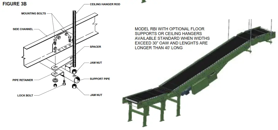
NOTE: When installing ceiling hanger rods in an existing building, all methods of attachment must comply with local building codes.
Conveyor Set-Up
Belt Installation
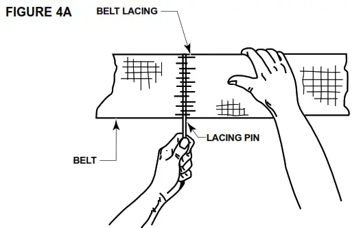
The conveyor belt has been cut to the proper length and lacing installed at the factory. To install follow these steps:
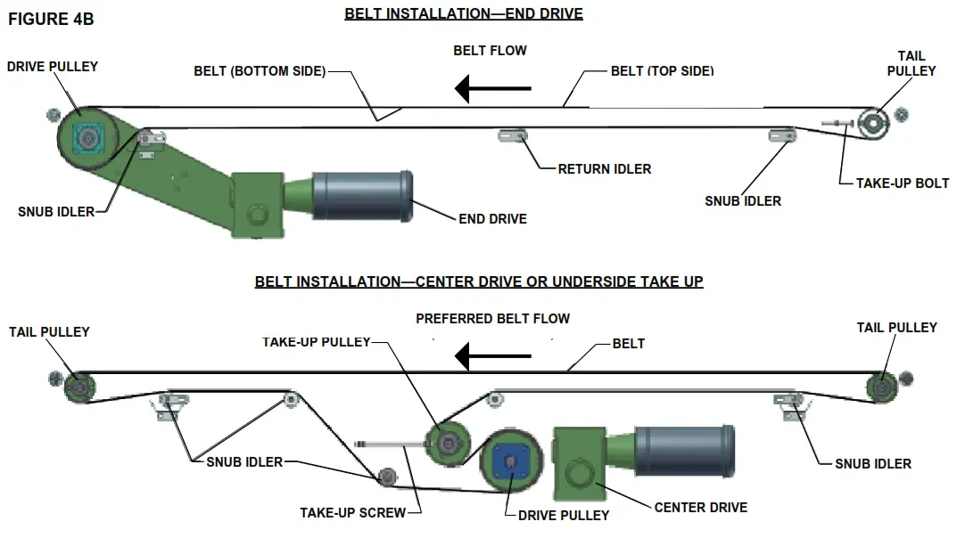
- Thread belt through conveyor as shown (figure 4B).
- Pull ends together and insert lacing pin (figure 4A).
- Adjust belt tension with take-up pulley or tail pulley. Keep pulley square by moving both take-up bolts an equal amount. maintain enough tension so drive pulley will not slip when carrying the rated load.
- Track belt per instructions on Pages 5-6.
NOTE: If belt ends cannot be pulled together by hand, it may be necessary to loosen take-ups (at tail pulley, etc.), minimum position or use a belt puller so lacing pin can
be easily inserted.
| BELT WIDTH | LACING ANGLE |
| 4″-20″ | 2 1/2° |
| 22″-60″ | 2 1/2° |
CAUTION!
Excessive slippage will reduce belt life and damage drive pulley lagging. Never apply more tension than is needed. Over-tension will cause extra wear to belt and bearings and will require extra power from drive.
Racked Sections
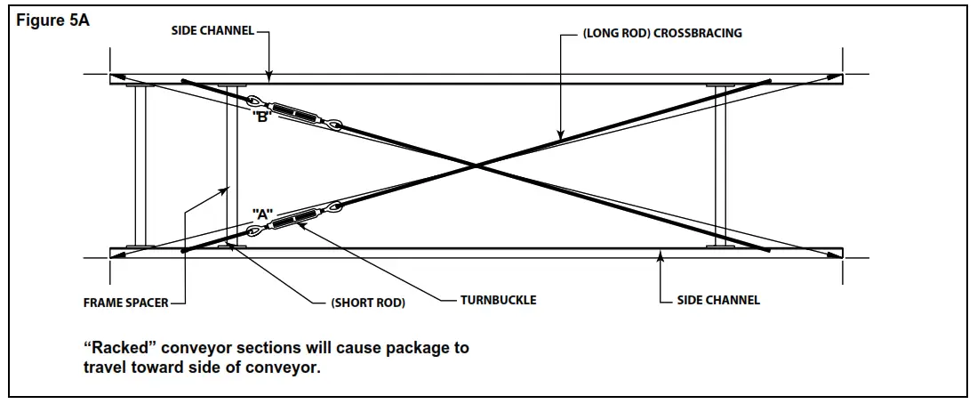
It is important that each bed section be checked for a “racked” or out-of square condition. If conveyor is not square, tracking problems will result. TO CORRECT AN OUT- Of SQUARE SECTION
- Locate points on corners of section and measure distance “A” & “B”. If the dimensions are not equal, the section will need to be squared. (figure 5A).
- Use cross bracing supplied on underside of conveyor to square each section. Adjust turnbuckle until dimensions “A” & “B” are equal.
- After all bed sections have been checked and corrected for “racked condition”, tighten all butt couplings and pivot plate bolts.
- make final check to see that all conveyor sections are level across width and length. If entire conveyor is level, supports can be lagged to floor.
IMPORTANT!
Being out of level across width of conveyor can cause package drift on long conveyor lines.
Electrical Equipment
WARNING!
Electrical controls shall be installed and wired by a qualified electrician.
Wiring information for the motor and controls are furnished by the equipment manufacturer.
CONTROLS
Electrical Code: All motor controls and wiring shall conform to the National
Electrical Code (Article 670 or other applicable articles) as published by the National fire Protection Association and as approved by the American Standards Institute, Inc.
CONTROL STATIONS
A) Control stations should be so arranged and located that the operation of the equipment is visible from them, and shall be clearly marked or labeled to indicate the function controlled.
B) A conveyor which would cause injury when started shall not be started until employees in the area are alerted by a signal or by a designated person that the conveyor is about to start.
When a conveyor would cause injury when started and is automatically
controlled or must be controlled from a remote location, an audible device shall be provided which can be clearly heard at all points along the conveyor where personnel may be present. The warning device shall be actuated by the controller device starting the conveyor and shall continue for a required period of time before the conveyor starts. A flashing light or similar visual warning may be used in conjunction with or in place of the audible device if more effective in particular circumstances. Where system function would be seriously hindered or adversely affected by the required time delay or where the intent of the warning may be misinterpreted (i.e., a work area with many different conveyors and allied devices), clear, concise, and legible warning shall be provided. The warning shall indicate that conveyors and allied equipment may be started at any time, that danger exists, and that personnel must keep clear. The warnings shall be provided along the conveyor at areas not guarded by position or location.
C) Remotely and automatically controlled conveyors, and conveyors where operator stations are not manned or are beyond voice and visual contact from drive areas, loading areas, transfer points, and other potentially hazardous locations on the conveyor path not guarded by location, position, or guards, shall be furnished with emergency stop buttons, pull cords, limit switches, or similar emergency stop devices. All such emergency stop devices shall be easily identifiable in the immediate vicinity of such locations unless guarded by location, position, or guards. Where the design, function, and operation of such conveyor clearly is not hazardous to personnel, an emergency stop device is not required. The emergency stop device shall act directly on the control of the conveyor concerned and shall not depend on the stopping of any other equipment. The emergency stop devices shall be installed so that they cannot be overridden from other locations.
D) Inactive and unused actuators, controllers, and wiring should be removed from control stations and panel boards, together with obsolete diagrams, indicators, control labels, and other material which serve to confuse the operator.
SAFETY DEVICES
A) All safety devices, including wiring of electrical safety devices, shall be arranged to operate in a “fail-Safe” manner, that is, if power failure or failure of the device itself would occur, a hazardous condition must not result.
B) Emergency Stops and Restarts. Conveyor controls shall be so arranged that, in case of emergency stop, manual reset or start at the location where the emergency stop was initiated, shall be required of the conveyor(s) and associated equipment to resume operation.
C) Before restarting a conveyor which has been stopped because of an emergency, an inspection of the conveyor shall be made and the cause of the stoppage determined. The starting device shall be locked out before any attempt is made to remove the cause of stoppage, unless operation is necessary to determine the cause or to safely remove the stoppage. Refer to ANSI z244.1-1982, American National Standard for Personnel Protection – Lockout/Tagout of Energy Sources – minimum Safety Requirements and OSHA Standard Number 29 Cf R 1910.147 “The Control of Hazardous Energy (Lockout/Tagout).”
OPERATION
Operation Safety Precautions
A) Only trained employees shall be permitted to operate conveyors. Training shall include instruction in operation under normal conditions and emergency situations.
B) Where employee safety is dependent upon stopping and/or starting devices, they shall be kept free of obstructions to permit ready access.
C) The area around loading and unloading points shall be kept clear of obstructions which could endanger personnel.
D) No person shall ride the load-carrying element of a conveyor under any circumstances unless that person is specifically authorized by the owner or employer to do so. Under those circumstances, such employee shall only ride a conveyor which incorporates within its supporting structure, platforms or control stations specifically designed for carrying personnel. Under no circumstances shall any person ride on any element of a vertical conveyor.
Owners of conveyors should affix warning devices to the conveyor reading
do Not Ride Conveyor.
E) Personnel working on or near a conveyor shall be instructed as to the location and operation of pertinent stopping devices.
F) A conveyor shall be used to transport only material it is capable of handling safely.
G) Under no circumstances shall the safety characteristics of the conveyor be altered if such alterations would endanger personnel.
H) Routine inspections and preventive and corrective maintenance programs shall be conducted to insure that all safety features and devices are retained and function properly.
I) Personnel should be alerted to the potential hazard of entanglement in conveyors caused by items such as long hair, loose clothing, and jewelry.
J) As a general rule, conveyors should not be cleaned while in operation.
Where proper cleaning requires the conveyor to be in motion and a hazard exists, personnel should be made aware of the associated hazard.
Belt Tracking
HOW IS THE CONVEYOR BELT TRACKED
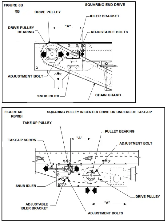
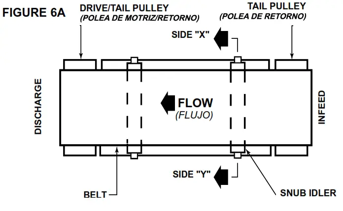
The belt is tracking by adjusting: drive Pulley, Tail Pulley, Return Idlers, and Snub Idlers. The same tracking principles apply to conveyors supplied with end drives, center drives, or underside take-ups.
PER-TRACKING INSPECTION
Before attempting to physically track the belt:
- make sure conveyor is level across the width and length of unit. Adjust supports as necessary.
- Check to make sure: drive Pulley, Tail Pulley, Snub Idlers, and all Return Idlers are square with conveyor bed. See illustrations 6B, 6C, 6E, and 6d. dimension “A” should be equal on both sides of unit.
- make sure belt has been properly threaded through conveyor. See page 4.
- make sure belt lacing has been installed correctly and is square with the belt. See page 4.
- Check for improper loading. feed should be in direction of belt travel, centered on belt.
IMPORTANT: When belt tracking adjustments are made, they should be minor (1/16 in. at a time on idlers, etc., should be sufficient.). Give the belt adequate time to react to the adjustments. It may take several complete revolutions around the conveyor for the belt to begin tracking properly on long, slow conveyor lines.
A) Stand at tail pulley looking toward drive and note what direction belt is traveling. B) Having observed belt and determined tracking problem, follow procedures in “How to Steer The Belt”, See figure 6A. HOW TO STEER THE BELT
Condition 1. . .When the belt is running in the direction (f Low) with the arrow, but tracking (drifting) towards Side “X”, move the Snub Idler nearest the In Feed end of Side “Y” towards the dis Charge end of the conveyor.
Condition 2. . . When the belt is running in the direction (f Low) with the arrow, but tracking (drifting) towards Side “Y”, move the Snub Idler nearest the In Feed end of Side “X” towards the dis Charge end of the conveyor.
If Belt direction (f Low) is reversed, all the above conditions will remain the same as in figure 6A, except you are now viewing the conveyor from the opposite end. If belt continues to track improperly, re-check all items covered in “Sidetracking Inspection” and make corrections as necessary.
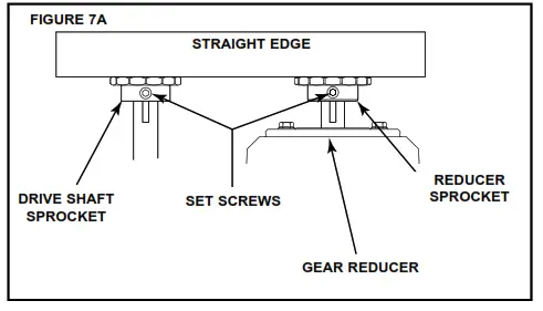
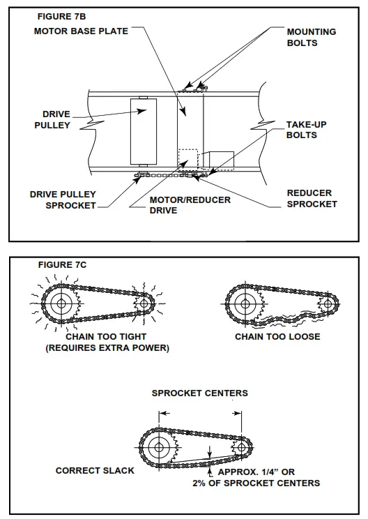
Drive Chain Alignment and Tension
The drive chain and sprockets should be checked periodically for proper tension and alignment. Improper adjustment will cause extensive wear to the drive components.
TO MAKE ADJUSTMENTS
- Remove chain guard.
- Check sprocket alignment by placing a straightedge across the face of
Belt Tracking NOTE: In all conditions, you are viewing the Conveyor Belt from the
INDEED end. All corrections will be made from the INDEED end of conveyor. CAUTION!
Only trained personnel should track conveyor belt which must be done while conveyor is in operation. both sprockets (figure 7A). Loosen set screws and adjust as needed. - Re-tighten set screws.
- To adjust chain tension, loosen bolts that fasten motor base to mounting angles, both sides of the conveyor. Tighten take-up bolts until desired chain tension is reached. (figures 7B & 7C). Re-tighten mounting bolts.
- Lubricate chain per lubrication instructions.(Page 7)
- Replace chain guard so that it does not interfere with drive.
 NOTE: In all conditions, you are viewing the Conveyor Belt from the
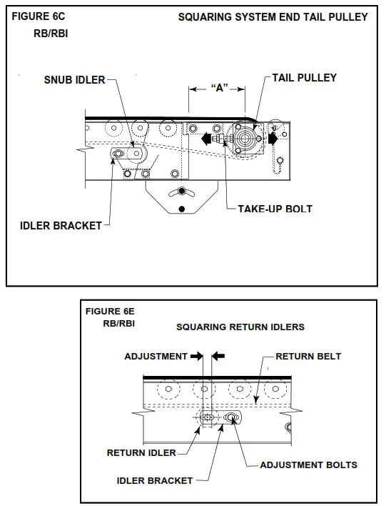 CAUTION!
Drive Chain Alignment and Tension
CAUTION!
Never remove chain guards while the conveyor is running. Always replace guards after adjustments are made.
MAINTENANCE
Conveyor Start-Up
Before conveyor is turned on, check for foreign objects that may have been left inside conveyor during installation. These objects could cause serious damage during start-up.
After conveyor has been turned on and is operating, check motors, reducers, and moving parts to make sure they are working freely.
CAUTION!
Because of the many moving parts on the conveyor, all personnel in the area of the conveyor need to be warned that the conveyor is about to be started.
Maintenance Safety Precautions
A) maintenance, such as lubrication and adjustments, shall be performed only by qualified and trained personnel.
B) It is Important that a maintenance program be established to insure that all conveyor components are maintained in a condition which does not constitute a hazard to personnel.
C) When a conveyor is stopped for maintenance purposes, starting devices or powered accessories shall be locked or tagged out in accordance with a formalized procedure designed to protect all person or groups involved with the conveyor against an unexpected start.
d) Replace all safety devices and guards before starting equipment for normal operation.
E) Whenever practical, do NOT lubricate conveyors while they are in motion.
Only trained personnel who are aware of the hazard of the conveyor in motion shall be allowed to lubricate.
SAFETY GUARDS
maintain all guards and safety devices IN POSITION and IN SAFE REPAIR.
WARNING SIGNS
maintain all warning signs in a legible condition and obey all warnings. See Safety manual for examples of warning signs.
Lubrication
The drive chain is per-lubricated from the manufacturer by a hot dipping process that ensures total lubrication of all components.
However, continued proper lubrication will greatly extend the useful life of every drive chain. drive Chain lubrication serves several purposes including:
- Protecting against wear of the pin-bushing joint
- Lubricating chain-sprocket contact surfaces
- Preventing rust or corrosion for normal operating environments, lubricate every 2080 hours of operation or every 6 months, whichever comes first. Lubricate with a good grade of petroleum or synthetic oil (i.e., Shell Rosella or Mobil 1). for best results, always use a brush to generously lubricate the chain. The proper viscosity of lubricant greatly affects its ability to flow into the internal areas of the chain.
Refer to the table below for the proper viscosity of lubricant for your application.
| Ambient Temperature degrees f | SAE | ISO |
| 20-40 | 20 | 46 or 68 |
| 40-100 | 30 | 100 |
| 100-120 | 40 | 150 |
The drive chain’s lubrication requirement is greatly affected by the operating conditions. for harsh conditions such as damp environments, dusty environments, excessive speeds, or elevated temperatures, it is best to lubricate more frequently. It may be best, under these conditions, to develop a custom lubrication schedule for your specific application. A custom lubrication schedule may be developed by inspecting the drive chain on regular time intervals for sufficient lubrication. Once the time interval is determined at which the chain is not sufficiently lubricated, lubricate it and schedule the future lubrication intervals accordingly.
Trouble Shooting
The following charts list possible problems that may occur in the operation of the conveyor.
TROUBLE SHOOTING DRIVES
| TROUBLE | CAUSE | SOLUTION |
| Conveyor will not start or motor quits frequently. | 1) Motor is overloaded. 2) Motor is drawing too much current. | 1) Check for overloading of conveyor. 2) Check heater or circuit breaker and change if necessary. |
| Drive chain and sprockets wear excessively. | 1) Lack of lubrication on chain causing chain stretch which creates improper chain to sprocket mesh. 2) Sprockets are out of alignment. 3) Loose chain. | 1) Replace chain and sprockets. Provide adequate lubrication. NOTE: If problem reoccurs, a chain take-up may be required. 2) Align sprockets. See “Drive Chain Alignment and Tension”. 3) Tighten chain. |
| Loud popping or grinding noise. | 1) Defective bearing. 2) Loose set screws in bearing. 3) Loose drive chain. | 1) Replace bearing. 2) Tighten set screw. 3) Tighten chain. |
| Motor or reducer over- heating. | 1) Conveyor is overloaded. 2) Low voltage to motor. 3) Low lubricant level in reducer. | 1) Check capacity of conveyor and reduce load to recommended level. 2) Have electrician check and correct as necessary. 3) Re lubricate per manufacturer’s recommendations. For TROLLEY reducer, refer to separate manual. |
| Belt does not move, but drive runs. | 1) Conveyor is overloaded. 2) Belt is too loose. 3) Lagging on drive pulley is worn. | 1) Reduce load. 2) Use belt take-up to tighten belt. 3) Replace drive pulley lagging and tighten belt. |
TROUBLE SHOOTING DRIVE BELT TRACKING
| TROUBLE | CAUSE | SOLUTION |
| Entire length of belt creeps off at one spot only. | 1) One or more idlers (usually near trouble spot) are out of line. 2) One conveyor section not level or square. 3) Material build-up on pulleys or idlers. | 1) Adjust idlers as necessary. See “Tracking the belt” in this manual for details. 2) Make necessary adjustments to supports. 3) Remove residue from pulleys or idlers. Install belt, cleaners, or scrap- pers if possible. |
| Belt creeps to one side at tail pulley. | 1) Tail pulley, return idler, or snub idler near tail pul- ley not properly aligned or square with bed. | 1) Adjust as necessary. See “Belt Tracking Pr-Tracking Inspection” in this manual for details. |
| Entire belt creeps to one side. | 1) Conveyor not straight. 2) Conveyor not level. 3) Material build-up on rollers, pulleys, or idlers. | 1) Re-align bed sections as necessary. 2) Correct as necessary. 3) Remove residue and install belt cleaners or scrapers if possible |
REPLACEMENT PARTS
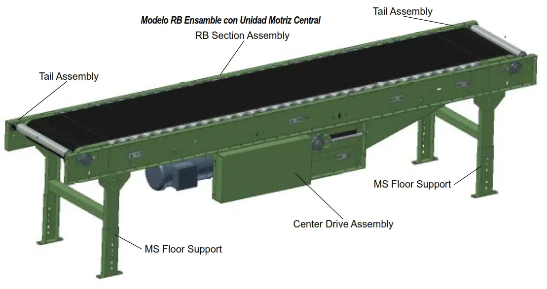
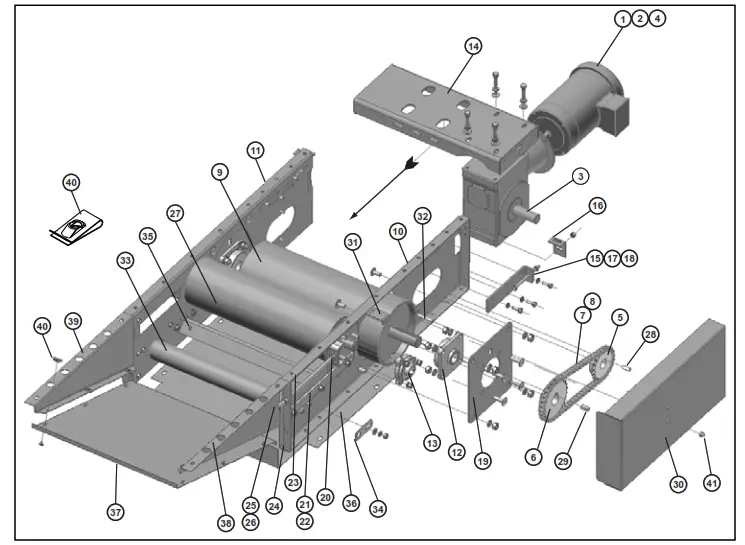
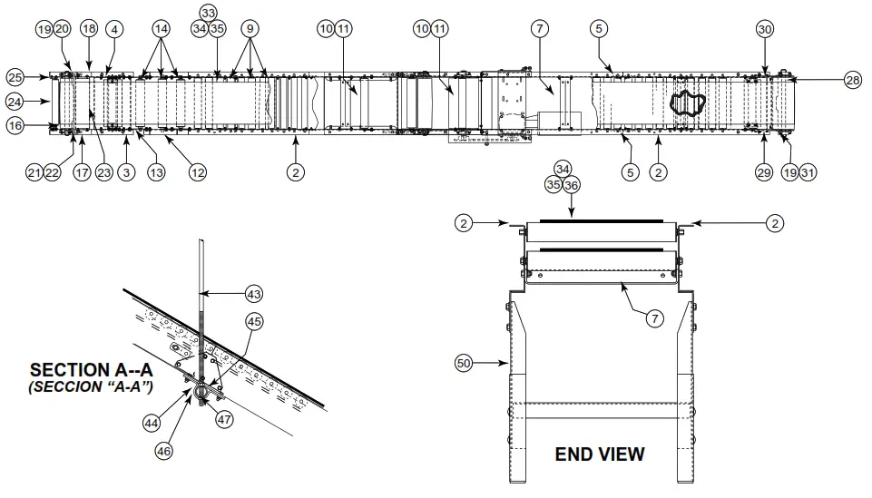
Model RB Assembly with Center Drive
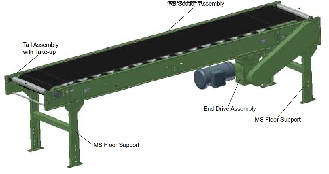
Model RB Assembly with End Drive
Model RB Parts Drawings and List (8” Center Drive)
| Ref. No. | Part No. | Description |
| 1 | — | Drive Assembly (See Page 11) |
| 2 | — | Frame Channel |
| — | B-04923 | 4’ Long |
| — | B-02636 | 5’ Long |
| — | B-05494 | 6’ Long |
| — | B-21606 | 7’ Long |
| — | B-12082 | 7’6” Long |
| — | B-09908 | 8’ Long |
| — | B-21607 | 9’ Long |
| — | B-02633 | 10’ Long |
| 3 | B-23316 | Splice Plate |
| 4 | B-03916 | Bed Spacer (Specify BR) |
| 5 | B-01982 | 1.9 in. Dia. Galvanized Roller (Specify BR) |
| 6 | B-03894 | 2-1/8 in. Dia. Snub Roller (Specify BR) |
| 7 | B-00944 | 7/16 in. Hex Idler Bracket |
| 8 | — | Tail Pulley |
| — | B-22323 | 4 in. Dia. 16 in. thru 28 in. OAW (Specify) |
| — | B-21755 | 6 in. Dia. 30 in. thru 54 in. OAW (Specify) |
| 9 | — | System End Channel—RH |
| — | B-20441 | 4 in. Pulley, 16 in. thru 28 in. OAW (Specify) |
| — | B-20443 | 6 in. Pulley, 30 in. thru 54 in. OAW (Specify) |
| 10 | — | System End Channel—LH |
| — | B-20442 | 4 in. Pulley, 16 in. thru 28 in. OAW (Specify) |
| — | B-20444 | 6 in. Pulley, 30 in. thru 54 in. OAW (Specify) |
| Ref. No. | Part No. | Description |
| 11 | — | 3-Bolt Flange Bearing |
| — | 010.102 | 4 in. Pulley—1 in. Bore |
| — | 010.103 | 6 in. Pulley—1-3/16 in. Bore |
| 12 | — | Bearing Spacer |
| — | B-14455 | 1 in. Bore |
| — | B-14456 | 1-3/16 in. Bore |
| 13 | 040.4041 | Take-up Bolt 1/2-13 x 2 inch Long |
| 14 | 041.201 | Hex Jam Nut, 1/2-13 |
| — | B-21162 | Slider Plate |
| — | B-21155 | 4 in. Pulley (Specify OAW) |
| — | 6 in. Pulley (Specify OAW) | |
| 16 | B-20445 | 1.9 in. Dia. Pop-Out Roller (Specify BR) |
| 17 | 090.262 | Pop-Out Roller Bracket |
| 18 | 091.110 | Cable Assembly |
| 19 | 090.107 | Small Hog Ring |
| 20 | — | Belt, Black Ultimate 140 BOS (Specify Width) |
| 21 | — | U1 Clipper Unibar Lacing |
| 22 | — | #13 Lacing Pin |
| 23 | B-12758 | Snub Roller Guard (Specify BR) |
| 24 | B-22350 | Snub Roller Guard Mounting Plate |
| 25 | 049.310 | U-Type Speed Nut, 1/4-20 |
| 26 | B-16659 | MS Type Support Assembly (Specify Elevation) |
8” Center Drive Assembly
| Ref. No. | Part No. | Description |
| 1 | — | Motor-C-Face |
| — | 030.7134 | 1/2 HP—230/460 VAC—3 Ph.—60 Hz.—TEFC |
| — | 030.7324 | 1 HP—230/460 VAC—3 Ph.—60 Hz.—TEFC |
| — | 030.7534 | 2 HP—230/460 VAC—3 Ph.—60 Hz.—TEFC |
| 2 | — | Brake Kit (Used only on Model RBI) |
| — | 031.27595 | 1/2 — 1 HP |
| — | 031.2795 | 1-1/2 — 2 HP |
| 3 | — | Speed Reducer** |
| — | R-00153-30R | 4AC—RH—30:1 Ratio |
| — | R-00164-30R | 5AC—RH—30:1 Ratio |
| 4 | — | Coupling Kit-Motor To Reducer |
| — | 052.145 | 1/2 — 1 HP |
| — | 052.146 | 1-1/2 — 2 HP |
| 5 | — | Sprocket-Reducer** |
| — | 028.133 | 50B14 x 1 in. Bore (4AC) |
| — | 028.1342 | 50B16 x 1-1/4 in. Bore (5AC) |
| 6 | — | Sprocket—Drive Pulley** |
| — | 028.13836 | 50B 28 x 1-7/16 in. Bore (4AC) |
| — | 028.111523 | 50B 32 x 1-7/16 in. Bore (5AC) |
| 7 | 029.101 | #50 Riveted Roller Chain |
| 8 | 029.201 | Connector Link—#50 Roller Chain |
| 9 | SA-040301 | 8 in. Dia. Ctr. Dr. Pulley (Fully Lagged) (Specify OAW) |
| 10 | PT-089429-R | RH Side Channel, Drive |
| 11 | PT-089429-L | LH Side Channel, Drive |
| 12 | 010.203015 | 4-Bolt Flange Bearing—1-7/16 in. Bore |
| 13 | 010.103 | 3-Bolt Flange Bearing—1-3/16 in. Bore |
| 14 | WA-026619 | Motor Base Amendment (Specify OAW) |
| Ref. No. | Part No. | Description |
| 15 | PT-089434 | Motor Base Take-up |
| 16 | PT-089438 | Motor Base Take-up Angle |
| 17 | 040.313 | Motor Base Take-Up Bolt—3/8-16 x 5 in. Long |
| 18 | 041.300 | Motor Base Hex Jam Nut—Heavy-3/8-16 |
| 19 | PT-090795 | Bearing Plate Center Drive |
| 20 | WA-027027 | Take-Up Plate Amendment |
| 21 | PT-089435 | Bearing Guide Spacer |
| 22 | PT-089436 | Bearing Guide |
| 23 | PT-089437 | Upper Bearing Guide |
| 24 | PT-090368 | Take-Up Angle |
| 25 | 044.116011 | Take-Up Bolt—1/2-13 x 11 in. Long |
| 26 | 041.201 | Hex Jam Nut—1/2-13 |
| 27 | WA-27034 | 6 in. Dia. Take-Up Pulley (Specify OAW) |
| 28 | 090.203 | Shaft Key—1/4 in. Sq. x 1 in. Long |
| 29 | 090.204 | Shaft Key—3/8 in. Sq. x 1 in. Long |
| 30 | PT-089430 | Chain Guard |
| 31 | PT-092699 | Guard Bracket |
| 32 | 040.3125 | Hex Head Cap Screw 3/8-16 x 4 1/2 in. Long |
| 33 | B-17254 | 2-1/2 in. Dia. Heavy Duty Snub Idler (Specify BR) |
| 34 | B-04842 | 11/16 in. Hex Idler Bracket |
| 35 | B-03916 | Bed Spacer (Specify Drive Width) |
| 36 | PT-090465 | Bottom Guard (Specify OAW) |
| 37 | B-08337 | Bottom Angle Guard (Specify OAW) |
| 38 | B-08338-R | Side Guard-RH |
| 39 | B-08338-L | Side Guard-LG |
| 40 | 049.310 | U-Type Speed Nut-1/4-20 |
| 41 | 041.919 | Acorn Nut, 3/8-16 |
Model RB Parts Drawings and List (8” End Drive)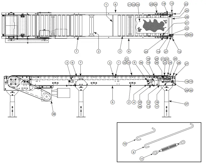
| Ref. No. | Part No. | Description |
| 1 2 | B-05477 B-03916 | Threaded Section Spacer (Specify BR) Bed Spacer (Specify BR) |
| 3 4 | B-01982 B-03894 | 1.9 in. Dia. Galvanized Return Roller (Specify BR) 2-1/8 in. Dia. Snub Roller (Specify BR) |
| 5 | B-00944 | 7/16 in. Hex Idler Bracket |
| 6 | — | Frame Channel—3 in. Roller Centers |
| — | B-04923 | 4’ Long |
| — | B-02636 | 5’ Long |
| — | B-05494 | 6’ Long |
| — | B-21606 | 7’ Long |
| — | B-12082 | 7’ 6” Long |
| — | B-09908 | 8’ Long |
| — | B-21607 | 9’ Long |
| — | B-02633 | 10’ Long |
| 7 | B-23316 | Splice Plate |
| 8 | 040.302 | 3/8-16 x 3/4”Lg. Hex Head Cap Screw(Not Shown) |
| 9 | 044.120 | Cross Brace Rod – 70” Long |
| 10 | 044.121 | Cross Brace Rod – 6” Long |
| 11 | 049.308 | Turnbuckle |
| 12 | — | Take-Up Channel—LH |
| — | B-20427 | 4 in. Tail Pulley |
| — | B-20431 | 6 in. Tail Pulley |
| 13 | — | Take-Up Channel—RH |
| — | B-20426 | 4 in. Tail Pulley |
| — | B-20430 | 6 in.Tail Pulley |
| 14 | — | Take-Up Plate—LH |
| — | B-14538-L | 4 in. Tail Pulley |
| — | B-14545 | 6 in. Tail Pulley |
| 15 | — | Take-Up Plate—RH |
| — | B-14538-R | 4 in. Tail Pulley |
| — | B-14545 | 6 in. Tail Pulley |
| 16 | B-14624 | Spacer |
| 17 | B-14623 | Guide Bar |
| Ref. No. | Part No. | Description |
| 18 | 093.215 | Roller Bracket |
| 19 | B-14743 | End Roller (Specify BR) |
| 20 | — | Tail Pulley |
| — | B-22323 | 4 in. Dia. 16 in. thru 30 in. OAW (Specify) |
| — | B-21755 | 6 in. Dia. 36 in. thru 54 in. OAW (Specify) |
| 21 | — | Nip Point Guard |
| — | B-21158 | 4 in. Dia. 16 in. thru 30 in. OAW (Specify) |
| — | B-21771 | 6 in. Dia. 36 in. thru 54 in. OAW (Specify) |
| 22 | — | Nip Point Mounting Bracket – LH |
| — | B-14533-L | 4 in. Tail Pulley |
| — | B-14535-L | 6 in. Tail Pulley |
| 23 | — | Nip Point Mounting Bracket – RH |
| — | B-14533-R | 4 in. Tail Pulley |
| — | B-14535-R | 6 in. Tail Pulley |
| 24 | — | 2-Bolt Flange Bearing |
| — | 010.0021 | 4 in. Pulley—1 in. Bore |
| — | 010.003 | 6 in. Pulley—1-3/16 in. Bore |
| 25 | — | Take-Up Bolt |
| — | 040.407 | 1/2-13 x 4 in. Long (4 in. Pulley) |
| — | 040.4061 | 1/2-13 x 3 in. Long (6 in. Pulley) |
| 26 | 041.201 | Hex Jam Nut, 1/2-13 |
| 27 | 090.262 | Pop-Out Roller Bracket |
| 28 | B-20445 | 1.9 in. Dia. Pop-Out Roller (Specify BR) |
| 29 | 090.107 | Small Hog Ring |
| 30 | 091.110 | Cable Assembly |
| 31 | — | Belt, Black Ultimate 140 BOS (Specify Width) |
| 32 | — | U3 Clipper Unibar Lacing |
| 33 | — | #13 Lacing Pin |
| 34 | B-12758 | Snub Roller Guards (Specify BR) |
| 35 | B-22350 | Snub Roller Guard Mounting Bracket |
| 36 | 049.310 | U-Type Speed Nut, 1/4-20 |
| 37 | — | MS Type Support Assembly (Specify Elevation) |
| 38 | B-08376 | End Drive Assembly (Specify BR) (See pg. 13) |
8” End Drive Assembly
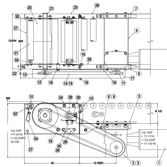
| Ref. No. | Part No. | Description |
| 1 | — | Motor-C-Face |
| — | 030.7134 | 1/2 HP—230/460 VAC—3 Ph.—60 Hz.—TEFC |
| — | 030.7324 | 1 HP—230/460 VAC—3 Ph.—60 Hz.—TEFC |
| — | 030.7534 | 2 HP—230/460 VAC—3 Ph.—60 Hz.—TEFC |
| 2 | — | Speed Reducer** |
| — | R-00153-30R | 4AC—RH—30:1 Ratio |
| — | R-00164-30R | 5AC—RH—30:1 Ratio |
| 3 | — | Coupling Kit-Motor To Reducer |
| — | 052.145 | 1/2 — 1 HP |
| — | 052.146 | 1-1/2 — 2 HP |
| 4 | WA-015546 | Motor Base Amendment (Specify PAW) |
| 5 | PT-060063 | Reinforcement Bar – 13 in. Long |
| 6 | B-24677 | Motor Base Support Angle – LH |
| 7 | B-24678 | Motor Base Support Angle – RH |
| 8 | 040.307 | Motor Base Take-Up Bolt—3/8-16 x 2-1/4 in. Long |
| 9 | 041.300 | Motor Base Hex Jam Nut—Heavy-3/8-16 |
| 10 | B-03191 | Butt Coupling Angle |
| 11 | — | Sprocket-Reducer** |
| — | 028.133 | 50B14 x 1 in. Bore (4AC) |
| — | 028.1342 | 50B16 x 1-1/4 in. Bore (5AC) |
| 12 | — | Sprocket—Drive Pulley** |
| — | 028.13832 | 50B 28 x 1-7/16 in. Bore (4AC) |
| — | 028.1115 | 50B 32 x 1-7/16 in. Bore (5AC) |
| 13 | 090.203 | Shaft Key—1/4 in. Sq. x 1 in. Long |
| 14 | 029.101 | #50 Riveted Roller Chain |
| 15 | 029.201 | Connector Link—#50 Roller Chain |
| 16 | B-07936 | Chain Guard Back Plate |
| 17 | B-07939 | Chain Guard Front Plate Weldment |
| 18 | 098.168 | Chain Guard Spacer |
| 19 | 041.919 | Acorn Nut, 3/8-16 |
| 20 | B-02021 | 8 in. Dia. Ctr. Dr. Pulley (Fully Lagged) (Specify OAW) |
| 21 | 010.202 | 4-Bolt Flange Bearing—1-3/16 in. Bore |
| 22 | B-21121-L | Drive Support Channel – LH |
| 23 | B-21121-R | Drive Support Channel – RH |
| 24 | B-13097 | Slider Guard (Specify BR) |
| 25 | B-07930 | Drive Gusset Angle – LH |
| 26 | B-07931 | Drive Gusset Angle – RH |
| 27 | B-05477 | Threaded Section Spacer (Specify BR) |
| 28 | B-03916 | Bed Spacer (Specify BR) |
| 29 | B-17254 | 2-1/2 in. Dia. Heavy Duty Snub Idler (Specify BR) |
| 30 | B-04842 | 11/16 in. Hex Idler Bracket |
| 31 | B-20445 | 1.9 in. Dia. Pop-Out Roller (Specify BR) |
| 32 | 090.262 | Pop-Out Roller Bracket – Molded |
| 33 | 090.107 | Small Hog Ring |
| 34 | 091.110 | Cable Assembly |
| 35 | B-12349 | Snub Roller Guard (Specify BR) |
| 36 | B-12346 | Mounting Bracket, Snub Roller Guard |
| 37 | 049.310 | U-Type Speed Nut-1/4-20 |
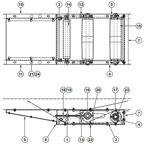
Underside Take-Up Assembly
“Building Relationships One Conveyor Part at a Time”
| Ref. No. | Part No. | Description |
| 1 | B-04842 | Mounting Bracket – 11/16 in. Hex Idler |
| 2 | B-05477 | Threaded Section Spacer (Specify BR) |
| 3 | B-05966 | Upper Bearing Guide |
| 4 | B-07987 | Bearing Spacer – 3 Bolt Flange Bearing, 1 in. B |
| 5 | B-09844-L | Side Channel Assembly – LH, Low Profile Take-Up |
| 6 | B-09844-R | Side Channel Assembly – RH, Low Profile Take-Up |
| 7 | B-09848 | Rear Guard – 4 in. Low Profile Take-Up (Specify OAW) |
| 8 | B-09849 | Bottom GD – 4 in. Low Profile Take-Up (Specify OAW) |
| 9 | B-09850 | BTM Angle GD – 4 in. Low Profile Take-Up (Specify OAW) |
| 10 | B-09851-L | Side Guard – LH 4 in. Low Profile Take-Up |
| 11 | B-09851-R | Side Guard – RH 4 in. Low Profile Take-Up |
| 12 | B-09852-L | Take-Up Plate Assembly – LH Low Profile |
| 13 | B-09852-R | Take-Up Plate Assembly – RH Low Profile |
| 14 | B-17254 | 2-1/2 in. OD Snub Rlr Assembly-BCA BRG (Specify BR) |
| 15 | — | 4 in. Dia. Pulley Assembly – System Ends (Specify OAW) |
| — | B-22323 | 10 in. thru 18 in. OAW (Specify) |
| — | B-05904 | 20 in. thru 42 in. OAW (Specify) |
| 16 | 010.0021 | Bearing – Cast Iron, 2-Bolt, 1 in. Bore |
| 17 | 010.102 | Bearing – Cast Iron, 3-Bolt, 1 in. Bore |
| 18 | 040.411 | 1/2-13 x 9 in. Lg. Hex Bolt-Fully Threaded |
| 19 | 041.201 | 1/2-13 NC2B Hex Jam Nut |
| 20 | 042.2009 | 5/16-18 x 1 in. Lg. Flat head Bolt |
| 21 | 042.300 | 1/4-20 x 1/2 in. Lg Truss Head Bolt |
| 22 | 040.302 | 3/8-16 x 3/4 in. Lg Hex Bolt |
| 23 | 042.557 | 5/16-18 x 1-1/4 in. Lg Carriage Bolt |
| 24 | 049.310 | 1/4-20 U-Type Speed Nut |
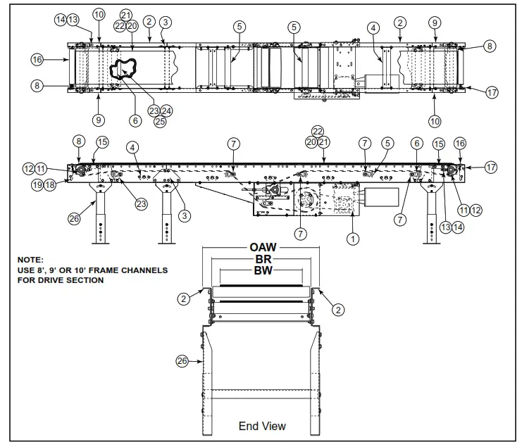
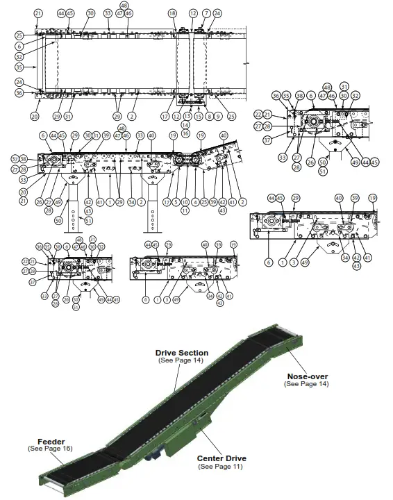
Model RBI Parts Drawing
NOTE:
USE 8’, 9’, OR 10’ FRAME CHANNELS FOR DRIVE SECTION
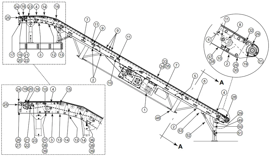
Model RBI Parts List
| Ref. No. | Part No. | Description |
| 1 | — | Drive Assembly (See Page 11) |
| 2 | A/R | Frame Channel (See RB Assy Page 10) |
| 3 | B-20051 | 1’ Long Channel |
| 4 | B-22239 | Slider Pan, 10-1/2” Long (Specify BR) |
| 5 | B-23316 | Splice Plate |
| 6 | 040.302 | 3/8-16 x 3/4” Lg. Hex Head Cap Screw (Not Shown) |
| 7 | B-03916 | Bed Spacer (Specify BR) |
| 8 | B-05477 | Threaded Section Spacer (Specify BR) |
| 9 | B-01982 | 1.9 in. Dia. Galvanized Roller (Specify BR) |
| 10 | B-03894 | 2-1/8 in. Dia. Snub Roller |
| 11 | B-00944 | 7/16 in. Hex Idler Bracket |
| 12 | — | Nose-Over Channel |
| — | B-05472 | 12 in. Nose-Over |
| — | B-05471 | 24 in. Nose-Over |
| 13 | B-01538 | Nose-Over Splice Plate |
| 14 | G-00472 | 2-1/2 in. Dia. Nose-Over Roller (Specify BR) |
| 15 | B-05490 | Nose-Over Roller Bracket |
| 16 | — | Tail Pulley |
| — | B-22323 | 4 in. Dia.—16 in. thru 28 in. OAW (Specify) |
| — | B-21755 | 6 in. Dia.—30 in. thru 42 in. OAW (Specify) |
| 17 | — | System End Channel—R.H. |
| — | B-20441 | 4 in. Pulley, 16 in. thru 28 in. OAW (Specify) |
| — | B-20443 | 6 in. Pulley, 30 in. thru 42 in. OAW (Specify) |
| 18 | — | System End Channel—L.H. |
| — | B-20442 | 4 in. Pulley, 16 in. thru 28 in. OAW (Specify) |
| — | B-20444 | 6 in. Pulley, 30 in. thru 42 in. OAW (Specify) |
| 19 | — | 3-Bolt Flange Bearing |
| — | 010.102 | 4 in. Pulley—1 in. Bore |
| — | 010.103 | 6 in. Pulley—1-3/16 in. Bore |
| 20 | — | Bearing Spacer |
| — | B-14455 | 1 in. Bore |
| — | B-14456 | 1-3/16 in. Bore |
| 21 | 040.4041 | Take-Up Bolt 1/2-13 x 2 in. Long |
| 22 | 041.201 | Hex Jam Nut, 1/2-13 |
| 23 | — | Slider Plate |
| — | B-09945 | 4 in. Pulley |
| — | B-21155 | 6 in. Pulley |
| 24 | B-20445 | 1.9 in. Dia. Pop-Out Roller (Specify BR) |
| 25 | 090.262 | Pop-Out Roller Bracket |
| 26 | 091.110 | Cable Assembly |
| 27 | 090.107 | Small Hog Ring |
| 28 | — | Tail Pulley (Round End) |
| — | B-22221 | 4 in. Dia. 16 in. thru 28 in. OAW (Specify) |
| — | B-21752 | 6 in. Dia. 30 in. thru 42 in. OAW (Specify) |
| Ref. No. | Part No. | Description |
| 29 | — | Drive Plate R.H. (Round End) |
| — | B-09813-R | 4 in. Pulley |
| — | B-09758-R | 6 in. Pulley |
| 30 | — | Drive Plate L.H. (Round End) |
| — | B-09813-L | 4 in. Pulley |
| — | B-09758-L | 6 in. Pulley |
| 31 | — | Bearing Spacer (Round End) |
| — | B-07987 | 4 in. Pulley |
| — | B-02042 | 6 in. Pulley |
| 32 | — | Nip Point Guard (Round End) |
| — | B-18909 | 4 in. Pulley 16 in. thru 28 in. OAW (Specify) |
| — | B-18910 | 6 in. Pulley 30 in. thru 42 in. OAW (Specify) |
| 33 | — | Belt, Black Trackmate 447 Roughtop w/PVC Cover (Specify Width) |
| 34 | — | U3 Clipper Unibar Lacing |
| 35 | — | #13 Lacing Pin |
| 36 | B-12758 | Snub Roller Guards (Specify BR) |
| 37 | B-22350 | Snub Roller Guard Mounting Plate |
| 38 | 049.310 | U-Type Speed Nut, 1/4-20 |
| 39 | — | Underside Bed Cover—Intermediate (Not Shown) |
| — | B-11101 | 12 in. thru 60 in. Long—13 in. thru 19 in. BR (Specify Length & BR) |
| — | B-11103 | 12 in. thru 60 in. Long—21 in. thru 39 in. BR (Specify Length & BR) |
| 40 | — | Underside Bed Cover—Tail (Not Shown) |
| — | B-11102 | 18 in. thru 66 in. Long—13 in. thru 19 in. BR (Specify Length & BR) |
| — | B-11104 | 18 in. thru 66 in. Long—21 in. thru 39 in. BR (Specify Length & BR) |
| 41 | B-11107 | Support Bar—13 in. thru 39 in. BR (Specify BR) (Not Shown) |
| 42 | — | Fully Threaded Rod—5/8-11 |
| — | 044.1073 | 4’ Long |
| — | 044.1075 | 6’ Long |
| — | 044.108 | 8’ Long |
| — | 044.109 | 10’ Long |
| — | 044.110 | 12’ Long |
| 43 | B-01274 | Under Support (Specify OAW) |
| 44 | B-01283 | Base Plate |
| 45 | B-03854 | Pipe Retainer |
| 46 | 041.600 | Hex Jam Lockout, 2-Way—5/8-11 |
| 47 | — | Under trussing (See Page 35,36) |
| 48 | — | MS Type Support Assembly (Specify Elevation) |
| 51 | — | Knee Brace |
| — | B-00303 | 36 in. Long |
| — | B-00705 | 27 in. Long |
| 52 | B-01717 | Knee Brace Bracket |
| 53 | B-06036 | Support Splice Channel A/R (Not Shown) |
Model RBI Powered Feeder Parts List
| Ref. No. | Part No. | Description |
| 1 | — | Frame Channel |
| — | B-21868 | 18 in. Long |
| — | B-21170 | 33 in. Long |
| — | B-04923 | 48 in. Long |
| — | B-02636 | 60 in. Long |
| — | B-05494 | 72 in. Long |
| 2 | B-22239 | Slider Pan 10-1/2 in. Lg (Specify BR) |
| 3 | B-22241 | Slider Pan 16-1/2 in. Lg for 18 in. Lg Section (Specify BR) |
| 4 | — | Conveyor Tail Pulley (Specify OAW) |
| — | B-22222 | 4 in. Pulley, 16 in. thru 28 in. OAW (Specify) |
| — | B-22101 | 6 in. Pulley, 30 in. thru 42 in. OAW (Specify) |
| 5 | — | Feeder Drive Pulley (Specify OAW) |
| — | B-22222 | 4 in. Pulley, 16 in. thru 28 in. OAW (Specify) |
| — | B-22101 | 6 in. Pulley, 30 in. thru 42 in. OAW (Specify) |
| 6 | — | Feeder Tail Pulley |
| — | B-22323 | 4 in. Pulley, 16 in. thru 28 in. OAW (Specify) |
| — | B-21755 | 6 in. Pulley, 30 in. thru 42 in. OAW (Specify) |
| 7 | — | 3-Bolt Flange |
| — | 010.102 | 1 in. Bore (4 in. Pulley) |
| — | 010.103 | 1-3/16 in. Bore (6 in. Pulley) |
| 8 | — | Sprocket |
| — | 028.133 | 50B14 x 1 in. Bore (4 in. Pulley) |
| — | 028.1341 | 50B16 x 1-3/16 in. Bore (6 in. Pulley) |
| 9 | 090.203 | Shaft Key, 1/4 in. Sq. x 1 in. Long |
| 10 | 029.101 | #50 Riveted Roller Chain |
| 11 | 029.202 | #50 Connector Link |
| 12 | — | Pivot Plate |
| — | B-06168 | 4 in. Pulley |
| — | B-06172 | 6 in. Pulley |
| 13 | 040.3122 | Hex Head Bolt, 3/8-16 x 4 in. Long (4 in. Pulley Only) |
| 14 | 041.200 | Hex Jam Nut, 3/8-16 |
| 15 | — | Chain Guard |
| — | B-06174-001 | 4 in. Pulley |
| — | B-06179-001 | 6 in. Pulley |
| 16 | 041.919 | Acorn Nut—3/8-16 |
| 17 | — | Conveyor Take-Up & Feeder Drive Plate—R.H. |
| — | B-09813-R | 4 in. Pulley |
| — | B-09758-R | 6 in. Pulley |
| 18 | — | Conveyor Take-Up & Feeder Drive Plate—L.H. |
| — | B-09813-L | 4 in. Pulley |
| — | B-09758-L | 6 in. Pulley |
| 19 | — | Nip Point Guard |
| — | B-18909 | 4 in. Pulley (Specify BR) |
| — | B-18910 | 6 in. Pulley (Specify BR) |
| 20 | — | Feeder Take-Up Channel—R.H. |
| — | B-20426 | 4 in. Pulley |
| — | B-20430 | 6 in. Pulley |
| Ref. No. | Part No. | Description |
| 21 | — | Feeder Take-Up Channel—L.H. |
| — | B-20427 | 4 in. Pulley |
| — | B-20431 | 6 in. Pulley |
| 22 | — | Mounting Bracket—R.H. |
| — | B-14533-R | 4 in. Pulley |
| — | B-14535-R | 6 in. Pulley |
| 23 | — | Mounting Bracket—L.H. |
| — | B-14533-L | 4 in. Pulley |
| — | B-14535-L | 6 in. Pulley |
| 24 | — | Take-Up Plate—R.H. |
| — | B-14538-R | 4 in. Pulley |
| — | B-14545 | 6 in. Pulley |
| 25 | — | Take-Up Plate—L.H. |
| — | B-14538-L | 4 in. Pulley |
| — | B-14545 | 6 in. Pulley |
| 26 | — | 2-Bolt Flange Bearing |
| — | 010.0021 | 1 in. Bore (4 in. Pulley) |
| — | 010.003 | 1-3/16 in. Bore (6 in. Pulley) |
| 27 | B-14624 | Spacer |
| 28 | B-14623 | Guide |
| 29 | B-01982 | 1.9 in. Dia. Galvanized Roller (Specify BR)(4 in. Pulley Only) |
| 30 | B-14743 | 1.9 in. Dia. Galvanized Roller (Specify OAW) |
| 31 | 093.215 | Return Roller Bracket |
| 32 | — | Nip Point Guard (Specify OAW) |
| — | B-21158 | 4 in. Pulley |
| — | B-21771 | 6 in. Pulley |
| 33 | B-05477 | Threaded Section Spacer (Specify OAW) |
| 34 | B-03916 | Bed Spacer (Specify OAW) |
| 35 | B-20445 | 1.9 in. Dia. Pop-Out Roller (Specify BR) |
| 36 | 090.262 | Pop-Out Roller Bracket |
| 37 | 091.110 | Cable Assembly |
| 38 | 090.107 | Hog Ring |
| 39 | B-03894 | 2-1/8 in. Snub Roller (Specify BR) |
| 40 | B-00944 | 7/16 in. Hex Idler Bracket |
| 41 | B-12758 | Snub Roller Guard (Specify BR) |
| 42 | B-22350 | Snub Roller Guard Mounting Bracket |
| 43 | 049.310 | U-Type Speed Nut, 1/4-20 |
| 44 | — | Take-Up Bolt |
| — | 040.407 | 1/2-13 x 4 in. Long (4 in. Pulley) |
| — | 040.4061 | 1/2-13 x 3 in. Long (6 in. Pulley) |
| 45 | 041.201 | Hex Jam Nut, 1/2-13 |
| 46 | — | Belt, Black Ultimate 140 BOS (Specify Width) |
| 47 | — | #2 Clipper Unibar Lacing (Specify Length) |
| 48 | — | 3/32 Lacing Pin |
| 49 | B-16659 | MS Type Support Assembly |
Model RBI Powered Feeder Parts Drawing
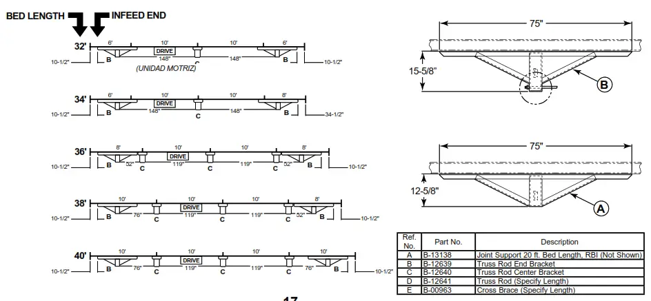
Under trussing—Model RBI
Under trussing—Model RBI
Planned Maintenance Checklist
| Component | Suggested Action | Schedule | ||
| Weekly | Monthly | Quarterly | ||
| Motor | Check Noise | |||
| Check Temperature | ||||
| Check Mounting Bolts | ||||
| Reducer | Check Noise | |||
| Check Temperature | ||||
| Check Oil Level | ||||
| Drive Chain | Check Tension | |||
| Lubricate | ||||
| Check for Wear | ||||
| Sprockets | Check for Wear | |||
| Check Set Screws & Keys | ||||
| Belt | Check Tracking | |||
| Check Tension | ||||
| Check Lacing | ||||
| Bearings (Pulleys & Rollers) | Check Noise | |||
| Check Mounting Bolts | ||||
| V-Belts | Check Tension | |||
| Check for Wear | ||||
| Check Sheave Alignment | ||||
| Structural | General Check: All loose bolts, etc., tightened | |||
![]() [email protected]
[email protected]
www.HytrolParts.com


