![]()
IMPORTANT!
¡IMPORTANTE!
DO NOT DESTROY NO DESTRUIR
Installation and Maintenance
Manual with Safety Information and Parts List
RECOMMENDED SPARE PARTS HIGHLIGHTED IN GRAY 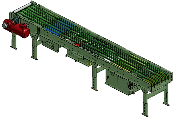
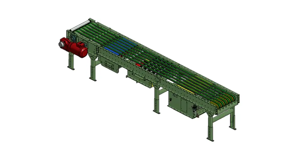
Model ProSort MRT
Effective November 2013
(Supercedes October 2007) Bulletin #656
Use code HYPMANUAL for free shipping on your first order at HytrolParts.com
INTRODUCTION
This manual provides guidelines and procedures for installing, operating, and maintaining your conveyor.
A complete parts list is provided with recommended spare parts highlighted in gray. Important safety information is also provided throughout the manual. for safety to personnel and for proper operation of your conveyor, it is recommended that you read and follow the instructions provided in this manual.
• Receiving and Uncrating
- Check the number of items received against the bill of lading.
- Examine condition of equipment to determine if any damage occurred during shipment.
- move all crates to area of installation.
- Remove crating and check for optional equipment that may be fastened to the conveyor. make sure these parts (or any foreign pieces) are removed.
NOTE: If damage has occurred or freight is missing, Contact your Hytrol Integration Partner.
- How to Order Replacement Parts
Included in this manual are parts drawings with complete replacement parts lists. minor fasteners, such as nuts and bolts, are not included.
When ordering replacement parts:
- Contact dealer from whom conveyor was purchased or nearest HYTROL Integration Partner.
- Give Conveyor model Number and Serial Number or HYTROL factory Order Number.
- Give Part Number and complete description from Parts List.
- Give type of drive. Example—8” End drive, 8” Center drive, etc.
- If you are in a breakdown situation, tell us.
Hytrol Conveyor
Company, Inc.
JONESBORO, ARKANSAS
SERIAL # 978747HYTROL Serial Number
(Located near drive on Powered models).
SAFETY INFORMATION
• Installation
GUARdS ANd GUARdING
Interfacing of Equipment. When two or more pieces of equipment are interfaced, special attention shall be given to the interfaced area to insure the presence of adequate guarding and safety devices. Guarding Exceptions. Whenever conditions prevail that would require guarding under these standards, but such guarding would render the
conveyor unusable, prominent warning means shall be provided in the area or on the equipment in lieu of guarding.
Guarded by Location or Position. Where necessary for the protection of employees from hazards, all exposed moving machinery parts that present a hazard to employees at their work station shall be mechanically or electrically guarded, or guarded by location or position.
- Remoteness from frequent presence of public or employed personnel shall constitute guarding by location.
- When a conveyor passes over a walkway, roadway, or work station, it is considered guarded solely by location or position if all moving parts are at least 8 ft. (2.44 m) above the floor or walking surface or are otherwise located so that the employee cannot inadvertently come in contact with hazardous moving parts.
- Although overhead conveyors may be guarded by location, spill guards, pan guards, or equivalent shall be provided if the product may fall off the conveyor for any reason and if personnel would be endangered.
HEAdROOm
- When conveyors are installed above exit passageways, aisles, or corridors, there shall be provided a minimum clearance of 6 ft. 8 in. (2.032 m) measured vertically from the floor or walking surface to the lowest part of the conveyor or guards.
- Where system function will be impaired by providing the minimum clearance of 6 ft. 8 in. (2.032 m) through an emergency clearance, alternate passageways shall be provided.
- It is permissible to allow passage under conveyors with less than 6 ft. 8 in. (2.032 m) clearance from the floor for other than emergency exits if a suitable warning indicates low headroom.
Operation
A) Only trained employees shall be permitted to operate conveyors.
Training shall include instruction in operation under normal conditions and emergency situations.
B) Where employee safety is dependent upon stopping and/or starting devices, they shall be kept free of obstructions to permit ready access.
C) The area around loading and unloading points shall be kept clear of obstructions which could endanger personnel.
d) No person shall ride the load-carrying element of a conveyor under any circumstances unless that person is specifically authorized by the owner or employer to do so. Under those circumstances, such employee shall only ride a conveyor which incorporates within its supporting structure platforms or control stations specifically designed
for carrying personnel. Under no circumstances shall any person ride on any element of a vertical conveyor.
E) Personnel working on or near a conveyor shall be instructed as to the location and operation of pertinent stopping devices.
f) A conveyor shall be used to transport only material it is capable of handling safely.
G) Under no circumstances shall the safety characteristics of the conveyor be altered if such alterations would endanger personnel.
H) Routine inspections and preventive and corrective maintenance programs shall be conducted to insure that all safety features and devices are retained and function properly.
I) Personnel should be alerted to the potential hazard of entanglement in conveyors caused by items such as long hair, loose clothing, and jewelry.
J) Conveyors shall not be maintained or serviced while in operation unless proper maintenance or service requires the conveyor to be in motion. In this case, personnel shall be made aware of the hazards and how the task may be safely accomplished.
K) Owners of conveyor should insure proper safety labels are affixed to the conveyor warning of particular hazards involved in operation of their conveyors.
CAUTION! Because of the many moving parts on the conveyor, all personnel in the area of the conveyor need to be warned that the conveyor is about to be started.
• Maintenance
- All maintenance, including lubrication and adjustments, shall be performed only by qualified and trained personnel.
- It is important that a maintenance program be established to All maintenance, including lubrication and adjustments, shall be insure that all conveyor components are maintained in a condition which does not constitute a hazard to personnel.
- When a conveyor is stopped for maintenance purposes, starting devices or powered accessories shall be locked or tagged out in accordance with a formalized procedure designed to protect all persons or groups involved with the conveyor against an unexpected start.
- Replace all safety devices and guards before starting equipment for normal operation.
- Whenever practical, dO NOT lubricate conveyors while they are in motion. Only trained personnel who are aware of the hazard of the conveyor in motion shall be allowed to lubricate.
Safety Guards
maintain all guards and safety devices IN POSITION and IN SAfE REPAIR.
Safety Labels
In an effort to reduce the possibility of injury to personnel working around HYTROL conveying equipment, safety labels are placed at various points on the equipment to alert them of potential hazards. Please check equipment and note all safety labels. make certain your personnel are alerted to and obey these warnings. See Safety manual for examples of warning labels.
REMEMBER do not remove, reuse or modify material handling equipment for any purpose other than it’s original intended use.
CAUTION! Only trained personnel should track a conveyor belt which must be done while conveyor is in operation. dO NOT attempt to track belt if conveyor is loaded.
INSTALLATION
• Support Installation
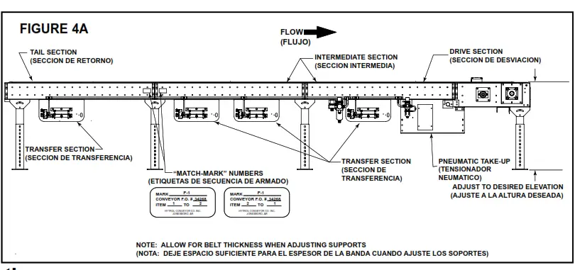
- determine primary direction of product flow. figure 4A indicates the preferred flow as related to the drive.
- Refer to “match-mark” numbers on ends of conveyor sections. (figure 4A) Position them in this sequence near the area of installation.
- Attach supports to both ends of drive section and to one end of intermediate or tail sections (figure 4A). Hand tighten bolts only at this time. Conveyors angle of incline will determine where the knee brace mounting brackets are to be placed when required.
- Adjust elevation to required height.

• Ceiling Hanger Installation
If conveyors are to be used in an overhead application, ceiling hangers may have been supplied in place of floor supports.
figure 4B shows how a ceiling hanger mounts to a conveyor section. Ceiling hangers should be mounted at section joints. for safety information concerning conveyors mounted overhead, refer to “Installation Safety Precautions” on Pg 3.
NOTE: When installing ceiling hanger rods in an existing building, all methods of attachment must comply with local building codes.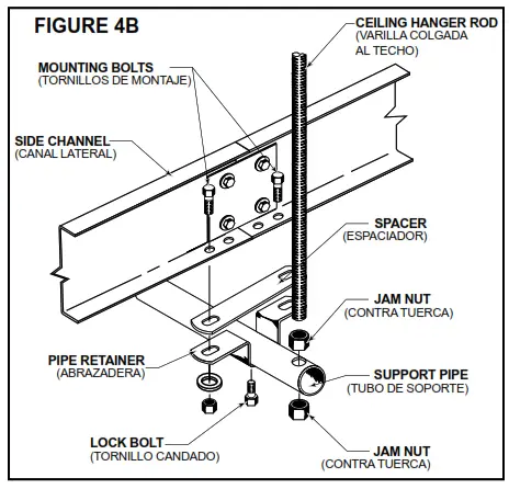
• Belt Installation
INSTALLING THE BELT
The conveyor drive belt is a green aramide continuous belt. To install belt follow directions below
WARNING: Do not install belt with power on, remove air to take-up .
NOTE: Belt will be wrapped around the discharge drive pulley
- Unroll belt while inserting into the bottom cut out of bed spacer and into the belt guide at top. Green conveying surface should be showing at top. make sure belt is not twisted in the process.
- Continue inserting belt from discharge to infeed. At infeed end remove bolt attaching belt guard to infeed idler weldment , Loosen bolt holding top flat belt idler to belt guard this will allow the guard to pivot which will make room for the belt to be wrapped around the top flat belt idler and snub over the bottom flat belt idler. Add bolt to belt guard and tighten top flat belt idler bolt (figure 4d).
- Next go to the pneumatic take-up near discharge end and thread belt through take-up as shown in (figure 5A).
BELT TENSION
Note: for maximum efficiency, maintain just enough belt tension so drive pulley will not slip when carrying the rated load. Over tightening of belts will cause premature failure.
• Conveyor Set-Up
- mark a chalk line on floor to locate center of the conveyor (floor mounted Conveyors).
- Place the drive section in position.
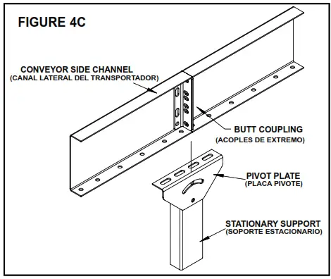
- Install remaining sections placing end without support on extend pivot plate of previous section (figure 4A). Check “match mark” Numbers to see that adjoining sections are in proper sequence

- fasten sectionstogether with butt couplingsand pivot plates(figure 4C). Handtighten bolts only.
- Check to see thatconveyor is levelacross width and lengthof unit. Adjust supportsand ceiling hangers asnecessary.
- Install electrical controlsand wire motor.See page 7.
PNEUMATIC TAKE-UP:
The window guard can be removed to reveal the take-up idler position. The pneumatic take-up can be adjusted by increasing the pressure at the filter regulator (see fig. 5A). Then operating pressure will be determined by the total length and unit load. Start with the pressure set at 20 psi. Increase by 2 psi until the drive pulley does not slip when carrying the rated load up to 30 psi. Replace all guards before operating.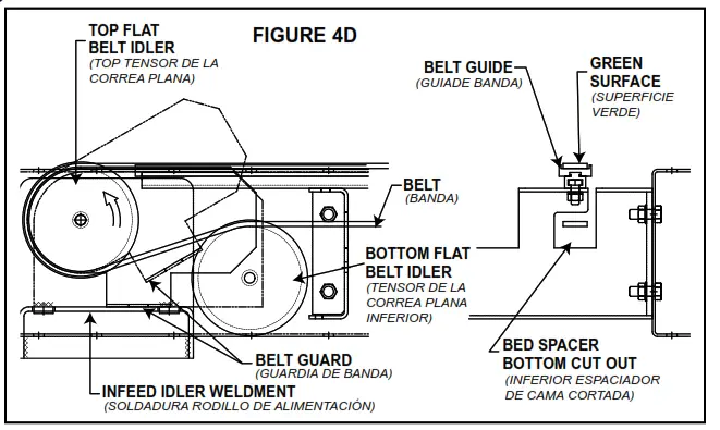
• Belt Installation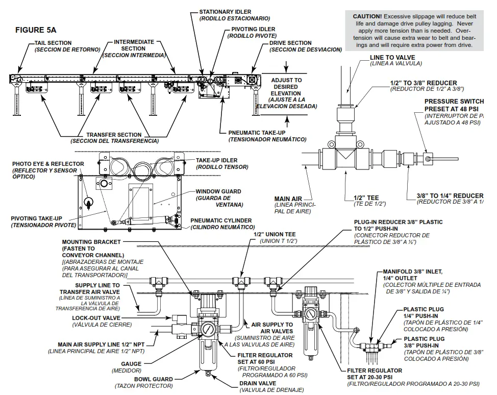
• Belt Replacement
WARNING: Do not replace belt with power on, remove air to take-up.
- Remove (4) bolts holding wear strip support channel in place and remove channel by sliding toward discharge end of conveyor. (figure 5B)
- Remove top belt tran angle holding rollers in place
- Remove 1-3/8” dia. rollers
- Remove bearing support channel and bearing by removing hardware securing bearing support channel to drive channel. Next loosen set screw securing bearing to drive
pulley shaft. Remove support channel and bearing - Thread belt around pulley.
- Unroll belt while inserting into the bottom cut out of bed spacer and into the belt guide at top. Green conveying surface should be showing at top. make sure belt is
not twisted in the process. - Continue inserting belt from discharge to infeed. At infeed end remove bolt attaching belt guard to infeed idler weldment, loosen bolt holding top flat belt idler to
belt guard this will allow the guard to pivot which will make room for the belt to be wrapped around the top flat belt idler and snub over the bottom flat belt idler.
Add bolt to belt guard and tighten top flat belt idler bolt (figure 4d). - Assemble 1-3/8” dia. Rollers along with top belt tran angle
- Assemble wear strip support channel.
- Reattach bearing support channel with bearing . tighten set screw in bearing.
- Next go to the pneumatic take-up near discharge end and thread belt through take-up as shown in (figure 5A).
“Building Relationships One Conveyor Part at a Time”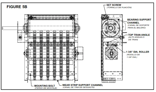
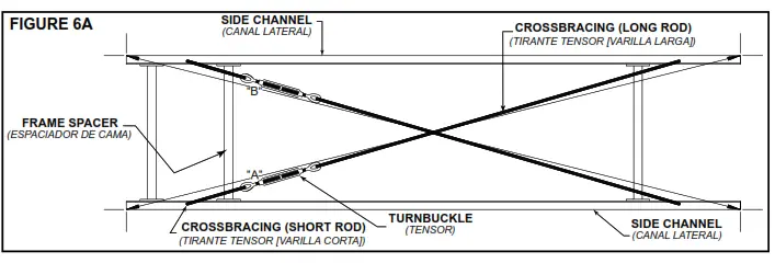
• Racked Sections
It is important that each bed section be checked for a “racked” or outof-square condition. If conveyor is not square, tracking problems will result. figure 6A indicates a racked
section.
TO CORRECT AN OUT-OfSQUARE SECTION
- Locate points on corners of section and measure distance “A” & “B”. If the dimensions are not equal, the section will need to be squared. (figure 6A).
- Use crossbracing supplied on underside of conveyor to square each section. Adjust turnbuckle until dimensions “A” & “B” are equal.
- After all bed sections have been checked and corrected for “racked condition”, tighten all butt couplings and pivot plate bolts.
- make final check to see that all conveyor sections are level across width and length. If entire conveyor is level, supports can be lagged to floor.
OPERATION
• Conveyor Start-Up
Before conveyor is turned on, check for foreign objects that may have been left inside conveyor during installation. These objects could cause serious damage during start-up. After conveyor has been turned on and is operating, check motors, reducers, and moving parts to make sure they are working freely.
MAINTENANCE
• Electrical Equipment
CAUTION!
Because of the many moving parts on the conveyor, all personnel in the area of the conveyor need to be warned that the conveyor is about to be started.
WARNING! Electrical controls shall be installed and wired by a qualified electrician. Wiring information for the motor and controls are furnished by the equipment manufacturer.
CONTROLS
Electrical Code: All motor controls and wiring shall conform to the National Electrical Code (Article 670 or other applicable articles) as published by the National fire Protection Association and as approved by the American Standards Institute, Inc.
CONTROL STATIONS
A) Control stations should be so arranged and located that the operation of the equipment is visible from them, and shall be clearly marked or labeled to indicate the function controlled.
B) A conveyor which would cause injury when started shall not be started until employees in the area are alerted by a signal or by a designated person that the conveyor is about to start. When a conveyor would cause injury when started and is automatically controlled or must be controlled from a remote location, an audible device shall be provided which can be clearly heard at all points along the conveyor where personnel may be present. The warning device shall be actuated by the controller device starting the conveyor and shall continue for a required period of time before the conveyor starts. A flashing light or similar visual warning may be used in conjunction with or in place of the audible device if more effective in particular circumstances.
Where system function would be seriously hindered or adversely affected by the required time delay or where the intent of the warning may be misinterpreted (i.e., a work
area with many different conveyors and allied devices), clear, concise, and legible warning shall be provided. The warning shall indicate that conveyors and allied equipment may be started at any time, that danger exists, and that personnel must keep clear. The warnings shall be provided along the conveyor at areas not guarded by position or location.
C) Remotely and automatically controlled conveyors, and conveyors where operator stations are not manned or are beyond voice and visual contact from drive areas, loading areas, transfer points, and other potentially hazardous locations on the conveyor path not guarded by location, position, or guards, shall be furnished with emergency stop buttons, pull cords, limit switches, or similar emergency stop devices.
All such emergency stop devices shall be easily identifiable in the imme- diate vicinity of such locations unless guarded by location, position, or guards.
Where the design, function, and operation of such conveyor clearly is not hazardous to personnel, an emergency stop device is not required.
The emergency stop device shall act directly on the control of the conveyor concerned and shall not depend on the stopping of any other equipment. The emergency
stop devices shall be installed so that they cannot be overridden from other locations.
d) Inactive and unused actuators, controllers, and wiring should be removed from control stations and panel boards, together with obsolete diagrams, indicators, control
labels, and other material which serve to confuse the operator. SAfETY dEVICES
A) All safety devices, including wiring of electrical safety devices, shall be arranged to operate in a “fail-Safe” manner, that is, if power failure or failure of the device itself would occur, a hazardous condition must not result.
B) Emergency Stops and Restarts. Conveyor controls shall be so arranged that, in case of emergency stop, manual reset or start at the location where the emergency stop was initiated, shall be required of the conveyor(s) and associated equipment to resume operation.
C) Before restarting a conveyor which has been stopped because of an emergency, an inspection of the conveyor shall be made and the cause of the stoppage determined. The starting device shall be locked out before any attempt is made to remove the cause of stoppage, unless operation is necessary to determine the cause or to safely remove the stoppage. Refer to ANSI z244.1-1982, American National Standard for Personnel Protection – Lockout/Tagout of Energy Sources – minimum Safety Requirements and OSHA Standard Number 29 CfR 1910.147 “The Control of Hazardous Energy (Lockout/Tagout).”
• HyPower Cabling Installation
WARNING: Do not disconnect or connect any HyPower Cabling
Components while under power!
- All cabling connections are to be made without power on the system.
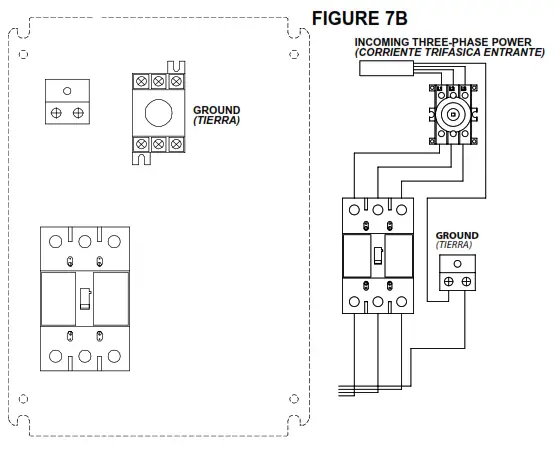
- Connect three-phase electrical service to disconnect box. A single-sided disconnect requires a 15 Amp service, double-sided disconnect requires a 30 Amp service. (See fig. 7A & 7B)
- from the disconnect box connect the HyPower Extension Cable(s) to the HyPower T-Connector.
- Connect the HyPower T-Connector to the male HyPower Cable that is pre-wired to the Vfd.
- Connect the female HyPower Cable on the Vfd to the male HyPower Cable pre-wired to the divert motor.
- Connect the remaining female connection on the T-Connector to the next divert zone on the conveyor and repeat steps 3 & 4 for each divert location.
IMPORTANT NOTE:
Electrical Code: All motor controls and wiring shall conform to the National Electrical Code (Article 670 or other applicable articles) as published by the National fire Protection Association and as approved by the American Standards Institute, Inc. Subject to local code and local customer acceptance.
• HyPower Cabling Installation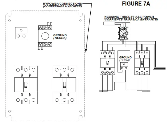
• HyPower Cabling Components
Single-Sided Disconnect Box This disconnect box has a 15 Amp service requirement and provides a disconnect means for up to 3 transfers at 230 volts or 6 transfers at 460 volts. The maximum distance for any motor from this disconnect box is 50’. Any distance over 50’ requires an additional inline disconnect. (See fig. 7B & 7C) Double-Sided Disconnect Box This disconnect box has a 30 Amp service requirement and provides a disconnect means for up to 6 transfers at 230 volts or 12 transfers at 460 volts. This disconnect box has the capability of covering 100’ of conveyor when located in the middle of the span. Any motor further than 50’ from the disconnect box requires an additional inline disconnect. (See fig. 7A & 7d)
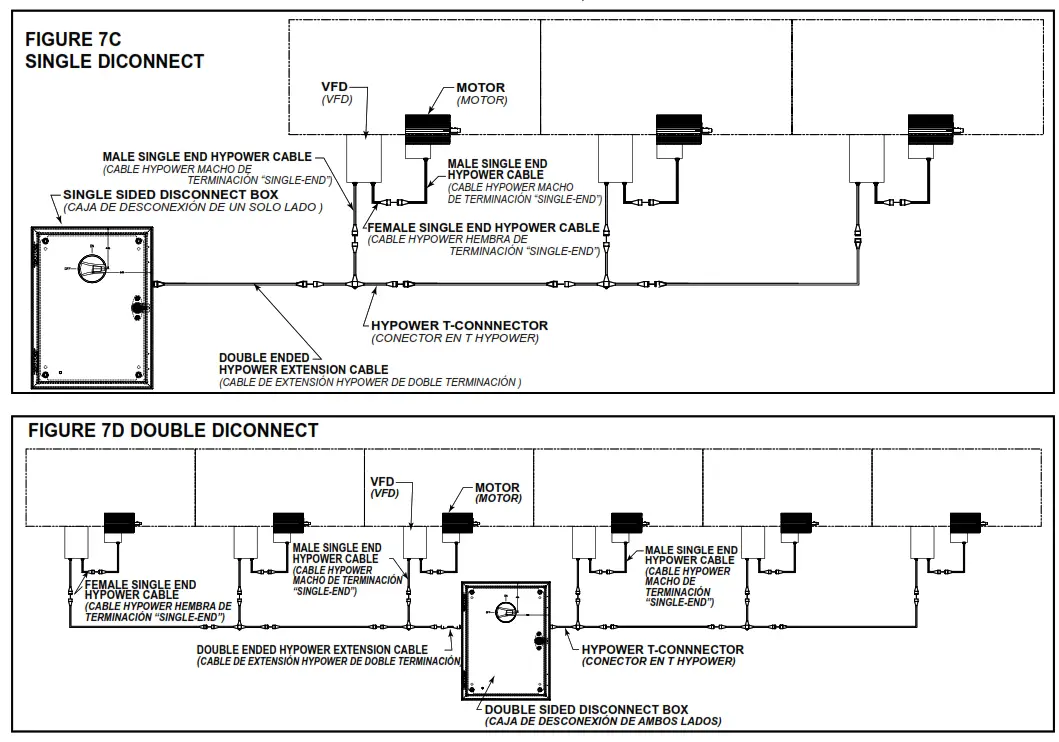
Double-Ended HyPower Extension Cable
Supplies power from the disconnect box down the conveyor to each HyPower T-Connector. (See fig. 7C & 7d)
HyPower T-Connector
Power is supplied to the T-Connector via the Extension Cable. The T-Connector is used as a power drop for each Variable frequency drive and motor. (See fig. 7C & 7d)
Male Single-End HyPower Cable
This cable will come pre-wired to each Variable frequency drive as well as to each divert motor. (See fig. 7C & 7d)
Female Single-End HyPower Cable
This cable will come pre-wired to each Variable frequency drive and supplies power to each divert motor from the Variable frequency drive. (See fig. 7C & 7d)
Transfer Adjustment
- The height of the transfer should be preset at factory.
- The height of the transfer may be adjusted to proper height by raising or lowering the cylinder-mounting channel. Loosen 3/8 in. bolts holding the cylindermounting
channel.Adjustusingjackbolts,tighten3/8in.bolts.
DRIVE BELT TENSION
- Loosen 3/8” locknut holding take-up idler, tension belt by pushing take-up idler down, hand tight should be adequate. Tighten the 3/8” locknut on take-up idler (See fig. 8A).
- To remove belt the drive rollers must be removed (See fig. 8A). Remove by pushing one side of the hex axle though the transfer support channel.
DRIVE ROLLER SPEED
To change the speed of the drive roller, turn round knob on the Vfd (variable frequency drive).
NOTE: All transfer motors are 230 volts AC. When supplying 460 volts to the Vfd, the drive will be programmed to have an output of 230 volts to the motors.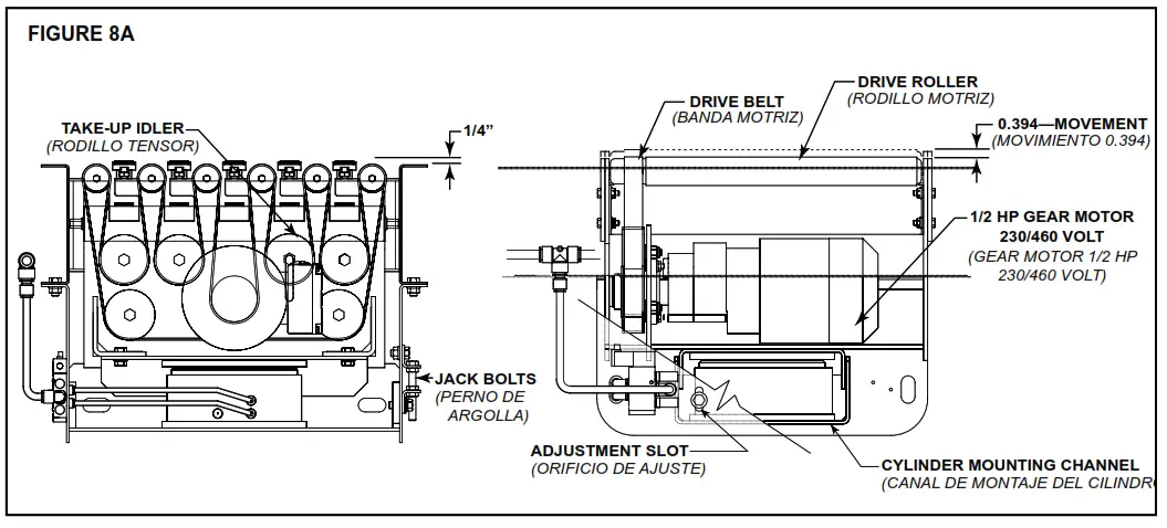
Trouble Shooting
TROUBLE SHOOTING DRIVES | ||
| TROUBLE | CAUSE | SOLUTION |
| Conveyor will not start or motor quits frequently. | 1) Motor is overloaded. 2) Motor is drawing too much current. | 1) Check for overloading of conveyor. 2) Check heater or circuit breaker and change if necessary |
| Drive belt wears exces- sively. | 1) Belt is too loose. | 1) Tighten belt. 2) Check pneumatic take-up (see below) |
| Loud popping or grind- ing noise. | 1) Defective bearing. | 1) Replace bearing. |
| Motor or reducer over- heating. | 1) Conveyor is overloaded. 2) Low voltage to motor. 3) Low lubricant level in reducer. | 1) Check capacity of conveyor and reduce load to recommended level. 2) Have electrician check and correct as necessary. 3) Relubricate per manufacturer’s recommendations. |
| Belt does not move, but drive runs. | 1) Conveyor is overloaded. 2) Belt is too loose 3) Lagging on drive pulley is worn. 4) Worn Belt 5) Not enough take-up | 1) Check capacity of conveyor and reduce load to recommended level. 2) Tighten belt. Check pneumatic take-up. (see below) 3) Replace drive pulley and tighten belt. 4) Replace belt and tighten belt 5) Add another take-up to conveyor |
| TROUBLE SHOOTING DRIVE BELT TRACKING | ||
| TROUBLE | CAUSE | SOLUTION |
| Inoperative Transfer | 1) No air pressure to cylinder 2) Air solenoid defective 3) No signal to solenoid or drive | 1) Restricted or broken air line 2) Replace air solenoid 3) Have electrician check and correct as necessary |
| Transfer rollers not turn- ing under loaded condi- tions | 1) Transfer is overloaded. 2) Package flow obstructed by guard rail or other object. 3) Transfer Belt is loose. 4) Trantorque drive bushing loose. | 1) Check capacity of Transfer and reduce load to recommended level. 2) Clear obstruction 3) Adjust transfer belt tension 4) Tighten trantorque bushing 1500 in lbs. |
| Transfer will not divert product | 1) Transfer set too low 2) Dwell timing is too low | 1) Adjust transfer height 2) have electrician check and correct as necessary. |
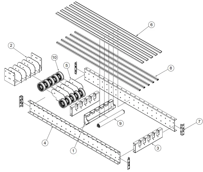
• Model ProSort MRT Parts Drawing and Parts List
| Ref No. | Part No. | Description |
| 1 2 3 | B-11302 049.110 069.7265 | Mounting Angle for Filter/Regulator #094.194 SPRING LOCK PIN – 5/32 in. DIA. X 7/8 in. LONG Belt – 15/16 in. Wide Aramide Power Transmission Belt |
| 4 5 | 094.1149 094.11496 | Ployurethane Tubing – 3/8 in. OD Black (Specify Length) Ployurethane Tubing – 1/2 in. OD Black (Specify Length) |
| 6 7 8 9 10 | 094.14045 094.14089 094.1465 094.1484 094.1485 | Brass Connector Straight Male – 1/2 in. Npt – 1/2 in. Plastic Brass Union Tee – 1/2 in. Plastic -1/2 in. Plastic Plug-in Reducer – 3/8 in. Plastic – 1/2 in. Push-in Plastic Plug – 1/4 in. OD Push-in Type Plastic Plug – 3/8 in. OD Push-in Type |
| 11 | 094.190 | Air Line Filter/Regulator W/Bracket – 1/2 in. Npt |
| 12 13 | 094.1903 094.1912 | 1/2 in. Spacer for Airline Components Air Line Pressure Switch – 24 VDC, Normal Open |
| 14 | 094.194 | Air Line Filter/Regulator W/Bracket |
| 15 | 910.0004 | Manifold – 3/8 in. Inlet, 1/4 in Outlet |
| 16 17 — — 18 — | 923.0064 — B-00913 B-02112 — B-00914 | Lock Out Tag MS Pivot Plate – 1-1/2 in. Flange 3-11/16 in. High 1-9/16 in. High Floor Support Frame 6 in. High (Specify OAW) |
| — — — — — | B-12777 B-12778 B-00915 B-00916 B-00917 | 7 in. High (Specify OAW) 8 in. High (Specify OAW) 9 in. High (Specify OAW) 11-1/2 in. High (Specify OAW) 14-1/2 in. High (Specify OAW) |
| — — — — — | B-02098 B-00919 B-00921 B-00923 B-00925 | 18-1/2 in. High (Specify OAW) 22-1/2 in. High (Specify OAW) 32-1/2 in. High (Specify OAW) 44-1/2 in. High (Specify OAW) 56-1/2 in. High (Specify OAW) |
| — — — 19 | B-02107 B-02109 B-02111 B-00911 | 68-1/2 in. High (Specify OAW) 78-1/2 in. High (Specify OAW) 90-1/2 in. High (Specify OAW) Adjustable Foot Assembly (Specify Length) |
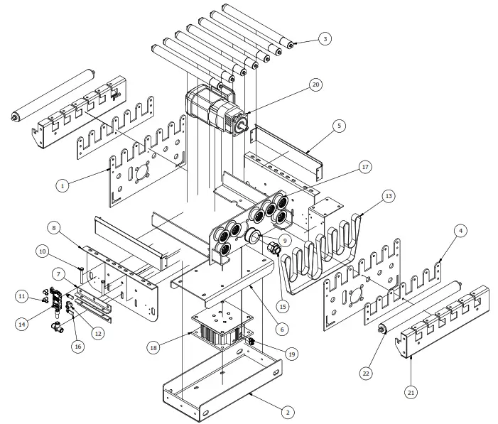
• Model ProSort MRT Drive Parts Drawing and Parts List
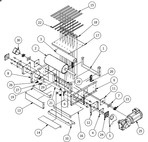
| REF NO. | PART NO. | DESCRIPTION |
| 1 | WA-036553 | BED SPACER CHANNEL WELDMENT (SPECIFY BR) |
| 2 3 | SA-038509 WA-025843 | 8 in. DIA. DRIVE PULLEY ASSEMBLY (SPECIFY BR) 4 in. DIA. PULLEY ASSEMBLY (SPECIFY BR) |
| 4 5 | PT-001465 — | BEARING SPACER – 4 BOLT TORQUE ARM |
| — | PT-083789-R | TORQUE ARM – RIGHT HAND |
| — | PT-083789-L | TORQUE ARM – LEFT HAND |
| 6 | 090.262 | POP-OUT ROLLER BRACKET |
| 7 | PT-085857 | BEARING SPACER – 2 BOLT |
| 8 | PT-126301-R | DRIVE SIDE CHANNEL – RIGHT HAND |
| 9 | PT-126301-L | DRIVE SIDE CHANNEL – LEFT HAND |
| 10 | PT-087065 | TORQUE ARM CHANNEL (SPECIFY BR) |
| 11 | PT-087195 | PULLEY MOUNTING PLATE |
| 12 | PT-087197 | BEARING SUPPORT PLATE |
| 13 | PT-126305 | END GUARD CHANNEL (SPECIFY BR) |
| 14 | PT-126308 | BELT GUARD (SPECIFY BR) |
| 15 | PT-126309 | BELT GUIDE WEARSTRIP |
| 16 | PT-126307 | BOTTOM GUARD (SPECIFY BR) |
| 17 | PT-126306 | WEARSTRIP SUPPORT CHANNEL (SPECIFY BR) |
| 18 | PT-127186 | UNIVERSAL GUIDE RAIL |
| 19 | PT-126300 | POP-OUT ROLLER BRACKET (SPECIFY BR) |
| 20 | B-03191 | BUTT COUPLING ANGLE |
| 21 | B-20760 | PRECISION ROLLER (SPECIFY BR) |
| 22 | B-18590-166 | GUIDE RAIL EXTRUSION |
| 23 | 010.0021 | 2-BOLT FLANGE BEARING – 1 in. BORE |
| 24 | 010.203 | 4-BOLT FLANGE BEARING – 1-7/16 in. BORE |
| 25 | — | GEARMOTOR |
| 26 | 024.14375 | DIVERTER WHEEL |
| 27 | 024.14376 | DIVERTER WHEEL COVER |
| 28 | PT-126304 | BELT TRAN ANGLE (SPECIFY BR) |
| 29 | B-25712-004 | 1-3/8 in. GALV ROLLER |
| 30 | PT-089907 | ENCODER COVER |
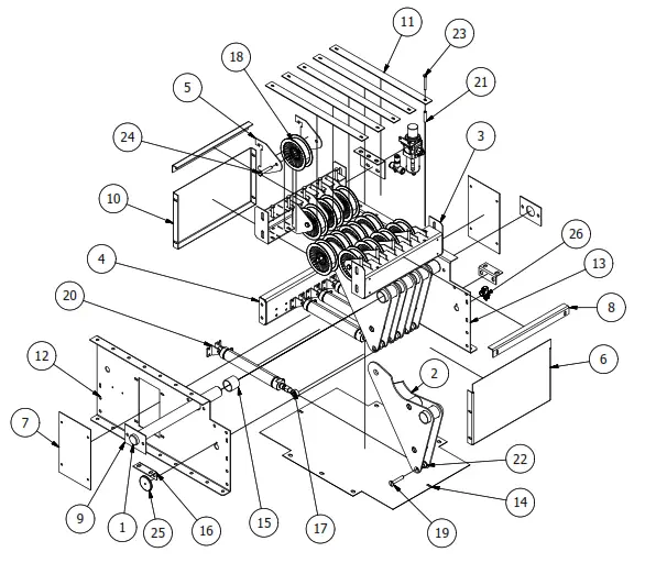
• Model ProSort MRT Pneumatic Take-Up Parts Drawing and Parts List
Use code HYPMANUAL for free shipping on your first order at HytrolParts.com
| REF NO. | PART NO. | DESCRIPTION |
| 1 | WA-009141 | PIVOT SHAFT WELDMENT (SPECIFY BR x 8) |
| 2 | WA-025823 | PIVOT TAKE-UP WELDMENT |
| 3 | WA-025824 | IDLER SUPPORT CHANNEL WELDMENT (SPECIFY BR) |
| 4 | WA-025833 | CYLINDER MOUNTING CHANNEL WELDMENT (SPECIFY BR) |
| 5 | PT-032409 | IDLER PLATE |
| 6 | — | SIDE GUARD “TALL” |
| — | PT-032637 | FOR PNEUMATIC TAKE-UP (SPECIFY BR x 8) |
| — | PT-088414 | FOR PNEUMATIC TAKE-UP “DRIVE END” (SPECIFY BR) |
| 7 | PT-032639 | COVER PLATE |
| 8 | PT-032715 | IDLER LOCKING ANGLE (SPECIFY BR x 8) |
| 9 | PT-032805 | PIVOT SHAFT PLATE |
| 10 | PT-076346 | SIDE GUARD “SHORT” (SPECIFY BR x 8) |
| 11 | PT-080115 | IDLER GUARD 18-1/2 in. LONG |
| 12 | — | SIDE CHANNEL RIGHT HAND |
| — | PT-087018-R | FOR PNEUMATIC TAKE-UP |
| — | PT-088416-R | FOR PNEUMATIC TAKE-UP “DRIVE END” |
| 13 | — | SIDE CHANNEL LEFT HAND |
| — | PT-087018-L | FOR PNEUMATIC TAKE-UP |
| — | PT-088416-L | FOR PNEUMATIC TAKE-UP “DRIVE END” |
| 14 | PT-088226 | BOTTOM GUARD (SPECIFY BR) |
| 15 | B-09226-017 | 1.7 in. OD HR TUBE – 2-1/8 BR |
| 16 | PT-088406 | SUPPORT ANGLE |
| 17 | 019.224 | FEMALE ROD END – 7/16 – 20 RH THREADS |
| 18 | 024.156 | FLAT BELT IDLER – 4 in. DIA. X 1 in. WIDE x 3/8 in. BORE |
| 19 | 042.2044 | 3/8-16 x 2-1/4 in. LONG FLAT HEAD BOLT |
| 20 | 094.121508 | AIR CYLINDER – 8 in. STROKE x 1-1/2 in. BORE |
| 21 | 098.1064 | ALUMINUM SPACER – 1-5/8 in. LONG |
| 22 | 098.150 | SPACER – .406 In. ID x .750 in. OD x .375 in. LONG |
| 23 | 040.1041 | 1/4-20 x 2-1/4 in. LONG HEX HEAD CAP SCREW |
| 24 | 040.306 | 3/8-16 x 2 in. LONG HEX HEAD CAP SCREW |
| 25 | 032.218 | REFLECTOR |
| 26 | 941.650201 | PHOTO EYE |
• Model ProSort MRT Section Parts Drawing and Parts List
| REF NO. | PART NO. | DESCRIPTION |
| 1 | WA-025804 | Brace Channel Weldment (Specify BR x 8) |
| 2 | WA-025834 | Tail Idler Weldment (Specify BR x 8) |
| 3 | WA-025999 | Brace Channel Weldment “Discharge End” (Specify BR x 8) |
| 4 | PT-087011 | Side Channel – 6-1/2 in. High (Specify Length) |
| 5 | PT-087223 | Belt Guard |
| 6 | PT-088292 | Belt Guide Wearstrip – Inter/Tail Section (Specify Length) |
| 7 | B-03191 | Butt Coupling Angle |
| 8 | B-18590 | Guide Rail Extrusion – Inter/Tail Section (Specify Length) |
| 9 | B-20760 | 1.9 in. OD Galv Return Roller – ABEC-1 (Specify BR -1-1/4 x 8) |
| 10 | 024.157 | Flat Belt Idler 4 in. Dia. X 1-1/4 in. Wide x 3/4 in. Bore |
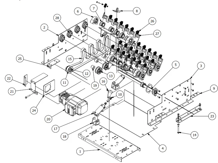
Model ProSort MRT 90° Transfer Parts Drawing and Parts List
| REF NO. | PART NO. | DESCRIPTION |
| 1 | WA-025802 | ROLLER FRAME WELDMENT (SPECIFY BR) |
| 2 | WA-025817 | BASE CHANNEL WELDMENT (SPECIFY BR) |
| 3 | SA-036881-137 | VULCANIZED 138 ROLLER ASSEMBLY – 17- 1/8 in. BR |
| 4 | PT-086781 | SPACER PLATE (SPECIFY BR) |
| 5 | PT-086812 | TRANSFER ROLLER GUARD – 17 in. LONG |
| 6 | PT-086818 | TRANSFER CROSS CHANNEL (SPECIFY BR) |
| 7 | PT-086833 | CROSS ANGLE – 8- 1/2 in. LONG |
| 8 | PT-087017 | SIDE CHANNEL – 18 in. LONG |
| 9 | 024.15502 | FLAT BELT DRIVE WHEEL |
| 10 | 040.309 | 3/8 -16 x 3 in. LONG HEX BOLT-FULLY THREADED |
| 11 | 094.1406 | PLASTIC ELBOW – MALE, 360 DEG. SWIVEL 1/4 in. TO 1/8 in. NPTF |
| 12 | 094.14079 | PLASTIC ELBOW – MALE, 360 DEG. SWIVEL 3/8 in. TO 1/8 in. NPTF |
| 13 | — | FLEXPROOF ENDLESS BELT – 1 in. WIDE |
| — | 069.72215 | 15 in. BR |
| — | 069.72218 | 18 in. BR |
| — | 069.72221 | 21 in. BR |
| — | 069.72224 | 24 in. BR |
| — | 069.72227 | 27 in. BR |
| 14 | 094.10795 | 4-WAY SINGLE SOLENOID AIR VALVE |
| 15 | 099.128420 | KEYLESS BUSHING – 20mm ID x 45mm OD |
| 16 | 923.0059 | MUFFLER – 1/8 in. NPT |
| 17 | 923.00975 | FLAT BELT IDLER – 2- 3/4 in. DIA. X 1.4 in. WIDE |
| 18 | 923.01022 | GUIDE TABLE – 100mm BORE, 20mm STROKE |
| 19 | 923.0104 | UNFIT FITTING – 1/4 in. TUBE – 1/4 in. PORTS |
| 20 | 300.0322 | GEARMOTOR – 1/2 hp, 230/460/3, 462 rpm |
| 21 | WA-025804 | NOTCHED BRACE CHANNEL WELDMENT (SPECIFY BR) |
| 22 | B-20760 | GALVANIZED ROLLER ASSEMBLY – 1.9 in. OD (SPECIFY BR) |
• Model ProSort MRT 30° Transfer Parts Drawing and Parts List
| REF NO. | PARTS NO. | DESCRIPTION |
| 1 | PT-112594 | CYLINDER SUPPORT CHANNEL (SPECIFY BR) |
| 2 | — | DIVERTER SUPPORT ANGLE |
| — | PT-118430-R | DIVERTER SUPPORT ANGLE – RH, 15 in. BR |
| — | PT-112587-R | DIVERTER SUPPORT ANGLE – RH, 18-27 in. BR |
| 3 | — | DIVERTER SUPPORT ANGLE |
| — | PT-118430-L | DIVERTER SUPPORT ANGLE – LH, 15 in. BR |
| — | PT-112587-L | DIVERTER SUPPORT ANGLE – LH, 18-27 in. BR |
| 4 | PT-112611 | BOTTOM GUARD (SPECIFY BR) |
| 5 | B-17611 | DRIVE SHAFT – FULL KEYWAY (SPECIFY BR) |
| 6 | 010.351 | TAPPED BASE PILLOW BLOCK |
| 7 | 094.4101 | DRIVE SPOOL – 2 in. DIA. |
| 8 | PT-112263 | SPARE O-RING HOLDER |
| 9 | PT-112634 | DIVERTER ATTACHMENT ANGLE |
| 10 | 019.224 | FEMALE ROD END – 7/16 – 20 RH THREADS |
| 11 | 024.15502 | FLAT 1 in. BELT DRIVE WHEEL – 2-1/2 in. DIA. |
| 12 | 099.128420 | KEYLESS BUSHING – 20mm ID x 45mm OD |
| 13 | 024.158 | FLAT BELT IDLER – 2-3/4 in. DIA. X 1.15 in. WIDTH |
| 14 | 040.309 | 3/8-16 x 3 in. LONG HEX BOLT – FULL THREAD |
| 15 | 069.72487 | FLEXPROOF ENDLESS BELT – 3/16 in. WIDTH x 86 in. LENGTH |
| 16 | PT-111452 | DIVERTER PIVOT ANGLE – 30 DEGREE |
| 17 | 094.10652 | AIR CYLINDER – 2 in. STROKE, 40mm BORE |
| 18 | 094.106521 | TRUNNION BRACKET FOR AIR CYLINDER 40mm |
| 19 | 098.1675 | SPACER – 0.515 in. ID x 1.25 in. OD x 1 in. LENGTH |
| 20 | 300.03225 | GEARMOTOR – 1/2 hp, 230/460/3, 462 rpm |
| 21 | PT-111510 | SIDE GUARD |
| 22 | PT-111852 | END GUARD |
| 23 | PT-112499 | DIVERTER TAKE-UP ANGLE |
| 24 | — | MOTOR SUPPORT ANGLE |
| — | PT-112586-R | MOTOR SUPPORT ANGLE – RH |
| — | PT-112586-L | MOTOR SUPPORT ANGLE – LH (SHOWN) |
| 25 | PT-112633 | BELT TAKE-UP ANGLE |
| 26 | 024.14375 | DIVERTER WHEEL 1.75in. DIA. |
| 27 | PT-106162 | DIVERT WHEEL SUPPORT ANGLE |
| 28 | 010.0021 | 2-BOLT FLANGE BEARING – 1 in. BORE |
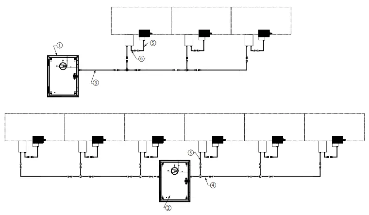
• HyPower Cabling Parts List and Drawing
| REF NO. | PART NO. | DESCRIPTION |
| 1 | EB-000001 | Single-Sided Disconnect Box |
| 2 | EB-000002 | Double-Sided Disconnect Box |
| 3 | — | Double-Ended HyPower Extension Cable |
| — | 941.430301 | Double-Ended HyPower Extension Cable – 1 Meter |
| — | 941.430302 | Double-Ended HyPower Extension Cable – 2 Meter |
| — | 941.430303 | Double-Ended HyPower Extension Cable – 3 Meter |
| — | 941.430306 | Double-Ended HyPower Extension Cable – 6 Meter |
| 4 | 941.430200 | HyPower T-Connector |
| 5 | 941.430101 | Male Single-Ended HyPower Cable |
| 6 | 941.430001 | Female Single-Ended HyPower Cable |
Use code HYPMANUAL for free shipping on your first order at HytrolParts.com
[email protected] | www.HytrolParts.com
“Building Relationships One Conveyor Part at a Time”
Use code HYPMANUAL for free shipping on your first order at HytrolParts.com


