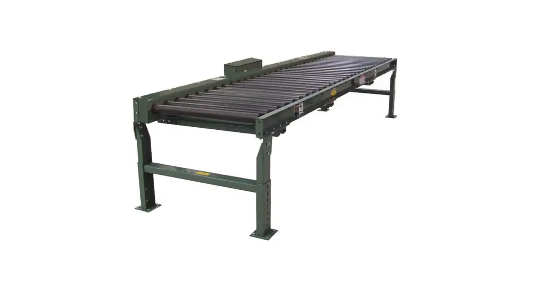
![]() 190LR Belt Driven Live Roller Conveyor
190LR Belt Driven Live Roller Conveyor
Instruction Manual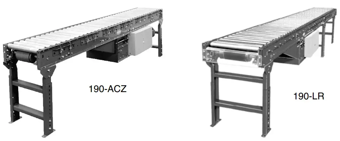
190LR Belt Driven Live Roller Conveyor
Use code HYPMANUAL for free shipping on your first order at HytrolParts.com
WARNING
Do not start conveyor until personnel are clear.
- Warning Signs
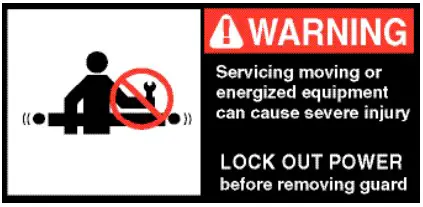
In an effort to reduce the possibility of injury to personnel working around HYTROL conveying equipment, warning signs are placed at various points on the equipment to alert them of potential dangers. Please check equipment and note all warning signs. Make certain your personnel are alerted to and obey these warnings. Shown below are typical signs that are attached to this equipment.
 PLACED NEXT TO DRIVE, BOTH SIDES. COLOCADA JUNTO A LA UNIDAD MOTRIZ, EN AMBOS LADOS.
 PLACED ON 20 FT. INTERVALS,BOTH SIDES. COLOCADA EN INTERVALOS DE 20 PIES, A AMBOS LADOS.
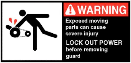 PLACED ON ALL CHAIN GUARDS. COLOCADA EN TODAS LAS GUARDA CADENAS.
 PLACED ON TERMINATING ENDS. COLOCADA EN LOS EXTREMOS.
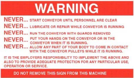 PLACED AT DRIVE OF ALL POWERED CONVEYORS. COLOCADA EN LA UNIDAD MOTRIZ DE TODOS LOS TRANSPORTADORES MOTORIZADOS.
 PLACED WHERE POP-OUT ROLLERS ARE USED COLOCADAS DONDE LOS RODILLOS DE SALI DA FACIL SON UTILIZADOS
NOTE: BILINGUAL (SPANISH) LABELS AVAILABLE UPON REQUEST.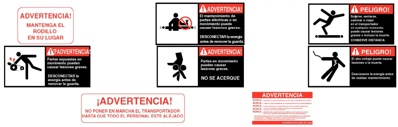
INTRODUCTION
This manual provides guidelines and procedures for installing, operating, and maintaining your conveyor. A complete parts list is provided with recommended spare parts highlighted in gray. Important safety information is also provided throughout the manual.
For safety to personnel and for proper operation of your conveyor, it is recommended that you read and follow the instructions provided in this manual.
● Receiving and Uncrating
- Check the number of items received against the bill of lading.
- Examine condition of equipment to determine if any damage occurred during shipment.
- Move all crates to area of installation.
- Remove crating and check for optional equipment that may be fastened to the conveyor. Make sure these parts (or any foreign pieces) are removed.
NOTE: If damage has occurred or freight is missing, see the “Important Notice” attached to the crate.
INSTALLATION
● Installation Safety Precautions for Conveyors and Related Equipment
GUARDS AND GUARDING
Interfacing of Equipment. When two or more pieces of equipment are interfaced, special attention shall be given to the interfaced area to insure the presence of adequate guarding and safety devices. Guarding Exceptions. Wherever conditions prevail that would require guarding under these standards, but such guarding would render the conveyor unusable, prominent warning means shall be provided in the area or on the equipment in lieu of guarding. Guarded by Location or Position. Where necessary for the protection of employees from hazards, all exposed moving machinery parts that present a hazard to employees at their work station shall be mechanically or electrically guarded, or guarded by location or position. When a conveyor passes over a walkway, roadway, or work station, it is considered guarded solely by location or position if all moving parts are at least 8 ft. (2.44 m) above the floor or walking surface or are otherwise located so that the employee cannot inadvertently come in contact with hazardous moving parts. Although overhead conveyors may be guarded by location, spill guard, pan guards, or equivalent shall be provided if the product may fall off the conveyor for any reason and if personnel would be endangered.
HEADROOM
When conveyors are installed above exit passageways, aisles, or corridors, there shall be provided a minimum clearance of 6 ft. 8 in. (2.032 m) measured vertically from the floor or walking surface to the lowest part of the conveyor or guards. Where system function will be impaired by providing the minimum clearance of 6 ft. 8 in. (2.032 m) through an emergency exit, alternate passageways shall be provided. It is permissible to allow passage under conveyors with less than 6 ft. 8 in. (2.032 m) clearance from the floor for other than emergency exits if a suitable warning indicates low headroom.
● Support Installation
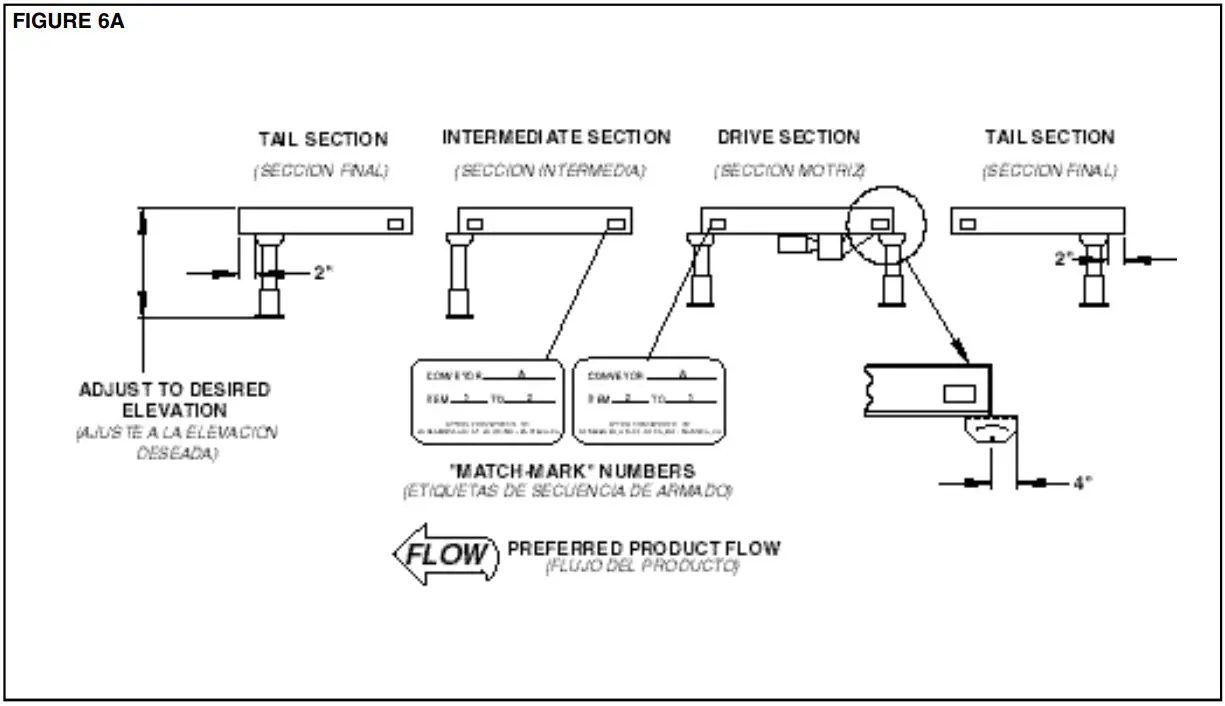
- Determine primary direction of product flow. Figure 5A indicates the preferred flow as related to the drive.
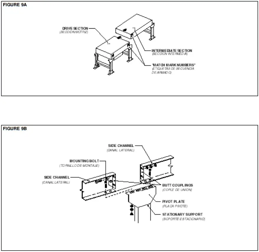
- Refer to “Match-Mark” numbers on ends of conveyor sections. (Figure 6A).
- Attach supports to both ends of drive section and to one end of intermediate or tail sections (Figure 6A). Hand tighten bolts only at this time.
- Adjust elevation to required height.

● Ceiling Hanger Installation
If conveyors are to be used in an overhead application, ceiling hangers may have been supplied in place of floor supports.
Figure 7A shows how a ceiling hanger mounts to a conveyor section. Ceiling hangers should be mounted at section joints. For safety information concerning conveyors mounted overhead, refer to “Installation Safety Precautions” on Page 5.
NOTE: When installing ceiling hanger rods in an existing building, all methods of attachment must comply with local building codes.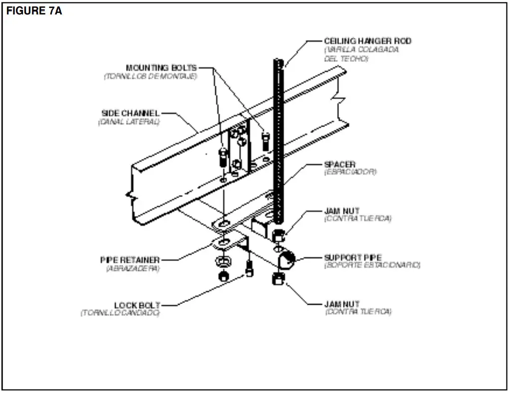 ● Conveyor Set-Up
- Mark a chalk line on floor to locate center of the conveyor.
- Place the drive section in position.
- Install remaining sections placing end without support on extend support of previous section (Figure 6A and 9A). Check “Match Mark” Numbers to see that adjoining sections are in proper sequence
- Fasten sections together with butt couplings and pivot plates (Figure 9B). Hand tighten bolts only at this time.
- Insure that conveyor is level across width and length of unit. Adjust supports as necessary.
- Insure that all bed sections are square. Refer to Page 20 for Instructions on How To Square The Beds.
- Tighten all butt coupling and support mounting bolts and lag conveyor to floor.
- Install electrical controls and wire motor. See Page 10.
- Install and track belt per instructions on Page 18.
- Install tread rollers (See Page 23)
 ● Electrical Equipment
WARNING!
Electrical controls shall be installed and wired by a qualified electrician. Wiring information for the motor and controls are furnished by the equipment manufacturer.
CONTROLS
Electrical Code: All motor controls and wiring shall conform to the National Electrical Code (Article 670 or other applicable articles) as published by the National Fire Protection Association and as approved by the American Standards Institute, Inc.
CONTROL STATIONS
A) Control stations should be so arranged and located that the operation of the equipment is visible from them, and shall be clearly marked or labeled to indicate the function
controlled.
B) A conveyor which would cause injury when started shall not be started until employees in the area are alerted by a signal or by a designated person that the conveyor is about to start.
When a conveyor would cause injury when started and is automatically controlled or must be controlled from a remote location, an audible device shall be provided which can be clearly heard at all points along the conveyor where personnel may be present. The warning device shall be actuated by the controller device starting the conveyor and shall continue for a required period of time before the conveyor starts. A flashing light or similar visual warning may be used in conjunction with or in place of the audible device if more effective in particular circumstances. Where system function would be seriously hindered or adversely affected by the required time delay or where the intent of the warning may be misinterpreted (i.e., a work area with many different conveyors and allied devices), clear, concise, and legible warning shall be provided. The warning shall indicate that conveyors and allied equipment may be started at any time, that danger exists, and that personnel must keep clear. The warnings shall be provided along the conveyor at areas not guarded by position or location.
C) Remotely and automatically controlled conveyors, and conveyors where operator stations are not manned or are beyond voice and visual contact from drive areas, loading areas, transfer points, and other potentially hazardous locations on the conveyor path not guarded by location, position, or guards, shall be furnished with emergency stop buttons, pull cords, limit switches, or similar emergency stop devices.
All such emergency stop devices shall be easily identifiable in the immediate vicinity of such locations unless guarded by location, position, or guards. Where the design, function, and operation of such conveyor clearly is not hazardous to personnel, an emergency stop device is not required. The emergency stop device shall act directly on the control of the conveyor concerned and shall not depend on the stopping of any other equipment. The emergency stop devices shall be installed so that they cannot be overridden from other locations.
D) Inactive and unused actuators, controllers, and wiring should be removed from control stations and panel boards, together with obsolete diagrams, indicators, control labels, and other material which serve to confuse the operator.
SAFETY DEVICES
A) All safety devices, including wiring of electrical safety devices, shall be arranged to operate in a “Fail-Safe” manner, that is, if power failure or failure of the device itself would occur, a hazardous condition must not result.
B) Emergency Stops and Restarts. Conveyor controls shall be so arranged that, in case of emergency stop, manual reset or start at the location where the emergency stop was initiated, shall be required of the conveyor(s) and associated equipment to resume operation.
C) Before restarting a conveyor which has been stopped because of an emergency, an inspection of the conveyor shall be made and the cause of the stoppage determined. The starting device shall be locked out before any attempt is made to remove the cause of stoppage, unless operation is necessary to determine the cause or to safely remove the stoppage.
Refer to ANSI Z244.1-1982, American National Standard for Personnel Protection – Lockout/Tagout of Energy Sources – Minimum Safety Requirements and OSHA Stan dard Number 29 CFR 1910.147 “The Control of Hazardous Energy (Lockout/Tagout).”
OPERATION
● Operation Safety Precautions
A) Only trained employees shall be permitted to operate conveyors. Training shall include instruction in operation under normal conditions and emergency situations.
B) Where employee safety is dependent upon stopping and/or starting devices, they shall be kept free of obstructions to permit ready access.
C) The area around loading and unloading points shall be kept clear of obstructions which could endanger personnel.
D) No person shall ride the load-carrying element of a con- veyor under any circumstances unless that person is specifically authorized by the owner or employer to do so. Under those circumstances, such employee shall only ride a conveyor which incorporates within its supporting structure, platforms or control stations specifically designed for carrying personnel. Under no circumstances shall any person ride on any element of a vertical conveyor. Owners of conveyors should affix warning devices to the conveyor reading Do Not Ride Conveyor.
E) Personnel working on or near a conveyor shall be instructed as to the location and operation of pertinent stopping devices.
F) A conveyor shall be used to transport only material it is capable of handling safely.
G) Under no circumstances shall the safety characteristics of the conveyor be altered if such alterations would endanger personnel.
H) Routine inspections and preventive and corrective maintenance programs shall be conducted to insure that all safety features and devices are retained and function properly.
I) Personnel should be alerted to the potential hazard of entanglement in conveyors caused by items such as long hair, loose clothing, and jewelry.
J) As a general rule, conveyors should not be cleaned while in operation. Where proper cleaning requires the conveyor to be in motion and a hazard exists, personnel should be made aware of the associated hazard.
● Conveyor Start-Up
Before conveyor is turned on, check for foreign objects that may have been left inside conveyor during installation.
These objects could cause serious damage during start-up. After conveyor has been turned on and is operating, check motors, reducers, and moving parts to make sure they are working freely.
CAUTION!
Because of the many moving parts on the conveyor, all personnel in the area of the conveyor need to be warned that the conveyor is about to be started.
MAINTENANCE
● Maintenance Safety Precautions
A ) Maintenance, such as lubrication and adjustments, shall be performed only by qualified and trained personnel.
B ) It is Important that a maintenance program be established to insure that all conveyor components are maintained in a condition which does not constitute a hazard to personnel.
C ) When a conveyor is stopped for maintenance purposes, starting devices or powered accessories shall be locked or tagged out in accordance with a formalized procedure
designed to protect all person or groups involved with the conveyor against an unexpected start.
D ) Replace all safety devices and guards before starting equipment for normal operation.
E ) Whenever practical, DO NOT lubricate conveyors while they are in motion. Only trained personnel who are aware of the hazard of the conveyor in motion shall be allowed to lubricin ate
SAFETY GUARDS
Maintain all guards and safety devices IN POSITION and IN SAFE REPAIR .
WARNING SIGNS
Maintain all warning signs in a legible condition and obey all warnings. See Page 3 of this manual for examples of warning signs.
● Lubrication
The drive chain is pre-lubricated from the manufacturer by a hot dipping process that ensures total lubrication of all components. However, continued proper lubrication will greatly extend the useful life of every drive chain.
Drive Chain lubrication serves several purposes including:
- Protecting against wear of the pin-bushing joint
- Lubricating chain-sprocket contact surfaces
- Preventing rust or corrosion
For normal operating environments, lubricate every 2080 hours of operation or every 6 months, whichever comes first. Lubricate with a good grade of non-detergent petroleum or synthetic lubricant (i.e., Mobile 1 Synthetic). For best results, always use a brush to generously lubricate the chain. The proper viscosity of lubricant greatly affects its ability to flow into the internal areas of the chain. Refer to the table below for the proper viscosity of lubricant for your application.
| Ambient Temperature Degrees F | SAE | ISO |
| 20-40 | 20 | 46 or 68 |
| 40-100 | 30 | 100 |
| 100-120 | 40 | 150 |
The drive chain’s lubrication requirement is greatly affected by the operating conditions. For harsh conditions such as damp environments, dusty environments, excessive speeds, or elevated temperatures, it is best to lubricate more frequently. It may be best, under these conditions, to develop a custom lubrication schedule for your specific application. A custom lubrication schedule may be developed by inspecting the drive chain on regular time intervals for sufficient lubrication. Once the time interval is determined at which the chain is not sufficiently lubricated, lubricate it and schedule the future lubrication intervals accordingly.
● Racked Sections
It is important that each bed section be checked for an outofsquare condition. If conveyor is not square, tracking problems will result. Figure 17A indicates a racked section.
TO CORRECT AN OUT-OF-SQUARE SECTION
- Locate points on corners of section and measure distance “A” & “B”. If the dimensions are not equal, the section will need to be squared. (Figure 17B).
- Use crossbreeding supplied on underside of conveyor to square each section. Adjust turnbuckle until Dimensions “A” & “B” are equal.
- After all bed sections have been checked and corrected for “racked condition”, tighten all butt couplings and pivot plate bolts.
- Make final check to see that all conveyor sections are level across width and length. If entire conveyor is level, supports can be lagged to floor.
IMPORTANT!
Being out of level width of conveyor can cause package drift on long conveyor lines.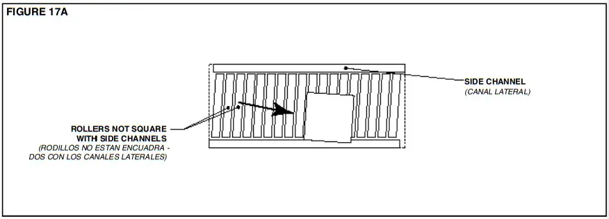 “Racked” conveyor sections will cause package to travel toward side of conveyor.
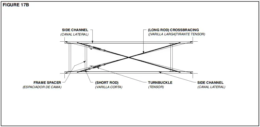 ● Belt Installation
INSTALLING THE BELT
The conveyor drive belt has been pre-cut and the proper lacing attached at the factory. Before attempting to install the belt, its top and bottom sides must be determined. One side of the belt has a “Friction Surface” and the other has a “PVC Embossed Cover”. The belt should be installed with the Embossed Cover side up on the Model LR and with the Friction Surface side up on the Model ACZ. The bottom side of the belt will be marked “THIS SIDE DOWN”. Thread belt through conveyor. (Figure 19B). Pull belt ends together and insert lacing pin. (Figure 19A).
NOTE: If belt ends cannot be pulled together by hand, it may be necessary to loosen take-ups (at tail pulley, etc.), minimum position or use a belt puller so lacing pin can be easily inserted.
BELT TENSION
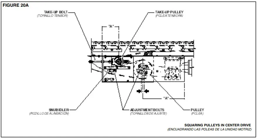
For maximum efficiency, maintain enough belt tension so drive pulley will not slip when carrying the rated load. Belt tension should first be adjusted with the take-up pulley or tail pulley. (Figure 19B).
Keep pulleys square with bed by moving both take-up bolts and equal amount.
CAUTION!
Excessive slippage will reduce belt life and damage drive pulley lagging. Never apply more tension than is needed.
Over-tension will cause extra wear to belt and bearings and will require extra power from drive.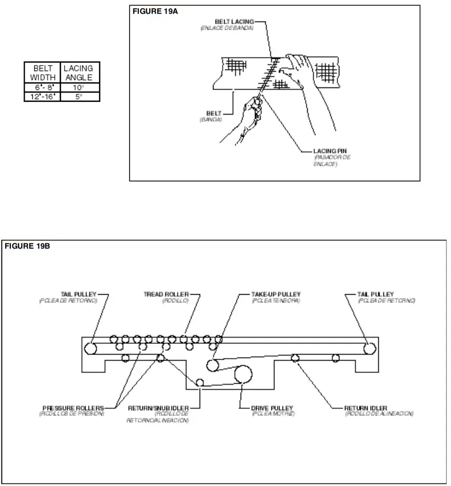 ● Belt Tracking
IMPORTANT: The drive belt should be checked for proper tracking prior to installing tread rollers. This will allow easy access to items that might need adjusting.
PRE-TRACKING INSPECTION
Before attempting to physically track the belt:
- Make sure all bed sections are square. See information on “Racked Sections”, Page 16.
- Make sure conveyor is level across the width and length of unit. Adjust supports as necessary.
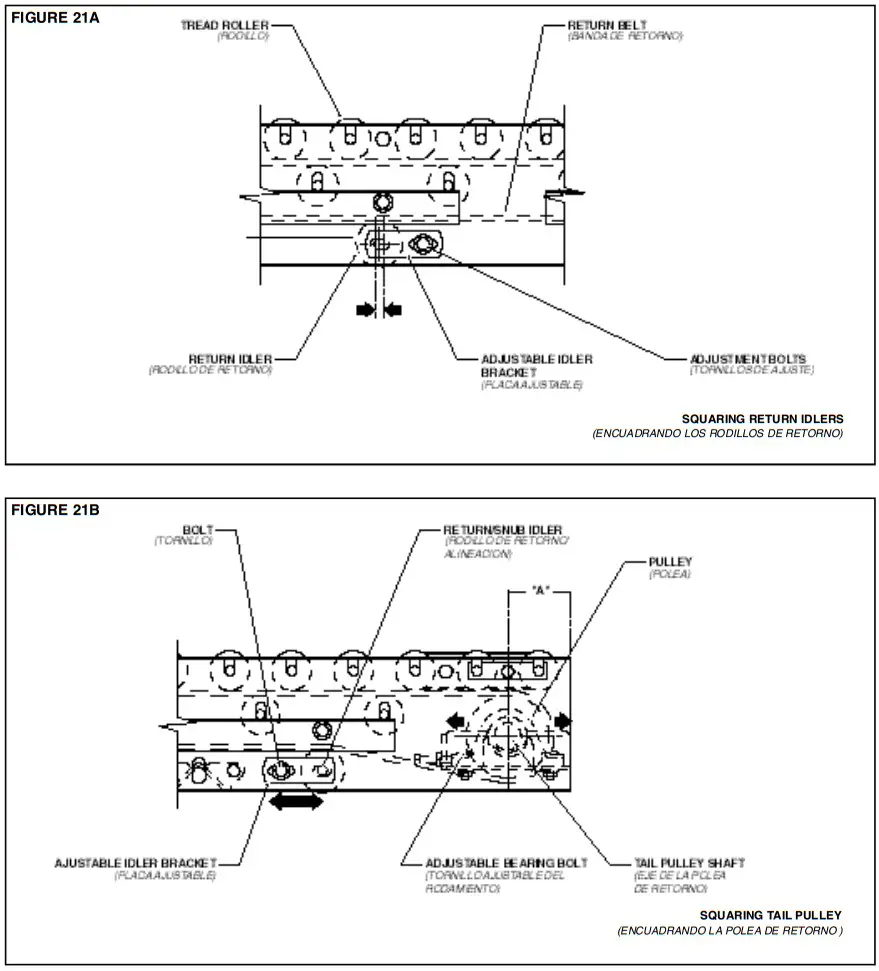
- Make sure all pulleys, return idlers, and snub idlers are square with conveyor bed. (Figures 20A thru 21B). Dimension “A” should be equal on both sides of unit.
- Make sure belt has been properly threaded through conveyor. See “Belt Installation”, Page 18.
 CAUTION!
Only trained personnel should track conveyor belt which must be done while conveyor is in operation.
IMPORTANT: When belt tracking adjustments are made, they should be minor (1/16 in. at a time on idlers, etc., should be sufficient.). Give the belt adequate time to react to the adjustments. It may take several complete revolutions around the conveyor for the belt to begin tracking properly on long, slow conveyor lines. A) Stand at tail pulley looking toward drive and note what direction belt is traveling. B) Having observed belt and determined tracking problem, follow procedures in “How to Steer The Belt”, See Figure 22A.
HOW TO STEER THE BELT
Condition 1. . .When the belt is running in the direction (FLOW) with the arrow, but tracking (drifting) towards Side “X”, move the Snub Idler nearest the INFEED end of Side “Y” towards the DISCHARGE end of the conveyor.
Condition 2. . . When the belt is running in the direction (FLOW) with the arrow, but tracking (drifting) towards Side “Y”, move the Snub Idler nearest the INFEED end of Side “X” towards the DISCHARGE end of the conveyor. If Belt Direction (FLOW) is reversed, all the above conditions will remain the same as in Figure 22A, except you are now viewing the conveyor from the opposite end. If belt continues to track improperly, re-check all items covered in “Pre-Tracking Inspection” and make corrections as necessary.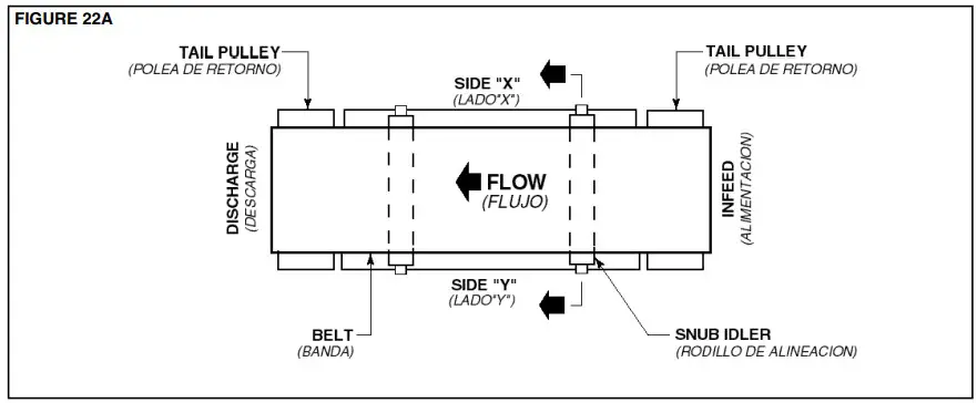 NOTE: In all conditions, you are viewing the Conveyor Belt from the INFEED end. All corrections will be made from the INFEED end of conveyor.
● Tread Roller Installation
The Model “LR” & “ACZ” conveyors are equipped with “pop-out” tread rollers that are removed before installation. After the belt has been installed and tracked properly, the tread rollers must be re-installed.
On all but three rollers at either end of unit, they are simply dropped into the slots in the frame channels.
To drive the end rollers, they are connected with “O”-Rings as shown in Figure 23A. Note that the center roller has two grooves and the others have only one.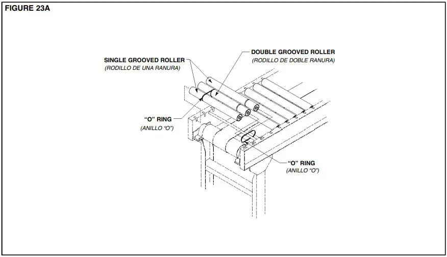 ● Tracking the Package
Unsquared Tread Rollers can cause a package to track improperly. Check to make sure the Tread Rollers are square with the conveyor side channels as shown in Figure 24A.
If the Tread Rollers are not square, refer to the installation segment titled “Racked Sections” on Page 16.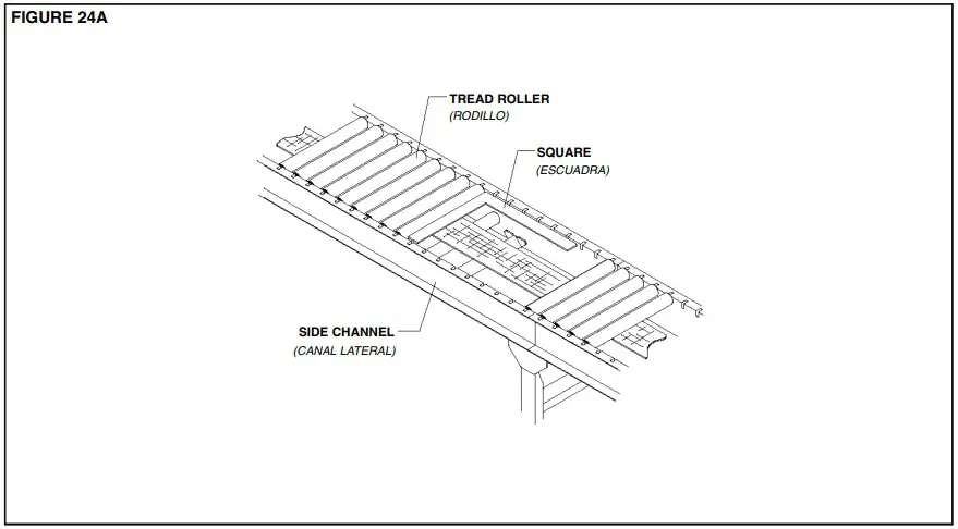 ● Pressure Adjustment
MODEL 190-LR (Figure 27A)
The Model 190-LR is equipped with Pressure Adjustment Angles that support the pressure rollers and hold the drive belt in contact with the tread rollers. To adjust the driving pressure, follow the steps listed below.
- Loosen bolts in Pressure Adjustment Angles.
- Raise Pressure Adjustment Angles, both sides of conveyor, until proper force is obtained to drive the product. Be sure to keep angles as near level as possible.
- Retighten bolts.
NOTE: Over-adjustment will raise tread rollers shafts out of their seat causing them to be unstable.
MODEL 190-ACZ (Figure 27B)
The Model 190-ACZ is similar to the LR, except the suspension angles are spring-loaded. Knurled nuts allow the conveyor to be finely adjusted for minimum pressure accumulation.
To make this adjustment, follow the steps listed below.
- With conveyor running, reduce pressure on all tread rollers to zero by loosening the knurled adjustment nuts (both sides of conveyor).
- Place heaviest item to be conveyed on infeed end of conveyor. Increase pressure under the item by tightening the knurled nuts. Apply only enough pressure to barely move the item.
- As the item moves, continue adjustment ahead of item until it moves the entire length of conveyor.
- Return item to infeed end of unit. It should now travel the entire length of conveyor. If not, repeat the adjustment procedure in the problem area.
NOTE: Do not apply more pressure than necessary to move the heaviest package.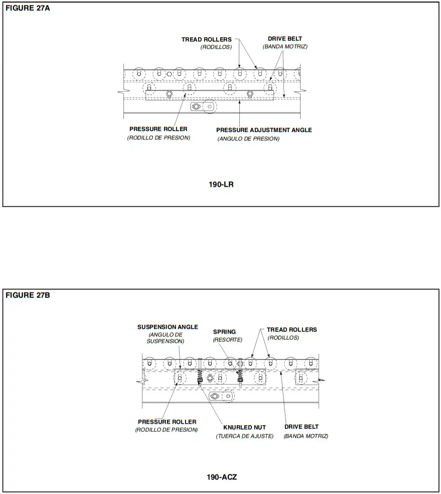 ● Drive Chain Alignment and Tension
The drive chain and sprockets should be checked periodically for proper tension and alignment. Improper adjustment will cause extensive wear to the drive components.
TO MAKE ADJUSTMENTS
- Remove chain guard.
- Check sprocket alignment by placing a straightedge across the face of both sprockets (Figure 29A). Loosen set screws and adjust as needed. Re-tighten set screws.
- To adjust chain tension, loosen bolts that fasten motor base to mounting angles, both sides of the conveyor.
- Tighten take-up bolts until desired chain tension is reached. (Figures 29B & 29C). Re-tighten mounting bolts.
- Lubricate chain per lubrication instructions.
- Replace chain guard so that it does not interfere with drive.
CAUTION!
Never remove chain guards while the conveyor is running. Always replace guards after adjustments are made.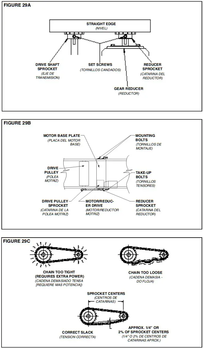
Trouble Shooting
The following charts list possible problems that may occur in the operation of the conveyor.
TROUBLE SHOOTING DRIVES
| TROUBLE | CAUSE | SOLUTION |
| Conveyor will not start or motor quits frequently. | 1)Motor is overloaded 2)Motor is drawing too much current. | 1)Check for overloading of conveyor. 2)Check heater or circuit breaker and change if necessary. |
| Drive chain and sprockets wear excessively. | 1)Lack of lubrication on chain causing chain stretch which creates improper chain to sprocket mesh. 2)Sprockets are out of alignment. 3)Loose chain. | 1)Replace chain and sprockets. Provide adequate lubrication. NOTE: If problem reoccurs, a chain take-up may be required. 2)Align sprockets. See “Drive Chain Alignment and Tension”. 3)Tighten chain. |
| Loud popping or grinding noise. | 1)Defective bearing. 2)Loose set screws in bearing. 3)Loose drive chain. | 1)Replace bearing. 2)Tighten set screw. 3)Tighten chain. |
| Motor or reducer overheating. | 1)Conveyor is overloaded. 2)Low voltage to motor. 3)Low lubricant level in reducer. | 1)Check capacity of conveyor and reduce load to recommended level. 2)Have electrician check and correct as necessary. 3)Relubrication per manufacturer’s recommendations. For HYTROL reducer, refer to separate manual. |
| Belt does not move, but drive runs. | 1)Conveyor is overloaded. 2)Belt is too loose 3)Lagging on drive pulley is worn. | 1)Reduce load. 2)Use belt take-up to tighten belt. 3)Replace drive pulley lagging and tighten belt. |
| Belt moves, but tread rollers do not. | 1) Not enough pressure between tread rollers and drive belt. | 1) Adjust pressure rollers (See “Pressure Adjustment”). |
TROUBLE SHOOTING DRIVE BELT TRACKING
| TROUBLE | CAUSE | SOLUTION |
| Belt creeps to one side at tail pulley. | 1) Tail pulley, return idler, or snub idler near tail pulley not properly aligned or square with bed. | 1) Adjust as necessary. See “Belt Tracking Pre-Tracking Inspection” in this manual for details. |
| Entire belt creeps to one side. | 1)Conveyor not straight. 2)Conveyor not level. 3)Material build-up on rollers, pulleys, or idlers. | 1)Re-align bed sections as necessary. 2)Correct as necessary. 3)Remove residue and install belt cleaners or scrapers if possible. |
TROUBLE SHOOTING MINIMUM PRESSURE OPERATION—190-ACZ
| TROUBLE | CAUSE | SOLUTION |
| Cartons will not accumulate with minimum pressure. | 1) Spring tension adjusted too lightly. | 1) Adjust knurled nuts on both sides of conveyor to loosen spring tension on rollers. |
| Carton will not move on conveyor. | 1)Not enough tension or pressure on drive belt. 2)Drive belt too loose. | 1)Increase spring tension on pressure rollers. 2)Use belt take-up to tighten belt. |
● Planned Maintenance Checklist
The following is a general maintenance checklist which covers the major components of your conveyor. This will be helpful in establishing a standard maintenance schedule.
| COMPONENT | on wow- nrs5 circler at alit SUGGL ICC Alton | nan SCOOPIECULE | |||
| ” Week | Month | Quality | |||
| Check teepee Sure | |||||
| MOTOR | Check teepee Sure | ||||
| Check Maureen Elul ‘. | |||||
| Check Noise | |||||
| REDUCER | Check Termeretre | ||||
| Check Cil Lecel | |||||
| Check Tension | |||||
| DRIVE CHAIN | LS:ideate | ||||
| Check for ‘Abe | |||||
| SPROCKETS | Check br Wen | ||||
| Check Set Screws &Keys | |||||
| Check Tracking | |||||
| D ELT | Check Tension | ||||
| Check Lade | |||||
| 0 EAR114GS | Check Noise | ||||
| Pulleys & Rolas) | Check MountingRohs | ||||
| Check Torreon | |||||
| V-BELTS | Check for Wear | ||||
| Check S heave Alignment | |||||
| STRUCTURAL | Gergel Check: A.II locate bens. etc. | ||||
NOTE: Check Set Screws after the first 24 Hours of operation.
● How to Order Replacement Parts
Included in this manual are parts drawings with complete replacement parts lists. Minor fasteners, such as nuts and bolts, are not included.
When ordering replacement parts:
- Contact Dealer from whom conveyor was purchased or nearest HYTROL Distributor.
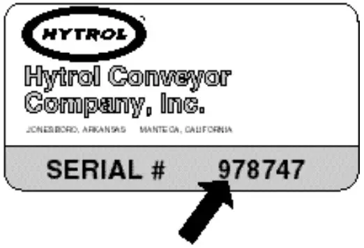
- Give Conveyor Model Number and Serial Number or HYTROL Factory Order Number.
- Give Part Number and complete description from Parts List.
- Give type of drive. Example—8” End Drive, 8” Center Drive, etc.
- If you are in a breakdown situation, tell us. . .
Model 190- LR Parts Drawing 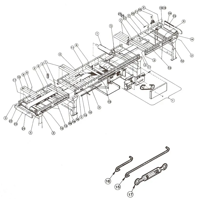 ● Model 190-LR Parts List
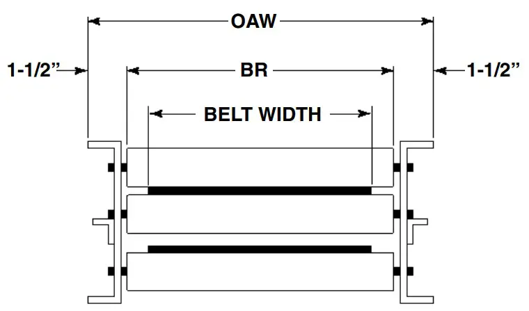 See Page 32 for Information on How To Order Replacement Parts
Recommended Spare Parts Highlighted in Gray
| BR | 13″ | 15″ | 17″ | 19″ | 21″ | 23″ | 25″ | 27″ | 31″ | 33″ | 37″ | 39″ |
| BELT WIDTH | 6″ | 6″ | 8″ | 8″ | 8″ | 12″ | 12″ | 12″ | 16″ | 16″ | 16″ | 16″ |
| OAW | 16″ | 18″ | 20″ | 22″ | 24″ | 26″ | 28″ | 30″ | 34″ | 36″ | 40″ | 42″c |
| Ref. No. | Part No. | Description |
| 1 2 — — — | — — B-05730 B-05731 B-05732 | Drive Assembly (See pages 38 & 39) Frame Channel 4 ft. Long 5 ft. Long 6 ft. Long |
| — — — — 3 | B-05733 B-05734 B-17619 B-05735 B-03191 | 7 ft. 6 in. Long 8 ft. Long 9 ft. Long 10 ft. Long Butt Coupling Plate |
| 5 6 7 8 9 | B-03916 B-05477 B-01982 B-06535 B-21914 | Bed Spacer (Specify BR) Threaded Section Spacer (Specify BR) 1.9 in. Dia. Galvanized Roller (Specify BR) 1.9 in. Dia. Galv. Roller—One Groove (Specify BR) 1.9 in. Dia. Galv. Roller—Two Grooves (Specify BR) |
| 10 11 12 13 — | 090.255 B-03894 B-00944 — B-06771 | 0-Ring 2-1/8 in. Dia. Snub Roller (Specify BR) 7/16 in. Hex Idler Bracket Pressure Adjustment Angle 19 in. Long |
| — — — 14 15 16 17 18 19 | B-03061 5-02616 B-02617 B-05588 044.120 044.121 049.308 B-05740 B-05743 | 25 in. Long 33 in. Long 37 in. Long Roller Bracket-3 in. Roller Centers Cross Brace Rod-70 in. Long Cross Brace Rod-6 in. Long Turnbuckle Take-Up Bracket Assembly—RH Take-Up Bracket Assembly—LH |
| Ref. No. | Part No. | Description |
| 20 21 22 23 24 | 040.305 041.300 010.3011 B-21185 B-09800 | Take-Up Bolt-3/8-16 x 1-1/2 in. Long. Hex Jam Nut—Heavy-3/8-16 Pillow Block Bearing-1 in. Bore 4 in. Dia. Tail Pulley (Specify BR) End Guard (Specify OAW) |
| 25 26 27 28 | — — — — B-00913 | Belt-Black Ultimate 140 SD (Specify Width) #1 G Clipper Unibar Belt Lacing (Specify Length) #25 LUB Lacing Pin (Specify Length) MS Type Pivot Plate-1-1/2 in. Flange 3-11/16 in. High |
| — 29 — — — | B-02112 — B-00914 B-12777 B-12778 | 1-9/16 in. High Floor Support Frame 6 in. High (Specify OAW) 7 in. High (Specify OAW) 8 in. High (Specify OAW) |
| — — — — — | B-00915 B-00916 B-00917 B-02098 B-00919 | 9 in. High (Specify OAW) 11-1/2 in. High (Specify OAW) 14-1/2 in. High (Specify OAW) 18-1/2 in. High (Specify OAW) 22-1/2 in. High (Specify OAW) |
| — — — — — — 30 | B-00921 B-00923 B-00925 B-02107 B-02109 B-02111 B-00911 | 32-1/2 in. High (Specify OAW) 44-1/2 in. High (Specify OAW) 56-1/2 in. High (Specify OAW) 68-1/2 in. High (Specify OAW) 78-1/2 in. High (Specify OAW) 90-1/2 in. High (Specify OAW) Adjustable Foot Assembly (Specify Length) |
● Model 190-ACZ Parts Drawing 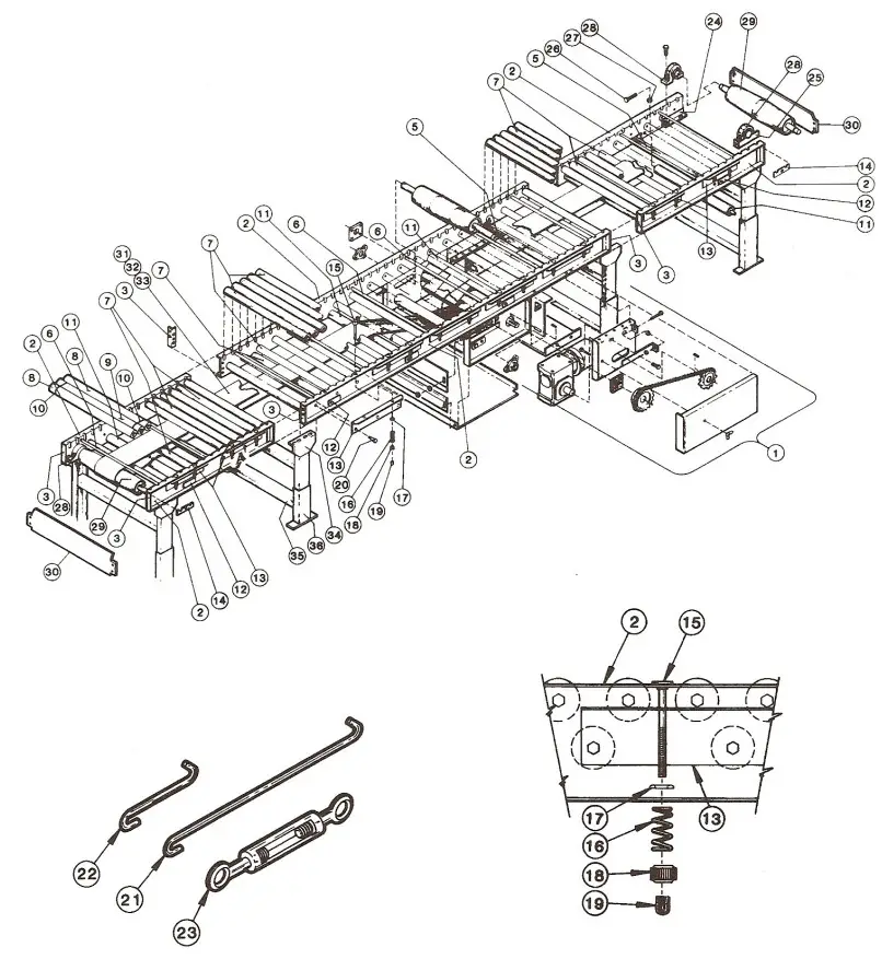 ● Model 190-ACZ Parts List
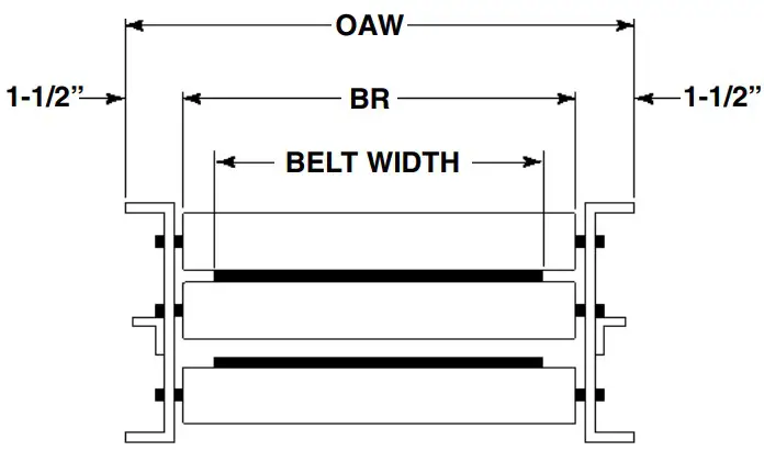
| BR | 13” | 15” | 17” | 19” | 21” | 23” | 25” | 27” | 31” | 33” | 37” | 39” |
| BELT WIDTH | 6” | 6” | 8” | 8” | 8” | 12” | 12” | 12” | 16” | 16” | 16” | 16” |
| OAW | 16” | 18” | 20” | 22” | 24” | 26” | 28” | 30” | 34” | 36” | 40” | 42” |
| Ref. No. | Part No. | Description |
| 1 | — | Drive Assembly (See pages 38 & 39) |
| 2 | — | Frame Channel—3 in. Roller Centers |
| — | B-05730 | 4 ft. Long |
| — | B-05731 | 5 ft. Long |
| — | B-05732 | 6 ft. Long |
| — | B-05733 | 7 ft. 6 in. Long |
| — | B-05734 | 8 ft. Long |
| — | B-17619 | 9 ft. Long |
| — | B-05735 | 10 ft. Long |
| 3 | B-03191 | Butt Coupling Plate |
| 5 | B-03916 | Bed Spacer (Specify BR) |
| 6 | B-05477 | Threaded Section Spacer (Specify BR) |
| 7 | B-01982 | 1.9 in. Dia. Galvanized Roller (Specify BR) |
| 8 | B-06535 | 1.9 in. Dia. Galv. Roller—One Groove (Specify BR) |
| 9 | B-21914 | 1.9 in. Dia. Galv. Roller—Two Grooves (Specify BR) |
| 10 | 090.255 | O-Ring |
| 11 | B-03894 | 2-1/8 in. Dia. Snub Roller (Specify BR) |
| 12 | B-00944 | 7/16 in. Hex Idler Bracket |
| 13 | — | Suspension Angle |
| — | B-05736 | 2 Roller |
| — | B-02448 | 3 Roller |
| — | B-02449 | 4 Roller |
| 14 | B-05588 | Roller Bracket—3 in. Roller Centers |
| 15 | 042.552 | Carraige Bolt—1/4-20 x 4 in. Long |
| 16 | 093.106 | Roller Suspension Spring |
| 17 | 043.400 | Finishing Washer—#12 |
| 18 | 041.901 | Knurled Adjusting Nut—1/4-20 x 4 in. Long |
| 19 | 090.220 | Red Vinal Plastisol Cap |
| 20 | 042.914 | Shoulder Bolt |
| 21 | 044.120 | Cross Brace Rod—70 in. Long |
| 22 | 044.121 | Cross Brace Rod—6 in. Long |
| 23 | 049.308 | Turnbuckle |
| 24 | B-05740 | Take-Up Bracket Assembly—RH |
| 25 | B-05743 | Take-Up Bracket Assembly—LH |
| Ref. No. | Part No. | Description |
| 26 | 040.305 | Take-Up Bolt—3/8-16 x 1-1/2 in. Long. |
| 27 | 041.300 | Hex Jam Nut—Heavy—3/8-16 |
| 28 | 010.3011 | Pillow Block Bearing—1 in. Bore |
| 29 | B-21185 | 4 in. Dia. Tail Pulley (Specify BR) |
| 30 | B-09800 | End Guard (Specify OAW) |
| 31 | — | Belt-Black Ultimate 140 BOS (Specify Width) |
| 32 | — | U3-1 Clipper Unibar Belt Lacing (Specify Length) |
| 33 | — | #13 LUB Lacing Pin (Specify Length) |
| 34 | — | MS Type Pivot Plate—1-1/2 in. Flange |
| — | B-00913 | 3-11/16 in. High |
| — | B-02112 | 1-9/16 in. High |
| 35 | — | Floor Support Frame |
| — | B-00914 | 6 in. High (Specify OAW) |
| — | B-12777 | 7 in. High (Specify OAW) |
| — | B-12778 | 8 in. High (Specify OAW) |
| — | B-00915 | 9 in. High (Specify OAW) |
| — | B-00916 | 11-1/2 in. High (Specify OAW) |
| — | B-00917 | 14-1/2 in. High (Specify OAW) |
| — | B-02098 | 18-1/2 in. High (Specify OAW) |
| — | B-00919 | 22-1/2 in. High (Specify OAW) |
| — | B-00921 | 32-1/2 in. High (Specify OAW) |
| — | B-00923 | 44-1/2 in. High (Specify OAW) |
| — | B-00925 | 56-1/2 in. High (Specify OAW) |
| — | B-02107 | 68-1/2 in. High (Specify OAW) |
| — | B-02109 | 78-1/2 in. High (Specify OAW) |
| — | B-02111 | 90-1/2 in. High (Specify OAW) |
| 36 | B-00911 | Adjustable Foot Assembly (Specify Length) |
● 8” Center Drive Parts Drawing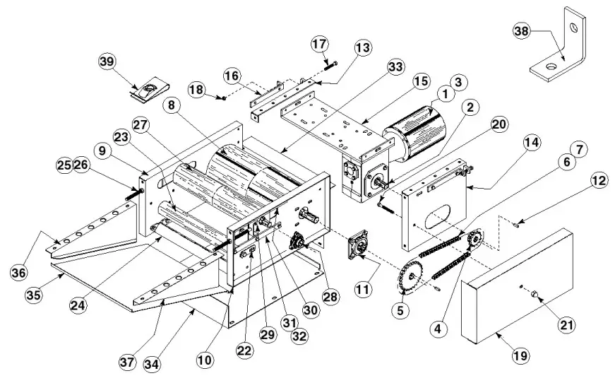 8” Center Drive Parts
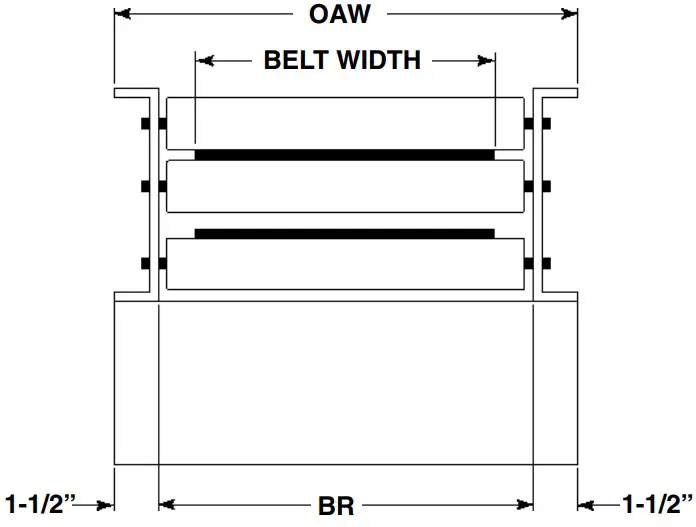
See Page 32 for Information on How To Order Replacement Parts
Recommended Spare Parts Highlighted in Gray
| BR | 13” | 15” | 17” | 19” | 21” | 23” | 25” | 27” | 31” | 33” | 37” | 39” |
| BELT WIDTH | 6” | 6” | 8” | 8” | 8” | 12” | 12” | 12” | 16” | 16” | 16” | 16” |
| OAW | 16” | 18” | 20” | 22” | 24” | 26” | 28” | 30” | 34” | 36” | 40” | 42” |
| Ref. No. | Part No. | Description |
| 1 | — | Motor—C-Face |
| — | 030.7134 | 1/2 HP—230/460VAC—3 Ph.—60 Hz.—TEFC |
| — | 030.7324 | 1 HP—230/460VAC—3 Ph.—60 Hz.—TEFC |
| — | 030.7534 | 2 HP—230/460VAC—3 Ph.—60 Hz.—TEFC |
| 2 | — | Speed Reducer |
| — | R-00153-30R | 4AC—RH—30:1 Ratio |
| — | R-00164-30R | 5AC—RH—30:1 Ratio |
| 3 | — | Coupling Kit—Motor to Reducer |
| — | 052.145 | 1/2—1 HP |
| — | 052.146 | 2 HP |
| 4 | — | Sprocket—Reducer |
| — | 028.133 | 50B14 x 1 in. Bore (4AC) |
| — | 028.1342 | 50B16 x 1-1/4 in. Bore (5AC) |
| 5 | — | Sprocket–Drive Pulley |
| – | 028.13832 | 50B28 x 1-3/16 in. Bore (4AC) |
| – | 028.1115 | 50B32 x 1-3/16 in. Bore (5AC) |
| 6 | 029.101 | #50 Riveted Roller Chain |
| 7 | 029.201 | Connector Link–#50 Roller Chain |
| 8 | B-02021 | 8 in. Dia. Ctr. Dr. Pulley (Fully Lagged) (Sp. Dr. Width) |
| 9 | B-05961 | Drive Plate Assembly–RH |
| 10 | B-05963 | Drive Plate Assembly–LH |
| 11 | 010.202 | 4-Bolt Flange Bearing–1-3/16 in. Bore |
| 12 | 090.203 | Shaft Key–1/4 in. Sq. x 1 in. Long |
| 13 | B-05946 | Motor Base Support Angle Assembly |
| 14 | B-05943 | Motor Support Assembly |
| 15 | B-06629 | Motor Base Assembly (Specify Drive Width) |
| 16 | B-05965 | Take-Up Bracket |
| 17 | 040.307 | Take-Up Bolt–3/8-16 x 2-1/4 in. Long |
| Ref. No. | Part No. | Description |
| 18 | 041.300 | Hex Jam Nut–Heavy–3/8-16 |
| 19 | B-05949 | Chain Guard Assembly |
| 20 | 040.3111 | Hex Head Cap Screw—3/8-16 x 3-1/4 in. Long |
| 21 | 041.919 | Acorn Nut—3/8-16 |
| 22 | B-04842 | 11/16 in. Hex Idler Bracket |
| 23 | B-17254 | 2-1/2 in. Dia. Heavy Duty Snub Idler (Specify BR) |
| 24 | B-03916 | Bed Spacer (Specify BR) |
| 25 | 040.411 | Take-Up Bolt—1/2-13 x 9 in. Long |
| 26 | 041.201 | Hex Jam Nut—1/2-13 |
| 27 | — | 4 in. Dia. Take-Up Pulley |
| — | B-22323 | 16”and 18” OAW (Specify) |
| — | B-05904 | 20 in. thru 42 in. Drive Width (Specify) |
| 28 | 010.102 | 3-Bolt Flange Bearing—1 in. Bore |
| 29 | B-05958 | Take-Up Plate Assembly |
| 30 | B-05966 | Upper Bearing Guide |
| 31 | B-04655 | Bearing Guide Spacer |
| 32 | B-04161 | Bearing Guide |
| 33 | B-08336 | Rear Guard (Specify Drive Width) |
| 34 | B-08335 | Bottom Guard (Specify Drive Width) |
| 35 | B-08337 | Bottom Angle Guard (Specify Drive Width) |
| 36 | B-08338-R | Side Guard—RH |
| 37 | B-08338-L | Side Guard—LH |
| 38 | B-08339 | Formed Clip |
| 39 | 049.310 | U-Type Speed Nut—1/4-20 |
![]() Powered by conveyor solutions
Powered by conveyor solutions
“Building Relationships One Conveyor Part at a Time”
[email protected] | www.HytrolParts.com
Use code HYPMANUAL for free shipping on your first order at HytrolParts.com


