EATON PUB53683 PowerXL DM1 Option Cards
Installation steps
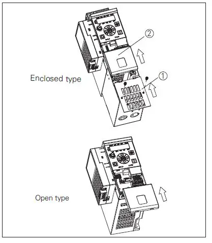
Step 1.
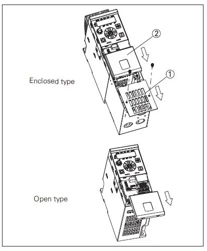
For enclosed type:
- Remove the front cover ① from the NEMA 1 kit.
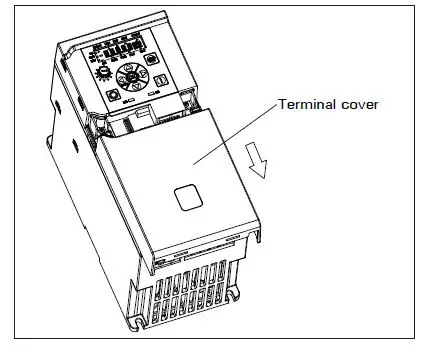
- Remove the terminal cover ② from the drive.
For open type:
- Only remove the terminal cover ② from the drive.

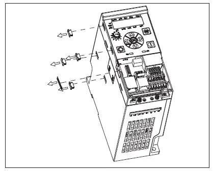
Step 2.
- Remove the option card port label and four snap covers from the drive.

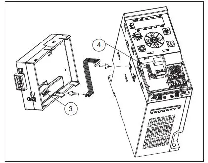
Step 3.
- Connect the cable to option card connector ③ and MCU board connector ④.

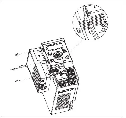
Step 4.
- Clamp the cable with optional card port.
- Mount the option card to the drive by inserting the four snaps into the slots on drive.

Step 5.
For enclosed type:
- Install the terminal cover ② to the drive.
- Install the front cover ① to the NEMA 1 kit.
For open type:
- Only install the terminal cover ② to the drive.
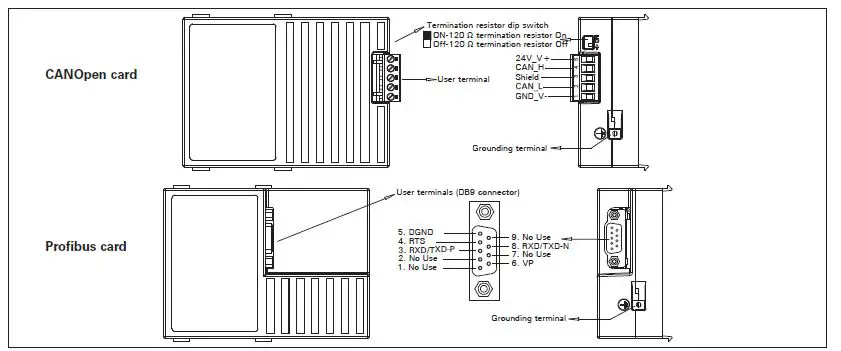
Wiring instruction
Smartwire kit installation
Component lists
IP20 Smartwire kit
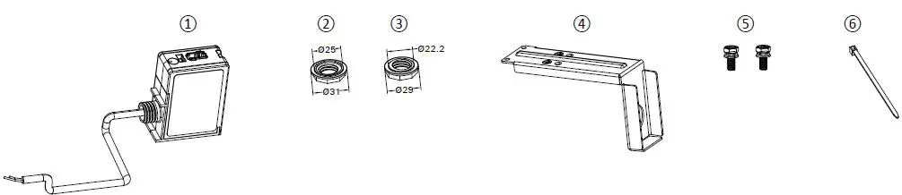
- Smartwire module (DXG-NET-SWD-IP20)
- EN version nut
- US version nut
- Metal adapter plate
- M3*8 screws
- Cable tie
Note: Parts 1, 2, 3, and 6 are used for all DG1/DH1/DM1 drives. Note: Parts 4 and 5 are only used for DM1 open type drives.
IP54 Smartwire kit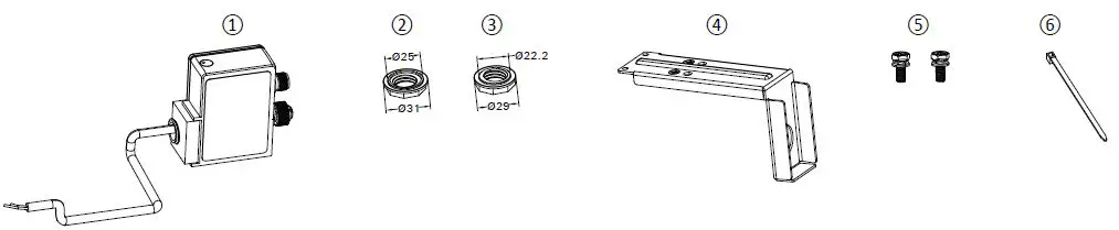
- Smartwire module (DXG-NET-SWD-IP54)
- EN version nut
- US version nut
- Metal adapter plate
- M3*8 screws
- Cable tie
Note: Parts 1, 2, 3, and 6 are used for all DG1/DH1/DM1 drives. Note: Parts 4 and 5 are only used for DM1 open type drives.
Smartwire kit installation steps
Step 1.
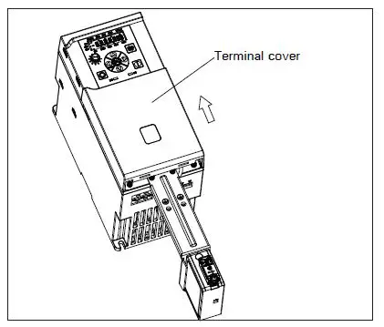
- Remove the terminal cover from the drive.

Step 2.
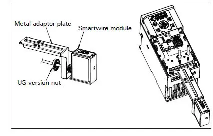
- Run the smartwire module cable through the metal adapter plate conduit hole. Lock the module with the US version plastic nut.
- Mount the adapter plate and smartwire module on the drive ground plate with two M3*8 screws torqued to 0.8 N.m(7 lb-in).

Step 3.
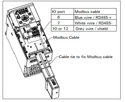
- Connect the Modbus cable to MCU board IO terminals.
- Use a cable tie to fix the Modbus cable to adapter plate.

Step 4.
- Mount the terminal cover back on the drive.

Step 5.
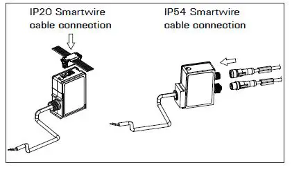
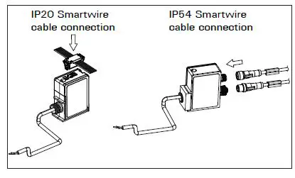
- Connect the communication cable (ribbon cable for IP20 smart wire kit, round cable for IP54 smartwire kit) to the smartwire module.

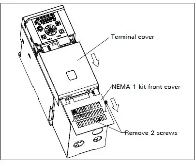
Smartwire NEMA kit installation steps
Step 1.
- Remove the NEMA 1 kit front cover.
- Remove the terminal cover from the drive.c

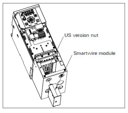
Step 2.
- Insert the smartwire module cable into the top left conduit hole.
- Lock the module with the US version plastic nut.

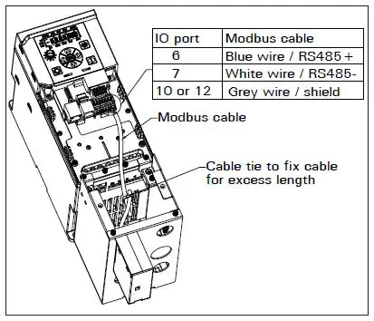
Step 3.
- Connect the Modbus cable to the MCU board IO terminals.
- Use a cable tie to fix the Modbus cable for excess length.


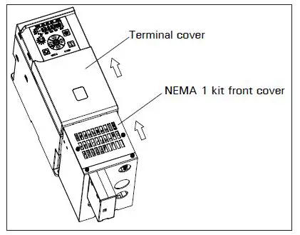
Step 4.
- Mount the terminal cover back on the drive.
- Mount the NEMA 1 kit front cover back on the NEMA 1 kit.
Step 5.
- Connect the communication cable (ribbon cable for IP20 smart wire kit, round cable for IP54 smart wire kit) to the smartwire module.