VIDEX 2313 Remote Relay for VX2300 system User Manual
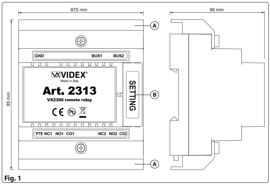
DIMANSION PRODUCT
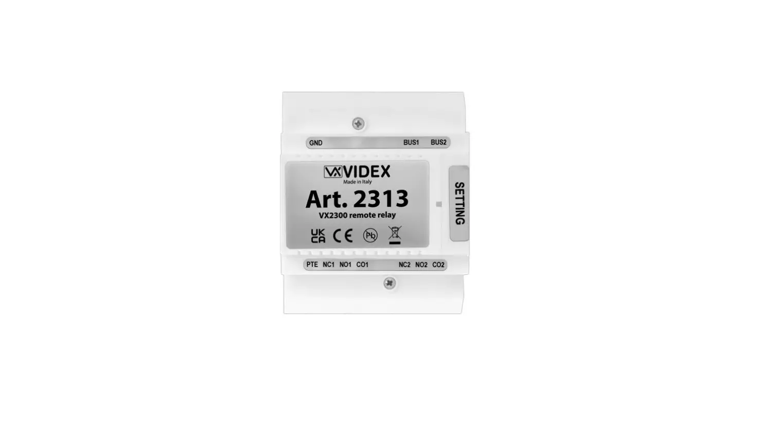
DESCRIPTION
Remote relay for VX2300 system.
All entrance panels on the VX2300 system include the lock release relay and push to exit button input inside the entrance panel. For higher security applications including installations in compliance with ‘Secured By Design’ the 2313 enables the relay and push to exit button input 1 to be installed in a secure location away from the entrance. There is also a second relay that can be activate pressing the service button present in every VX2300 phone or videophone.
LEGEND
A Connection terminals covers
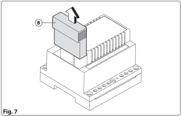
B Dip-switch cover
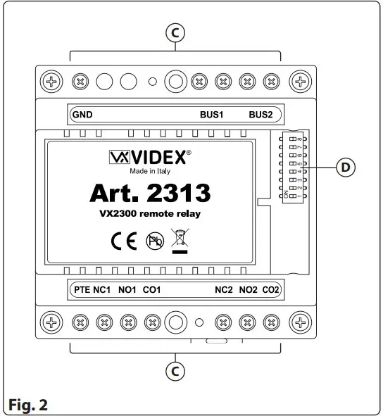
C Connection terminals
D 8 way dip-switch
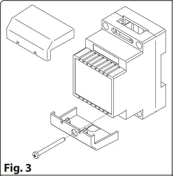
- Remove the terminal side covers by unscrewing the retaining screws (Fig. 3).

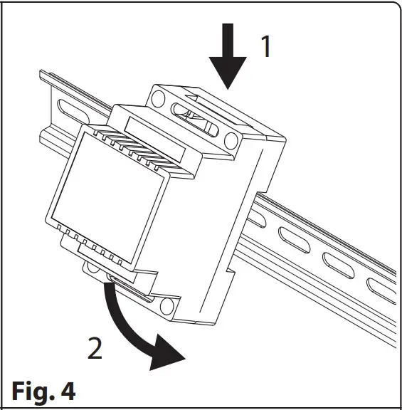
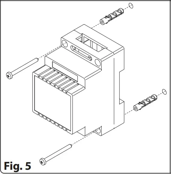
- Fix the device to a DIN rail (Fig. 4) or directly to the wall using two expansion type screws (Fig. 5).

- Isolate the mains using the circuit breaker mentioned above then make the connections as shown on the installation diagrams (if provided).
- Check all connections and secure the wires into the terminals;
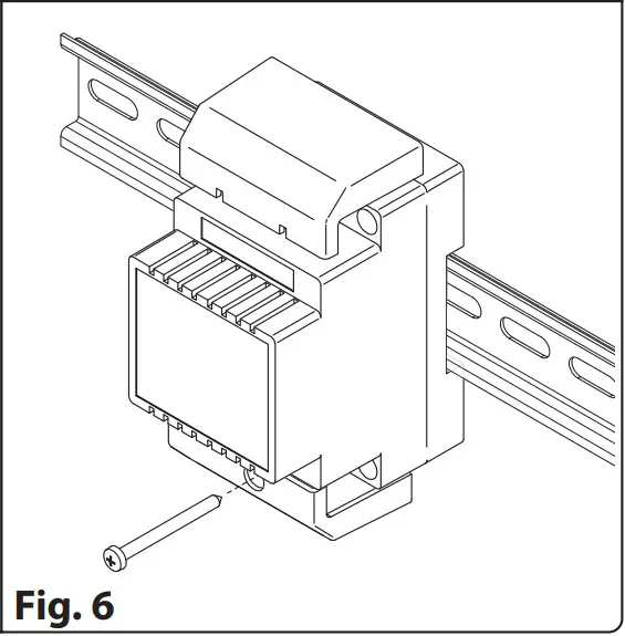
- When all connections are made replace and fix the terminal covers with the relevant screws (Fig. 6).
- Restore the mains.
- Programming is made by dip-switch D accessible by lifting up the cover B (Fig. 7).

PROGRAMMING RELATED TO OUTDOOR STATION ADDRESS
| Switch | Nr.1 | Nr.2 | Nr.3 | Nr.4 | ID |
| OFF | OFF | OFF | OFF | 1 | |
| ON | OFF | OFF | OFF | 2 | |
| OFF | ON | OFF | OFF | 3 | |
| ON | ON | OFF | OFF | 4 | |
| OFF | OFF | ON | OFF | 5 | |
| ON | OFF | ON | OFF | 6 | |
| OFF | ON | ON | OFF | 7 | |
| ON | ON | ON | OFF | 8 | |
| OFF | OFF | OFF | ON | 9 | |
| ON | OFF | OFF | ON | 10 | |
| OFF | ON | OFF | ON | 11 | |
| ON | OFF | ON | ON | 12 | |
| OFF | OFF | ON | ON | 13 | |
| ON | OFF | ON | ON | 14 | |
| OFF | ON | ON | ON | 15 |
RELAY 1 TIME
PTE teminal open Relay 1 for the setted time.
| Switch | Nr.5 | Nr.6 | Setting Up |
| OFF | OFF | = 2 seconds | |
| OFF | ON | = 8 seconds | |
| ON | OFF | = 16 seconds | |
| ON | ON | = 32 seconds |
CONNECTION TERMINALS
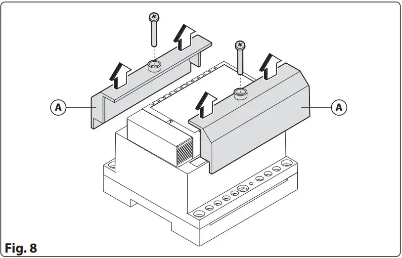
To access to the connection terminals, first remove both the retaining screws, then the covers A (Fig. 8).
| GND | Ground |
| BUS1 | BUS Input/Output |
| BUS2 | BUS Input/Output |
| PTE | Open relay 1 for the setted time | Max 24Vac/dc 5A |
| NC1 | Relay 1 normally closed contact | |
| NO1 | Relay 1 normally open contact | |
| CO1 | Relay 1 common contact | |
| NC2 | Relay 2 normally closed contact | |
| NO2 | Relay 2 normally open contact | |
| CO2 | Relay 2 common contact |
TECHNICAL SPECIFICATIONS
Housing/Mounting: 5 module A type DIN box DIN bar or directly to the wall
Dry contacts relay: Max 24Vac/dc 5A
Power supply: Supplied by the BUS line
Working temperature: -20 +60°C


