![]() 2813 RS485 Remote Relay
2813 RS485 Remote Relay
Instructions
![]()
Accessories
Art. 2813 RS485
Remote Relay – Rev.0.1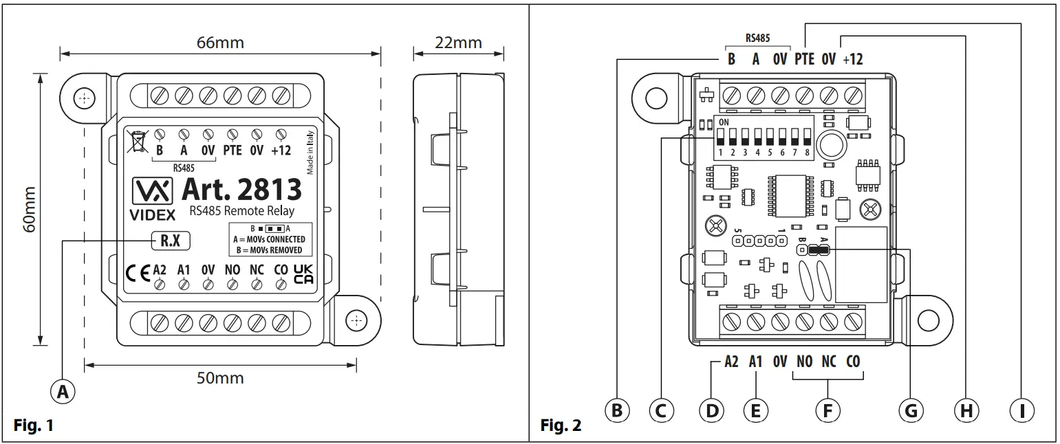
DESCRIPTION
The Art.2813 is a networkable RS485 remote relay, Fig.1. It is compatible with other Videx devices which incorporates an RS485 bus connection, for example Videx’s 4G GSM intercoms and IP system devices.
When connected via the RS485 bus (Fig.2, ) it can be integrated as part of an access control network with other Art.2813 remote relays or with 4903 keypads and 4850R proximity readers (also refer to Fig.9 wiring diagram example). It has a single onboard relay with normally open (NO), normally closed (NC) and common (CO) connections and two switched 0V auxiliary outputs A1 and A2 (Fig.2, and ).
LEGEND
A Firmware version – R.X
B RS485 bus terminals
C 8 way programmable dip switches
D Auxiliary output A2
E Auxiliary output A1
F Relay (CO/NC/NO) terminals
G Back EMF protection jumper JP
H +12Vdc power input
I PTE input (switched 0V)
The relay and both auxiliary outputs operating times can be programmed from 1 – 63 seconds or 0 for latch mode by using switches 1 – 6 on the 8 way dip-switch (Fig.2, ).
It also includes a switched 0V push to exit input PTE (Fig.2, ) that when activated via a push to exit button (configured as a push- to-make switch) will operate the relay for the programmed time. It should be noted that when the relay time has been set for latch mode an exit button, connected across 0V and PTE, will operate as a “toggle” switch to latch the relay open and closed. Similarly both the auxiliary outputs A1 and A2, when set to latch mode, will also operate as a “toggle” switched 0V output.
PROGRAMMING
Programming of the remote relay is carried out using the 8 way dip-switch (Fig.2, ) where up to 64 device ID’s (from ID.00 to ID.63) can be set and where relay operating times and auxiliary output times (for A1 and A2) can be set. Further programming notes can be found on pages 2 and 3.
OPERATION
As mentioned above the relay can be activated directly via the PTE input. When incorporated as part of a GSM system the relay can be triggered remotely via text message or by using the Videx GSM mobile apps. Also the auxiliary outputs A1 and A2 can be activated via text message or by using the Videx GSM mobile apps. Further operational notes can be found in the GSM apps themselves or any of the latest GSM manuals.
The relay and auxiliary outputs A1 and A2 can also be remotely activated from a Videx IP system device (e.g. IP audio or video entry panels, IP audiophone or IP videophones. Also refer to Fig.11 wiring diagram example) after the IP device’s output has been configured (further notes on IP system output configuration can be found in any of the IP system manuals).
SECURED BY DESIGN
If the remote relay is setup with the same device ID as one of the 4G GSM intercoms i.e. ID.1 or setup with the same device ID as a 4903 keypad or 4850R proximity reader it will then mirror their respective outputs (for the 4G GSM’s it will mirror the relay and auxiliary outputs and for the 4903 and 4850R it will mirror the relay outputs) allowing for a Secured by Design configuration (also refer to Fig.10 wiring diagram example).
BACK EMF PROTECTION JUMPER JP
The onboard relay contacts NO and NC have built-in back EMF protection which can be adjusted using the internal MOV jumper JP (Fig.2,).
When set to the A position (default) the internal MOV’s are connected across the CO to NO and CO to NC relay contacts, Fig.3.
When set to the B position the MOV’s are disconnected (removed) from the NO and NC relay contacts (suitable if connecting the relay to an electric gate input), Fig.3.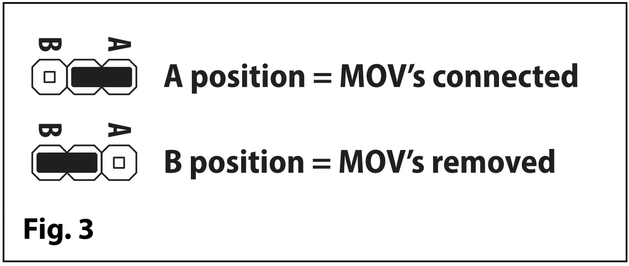
PROGRAMMING VIA THE DIP-SWITCHES
IMPORTANT NOTE: Please note that the black area represents the dip-switch position:![]()
Switches 1 to 6 on the 8 way dip-switch (Fig.2, ) are used to setup the device ID (ID.00 – ID.63), the relay time and auxiliary A1 and A2 times (in seconds) for the remote relay and is located under the top enclosure cover. Switches 7 and 8 determines which parameter is being set, i.e. 7=ON and 8=OFF would set auxiliary A1 time.
Each switch corresponds to one bit which can have a value 0 (OFF) or 1 (ON). Each bit corresponds to a decimal weight depending on the position: switch 1 = decimal 1, 2=2, 3=4, 4=8, 5=16 and 6=32, i.e. to set the device ID to ID.37, put switches 1, 3 and 6 ON (1+4+32=37), see table below.
| SWITCHES | DECIMAL WEIGHT | RELAY, Al, A2 TIME & DEVICE ID | ||||||||||
| 6 | 5 | 4 | 3 | 2 | 1 | 32 | 16 | 8 | 4 | 2 | 1 | |
| OFF | OFF | OFF | OFF | OFF | OFF | 0 | 0 | 0 | 0 | 0 | 0 | 0 |
| OFF | OFF | OFF | OFF | OFF | ON | 0 | 0 | 0 | 0 | 0 | 1 | 1 |
| OFF | OFF | OFF | OFF | ON OFF | 0 | 0 | 0 | 0 | 1 | 0 | 2 | |
| OFF | OFF | OFF | OFF | ON | ON | 0 | 0 | 0 | 0 | 1 | 1 | 3 |
| ON OFF OFF I ON I OFF | ON | 1 | 0 | 1 | 0 | 1 | 37 | |||||
| ON | ON | I ON | I ON | I ON I | ON | 1 | 1 | 1 | 1 | 1 | 1 | 63 |
SETTING THE RELAY TIME (1 – 63 SECS, 0 = LATCH MODE)
The relay time can be set between 1 up to 63 seconds or can be set to latch mode, i.e. the relay time is set to 0, by using the switches 1 to 6 on the 8 way dip-switch (Fig.2, ).
In order to setup the relay time follow the steps below: 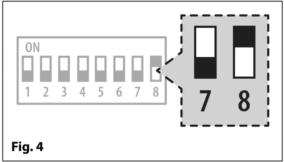
- Disconnect the power to the remote relay.
- Set dip-switches 7 to the OFF position and 8 to the ON position, see Fig.4.
- Use dip-switches 1 to 6 to set the relay time, following the same methodology used when setting up the device ID.
- Once the desired relay time is set reconnect the power to the remote relay.
- Wait a couple of seconds then power down again. The relay time is saved to the onboard non-volatile memory.
SETTING AUXILIARY A1 TIME (1 – 63 SECS, 0 = LATCH MODE)
Auxiliary A1 time can be set between 1 up to 63 seconds or can be set to latch mode, i.e. the auxiliary A1 time is set to 0, by using the switches 1 to 6 on the 8 way dip-switch (Fig.2, ). When auxiliary A1 is activated remotely it will switch 0V for the programmed time.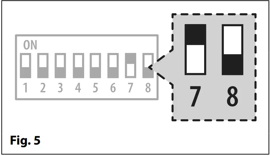 In order to setup auxiliary A1 time follow the steps below:
- Disconnect the power to the remote relay.
- Set dip-switches 7 to the ON position and 8 to the OFF position, see Fig.5.
- Use dip-switches 1 to 6 to set the relay time, following the same methodology used when setting up the device ID.
- Once the desired relay time is set reconnect the power to the remote relay.
- Wait a couple of seconds then power down again. The relay time is saved to the onboard non-volatile memory.
SETTING AUXILIARY A2 TIME (1 – 63 SECS, 0 = LATCH MODE)
Auxiliary A2 time can be set between 1 up to 63 seconds or can be set to latch mode, i.e. the auxiliary A2 time is set to 0, by using the switches 1 to 6 on the 8 way dip-switch (Fig.2, ). When auxiliary A2 is activated remotely it will switch 0V for the programmed time.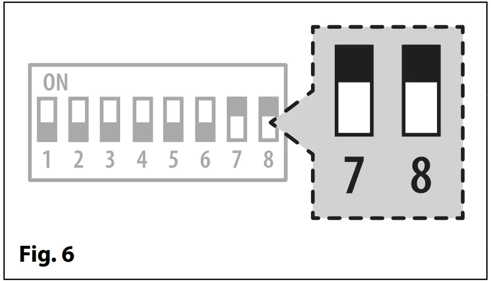
In order to setup auxiliary A2 time follow the steps below:
- Disconnect the power to the remote relay.
- Set dip-switches 7 and 8 to the ON position, see Fig.6.
- Use dip-switches 1 to 6 to set the relay time, following the same methodology used when setting up the device ID.
- Once the desired relay time is set reconnect the power to the remote relay.
- Wait a couple of seconds then power down again. The relay time is saved to the onboard non-volatile memory.
SETTING THE DEVICE ID (ID.00 – ID.63)
The relay’s device ID can be set between ID.00 up to ID.63 by using the switches 1 to 6 on the 8 way dip-switch (Fig.2, ) and where the ID is addressed in binary. IMPORTANT NOTE: The device ID should always be setup last.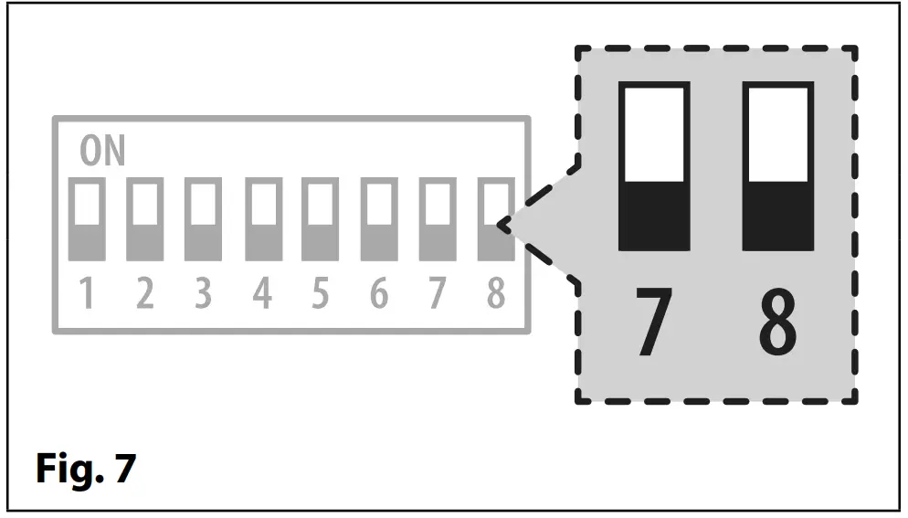 In order to setup the device ID follow the steps below:
- Disconnect the power to the remote relay.
- Set dip-switches 7 and 8 to the OFF position, see Fig.7.
- Use dip-switches 1 to 6 to set the device ID, following the examples in the table above.
- Once the desired device ID is set reconnect the power to the remote relay. The device ID is read when the remote relay is powered back up.
RS485 BUS TERMINATION
If the remote relay is the end of line device on the RS485 bus a 120Ω resistor must be fitted across the RS485 bus terminals A and B, as shown in Fig.8, but only over a great distance (up to 500m max.). Over shorter distances (approximately 100m or so) a 120Ω resistor will not be required.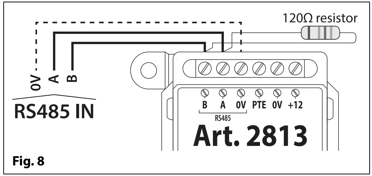
TERMINAL CONNECTIONS
| Connection | Description | |
| B | RS485 bus terminal connections | |
| A | ||
| OV | RS485 OV ground connection | |
| PTE | Push to Exit input (switched OV) | |
| OV | OV power input | |
| +12 | 12Vdc power input | |
| A2 | Auxiliary output A2 | |
| Al | Auxiliary output Al | |
| OV | OV ground connection | |
| NO | Relay normally open connection | 3A @ 24Va c/dc |
| NC | Relay normally closed connection | |
| CO | Relay common connection | |
TECHNICAL SPECIFICATION
| Working voltage: | 12Vdc +/- 10% |
| Current (standby): | 5mA |
| Current (operation): | 34mA (max.) |
| Number of relays: | 1x, C, NC and NO |
| Relay current / voltage: | 3A @ 24Vac/dc (max.) |
| Push to exit input: | PTE for relay only (switched 0V) |
| Auxiliary outputs: | A1 and A2 (both switched 0V) |
| Back EMF protection: | Yes, via MOV jumper JP |
| RS485 bus connections: | A, B and 0V (GND) |
| Networkable: | via RS485 (up to 64 devices max.) |
| Programming: | via 8 way internal dip-switches for device ID, relay & aux. times |
| Working Temperature: | -20 +60oC |
![]() IT IS RECOMMENDED THAT THIS VIDEX PRODUCT IS INSTALLED BY A COMPETENT AND QUALIFIED ELECTRICIAN, SECURITY INSTALLATION SPECIALIST OR COMMUNICATIONS ENGINEER.
IT IS RECOMMENDED THAT THIS VIDEX PRODUCT IS INSTALLED BY A COMPETENT AND QUALIFIED ELECTRICIAN, SECURITY INSTALLATION SPECIALIST OR COMMUNICATIONS ENGINEER.
WIRING DIAGRAMS
Below Fig.9 shows how the remote relay can be integrated as part of a networkable access control system.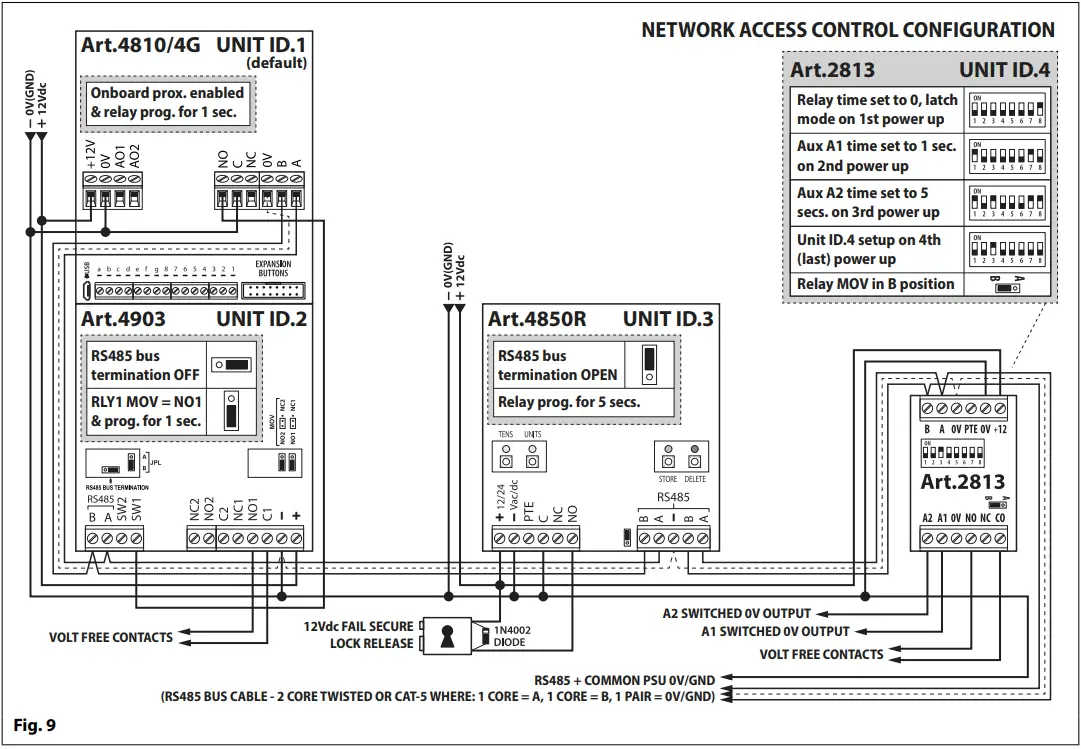 Below Fig.10 shows how the remote relay can be configured as a Secured by Design system with a 4G GSM intercom.
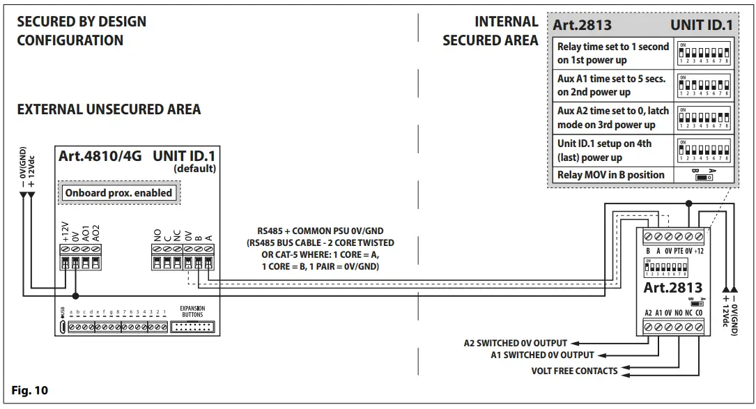 Below Fig.11 shows how the remote relay can be integrated as part of an IP video system.
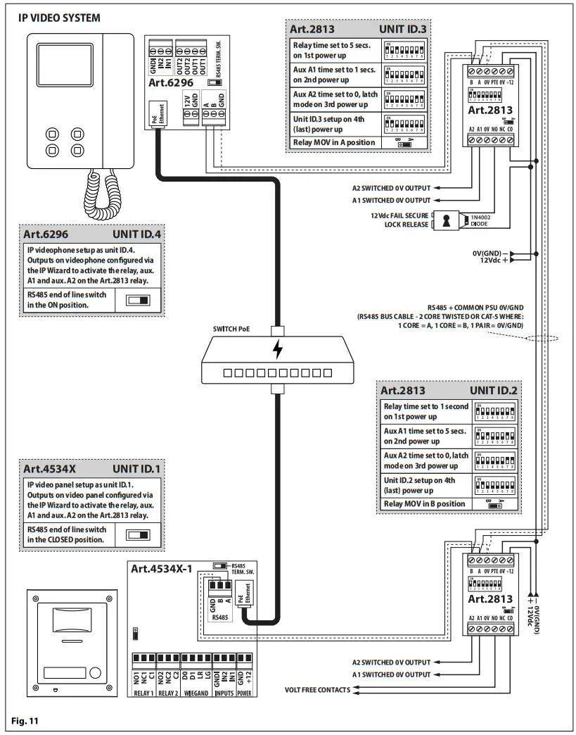
DISPOSAL
![]() In accordance with the Legislative Decree no. 49 of 14 March 2014 “Implementation of the Directive 2012/19/EU on waste electrical and electronic equipment (WEEE)”.
In accordance with the Legislative Decree no. 49 of 14 March 2014 “Implementation of the Directive 2012/19/EU on waste electrical and electronic equipment (WEEE)”.
The crossed-out bin symbol on the equipment or on the packaging indicates that when the product reaches the end of its lifetime, it must be collected separately from mixed municipal waste. The user must, therefore, dispose of the equipment at the end of its lifetime in the suitable waste collection centres or bring it to the retailer during the purchase of a new equipment of equivalent type at the ratio of one-to-one. Furthermore,the user is allowed to dispose of the WEEEs of very small size (domestic appliances without any external dimension exceeding 25 cm (9.84 inches) for free to the retailers, without any purchase obligation. The correct waste disposal of the WEEEs contributes
to their reuse, recycling and recovery and avoids potential negative effects on the environment and human health due to the possible presence of dangerous substances within
them.
| MANUFACTURER | VIDEX ELECTRONICS S.P.A. Via del Lavoro, 1 63846 Monte Giberto (FM) Italy Tel (+39) 0734 631669 Fax (+39) 0734 632475 www.videx.it – [email protected] |
| CUSTOMER SUPPORT | VIDEX ELECTRONICS S.P.A. www.videx.it [email protected] Tel: +39 0734-631669 Fax: +39 0734-632475 |
UK Customers only:
VIDEX SECURITY LTD
www.videxuk.com
Tech Line: 0191 224 3174
[email protected]
| Portugal office: VX IBÉRIA, UNIPESSOAL LDA Rua Tenente Mário Grilo, 26 D, E, F 4200-397 Porto Phone: (+351) 221 124 531 www.videx.it [email protected] | Singapore office: VIDEX ASIA PACIFIC PTE LTD 1 TAMPINES NORTH DRIVE 1, #06-08, T-Space Singapore 528559 Phone: (+65) 81898912 [email protected] |
| Main UK office: VIDEX SECURITY LTD 1 Osprey Trinity Park Trinity Way LONDON E4 8TD Phone: (+44) 0370 300 1240 www.videxuk.com [email protected] | Northern UK office: VIDEX SECURITY LTD Unit 4-7 Chillingham Industrial Estate Chapman Street NEWCASTLE UPON TYNE – NE6 2XX Tech Line: (+44) 0191 224 3174 Phone: (+44) 0370 300 1240 |
| Greece office: VIDEX HELLAS Electronics 48 Filolaou Str. 11633 ATHENS Phone: (+30) 210 7521028 (+30) 210 7521998 Fax: (+30) 210 7560712 www.videx.gr [email protected] | Danish office: VIDEX DANMARK Hammershusgade 15 DK-2100 COPENHAGEN Phone: (+45) 39 29 80 00 Fax: (+45) 39 27 77 75 www.videx.dk [email protected] |
| Benelux office: NESTOR COMPANY NV E3 laan, 93 B-9800 Deinze Phone: (+32) 9 380 40 20 Fax: (+32) 9 380 40 25 www.nestorcompany.be [email protected] | Dutch office: NESTOR COMPANY BV Business Center Twente (BCT) Grotestraat, 64 NL-7622 GM Borne www.videxintercom.nl [email protected] |
The product is CE marked demonstrating its conformity and is for distribution within all member states of the EU with no restrictions. This product follows the provisions of the European Directives 2014/30/EU (EMC); 2014/35/EU (LVD); 2011/65/EU (RoHS): CE marking 93/68/EEC.
References
 Hoge kwaliteitsoplossingen op maat - Snelle en betrouwbare service voor de professional - Jarenlange ervaring en expertise
-
Dørtelefoner fra Videx | Få din dørtelefon eller anlæg opdateret.
 ΘΥΡΟΤΗΛΕΟΡΑΣΗ ΘΥΡΟΤΗΛΕΟΡΑΣΕΙΣ VIDEX
-
Homepage - Videx Electronics Spa
 Videx Security - Access anytime, anywhere.


