
Panasonic SFM Relay
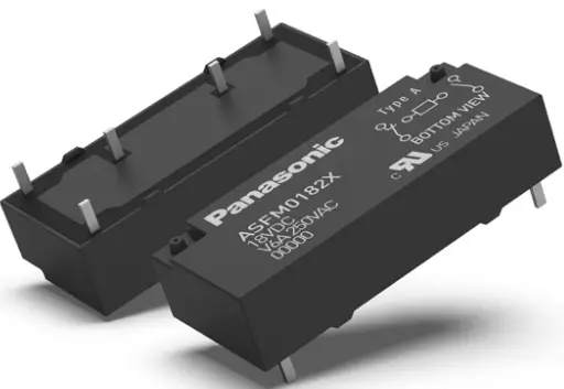
Compact Relay with Forcibly Guided Contacts
FEATURES
- Forcibly guided contact structure complies with EN 61810-1 & EN 61810-3, Type A, enables detection of contact welding and construction of safety circuit
- All contacts qualified according to AC15, DC13 and B300, R300 @ 85°C
- Size:
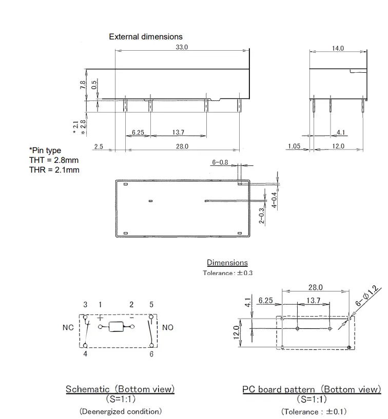
Type L ´ W ´ H (mm inch) 1 Form A 1 Form B THT /THR 33´14.0´7.8 [including 0.5mm stand-off
- Very low profile: 7.8 mm
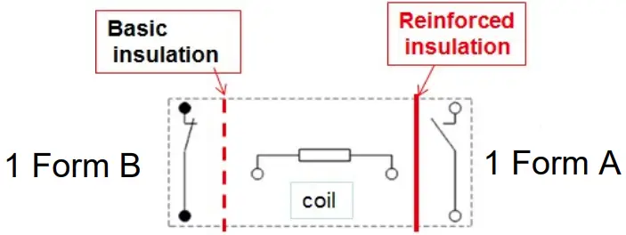
- Insulation according to EN 60664-1: Overvoltage category III, Pollution degree 2, 250V AC
Reinforced insulation: Clearance and creepage ≥ 5.5 mm .217 inch
(between NO and NC and between NO and coil)
Basic insulation:
Clearance ≥ 3 mm .118 inch and creepage ≥ 4 mm .157 inch between NC and coil) - Complies with IEC 61010 reinforced insulation standards
TYPICAL APPLICATIONS
- Emergency stop switches
- Machine safety engineering
- Safety control units
- Automation technology
- Elevators
- Escalators
- Safe sensor monitoring
- Standalone safety modules
- Safety sensor output
ORDERING INFORMATION
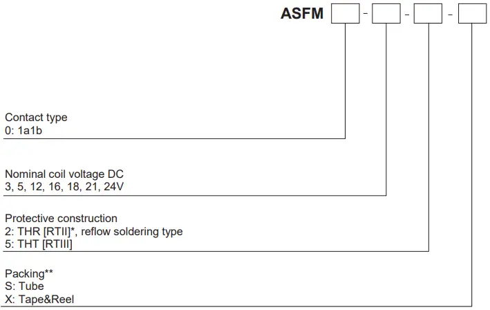
Notes: Please consult us about other coil voltages.
*: Breathing hole open (degree of protection RTII)
**: The “S” or “X” at the end of the part number only appears on the inner and outer packaging. It does not appear on the relay itself
TYPES
| Packaging | Relay Technology Categories | Nominal coil voltage | Part No. |
|
Tape |
RTII Reflow | 3 V DC | ASFM0032X |
| 5 V DC | ASFM0052X | ||
| 12 V DC | ASFM0122X | ||
| 16 V DC | ASFM0162X | ||
| 18 V DC | ASFM0182X | ||
| 21 V DC | ASFM0212X | ||
| 24 V DC | ASFM0242X | ||
|
Tube | 3 V DC | ASFM0032S | |
| 5 V DC | ASFM0052S | ||
| 12 V DC | ASFM0122S | ||
| 16 V DC | ASFM0162S | ||
| 18 V DC | ASFM0182S | ||
| 21 V DC | ASFM0212S | ||
| 24 V DC | ASFM0242S | ||
|
RTIII | 3 V DC | ASFM0035S | |
| 5 V DC | ASFM0055S | ||
| 12 V DC | ASFM0125S | ||
| 16 V DC | ASFM0165S | ||
| 18 V DC | ASFM0185S | ||
| 21 V DC | ASFM0215S | ||
| 24 V DC | ASFM0245S |
Standard packing: tube 20 pcs., tape&reel 250 pcs
RATING
Coil data
| Contact arrangement | Rated coil voltage | Operate voltage (at 20°C 68°F) | Release voltage (at 20°C 68°F) | Rated operating current [±10%] (at 20°C 68°F) | Coil resistance [±10%] (at 20°C 68°F) | Rated operating power (at 20°C 68°F) | Max. allowable voltage (at 20°C 68°F) |
|
1 form A 1 form B | 3V DC |
75%V or less of nominal voltage (Initial) |
10%V or more of nominal voltage (Initial) | 90 mA | 33.3 W |
270mW
100mW holding power |
120%V of rated voltage |
| 5V DC | 54 mA | 93 W | |||||
| 12V DC | 23 mA | 533 W | |||||
| 16V DC | 17 mA | 948 W | |||||
| 18V DC | 15 mA | 1200 W | |||||
| 21V DC | 13 mA | 1633 W | |||||
| 24V DC | 11 mA | 2133 W |
Specifications
| Characteristics | Item | Specifications | ||
| RTII | RTIII | |||
|
Contact | Contact arrangement | 1 Form A 1 Form B | 1 Form A 1 Form B | |
| Forcibly guided contacts | Type A, IEC EN 61810-1, EN 61810-3 | |||
| Contact resistance (Initial) | Max. 100 mW (by voltage drop 6 V DC 1A) | |||
| Contact material | Au-flashed AgNi | AgSnO2 | ||
|
Rating | Nominal switching capacity (resistive load) | 6A 250V AC, 6A 30V DC | ||
| Max. switching power (resistive load) | 1,500VA, 180W | |||
| Max. switching voltage | 250V AC, 125V DC | |||
| Max. switching current | NO: 6A NC: 4A | |||
| Min. switching capacity (Reference value)*1 | 1mA 10V | |||
|
Electrical characteristics | Breakdown voltage (Initial) | Between open contacts | 1,500 Vrms for 1 min. (Detection current: 10mA) | |
| Between contact and coil | NC: 2,500 Vrms for 1min; NO: 4,000 Vrms for 1min (Detection current: 10mA) | |||
| Coil holding voltage*2 | Min. 60%V (at 85°C 185°F, 6A) | |||
| Operate time (at 20°C 68°F) | Max. 15ms (Nominal coil voltage applied to the coil, excluding contact bounce time) | |||
| Release time (at 20°C 68°F) | Max. 10ms (Nominal coil voltage applied to the coil, excluding contact bounce time) (without diode) | |||
| Mechanical characteristics | Shock resistance | Functional | Min. 200 m/s2 {Min. 20G} (Half-wave pulse of sine wave: 11 ms; detection time: 10ms) | |
| Destructive | Min. 1,000 m/s2 (Half-wave pulse of sine wave: 6 ms) | |||
| Vibration resistance | Functional | 10 to 55 Hz at double amplitude of 1.5 mm .059 inch (Detection time: 10ms) | ||
| Destructive | 10 to 55 Hz at double amplitude of 1.5 mm .059 inch | |||
| Expected life | Mechanical | Min. 107 (at 180 times/min.) | ||
| Electrical | 250 V AC 6 A resistive load: Min. 105 (at 20 times/min.) | |||
| Degree of protection | RT II | RT III*3 | ||
| Conditions | Conditions for operation, transport and storage | Ambient temperature: –40°C to +85°C Humidity: 5 to 85% R.H. (Not freezing and condensing at low temperature) | ||
| Unit weight | 6.5g | |||
Notes:
- This value can change due to the switching frequency, environmental conditions, and desired reliability level, it is recommended to check this with the actual load
- Coil holding voltage is the coil voltage after 100ms from the applied nominal voltage.
- According to EN 61810-1:2015, table 2.
Important: Relay characteristics may be influenced by:- strong external magnetic fields
- magnetic conductive materials near the relay
- narrow top-to-top mounting (printed surface to printed surface)
Insulation
= Reinforced insulation: overvoltage category III, pollution degree 2, 250V AC (Clearance and creepage distance is 5.5 mm .217 inch or more between all contacts)
= Basic insulation: overvoltage category III, pollution degree 3, 250V A
(The clearance is 3 mm .118 inch or more between all contacts and the creepage distance is 4 mm .157 inch or more.)
DIM ENSIONS mm inch
1. 2-pole (1 Form A 1 Form B)
SAFETY STANDARDS
| Certification authority | File No. | Rating |
| UL/C-UL | E43149 | 6A 250V AC, general use, 100Kops 6A 30V DC, general use, 100Kops, B300, R300 (pilot duty) |
| TÜV | Cert. no: 013461 0704 | 6A 250V AC (cosf=1.0) 85°C, 6A 30V DC resistive |
NOTES
- Coil operating power
Pure DC current should be applied to the coil. The wave form should be rectangular. If it includes ripple, the ripple factor should be less than 5%. However, check it with the actual circuit since the characteristics may be slightly different. - Coil connection
When connecting coils, refer to the wiring diagram to prevent mis- operation or malfunction. - Soldering
When using automatic soldering, the following conditions are recommended- Preheating: 120°C 248°F, within 120 sec (PC board solder surface)
- Soldering: 260°C±5°C
500°F±41°F, within 6 sec
For Cautions for Use, see Relay Technical Information


