
![]() Solid State Relay – SSR
Solid State Relay – SSR
TRIPHASIC 40 AND 90 A
– INSTRUCTIONS MANUAL – V1.0x D
FEATURES
The Solid State Relays (SSR) are electronic devices used for switching resistive or inductive AC loads with many advantages over conventional relays.
Increased lifetime, due to the fact that there are no moving parts, and thus, no mechanical wear. Zero cross switching, which implies lower electrical noise. Silent operation. Control INPUT signal optically isolated from the OUTPUT. Internal snubber provided.
OPERATION
A control voltage applied to the device input turns the SSR on, energizing the load. The conduction effectively occurs at the next zero crossing of the mains voltage. When the input signal is removed, the SSR turns off when the load reaches a current equal to zero. This means that the load switching may be delayed by ½ of the mains period (or 8.3 ms for the 60 hz mains).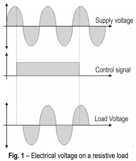 Turning the output ON and OFF only on the mains voltage zero crossing brings important performance advantages to the system: practically no EMI is generated during the load switching and the SSR is submitted to less severe switching conditions. On the other hand, the SSR is suitable for AC loads only (it cannot be used to switch DC loads).
The SSR control signal is indicated by a LED on the SSR body.
ELECTRICAL CONNECTIONS
The two connections needed for the installation of the SSR are the command signal and the load circuit. The load circuit must be protected by an ultra-fast fuse with a rate that matches the SSR nominal current specification. The SSR terminals must be firmly screwed and the wire gauge compatible with the output load.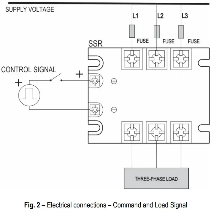
HEAT DISSIPATION
The SSR generates heat during its conduction. This heat must be dissipated to avoid SSR failure due to over-heat. The nominal SSR load specification assumes the use of a suitable heat sink. Without a heat sink, the allowed load current is substantially reduced. The user may calculate the needed heat sink or make use of a heat sink suggested by NOVUS.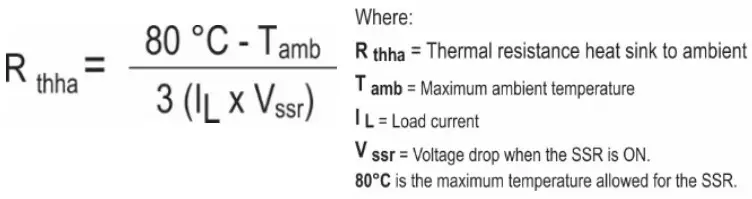 For better heat transfer, a thermal conducting paste must be used between the SSR and the heat sink. The SSR along with its heat sink must be mounted in a vertical position such as to allow for airflow and thus a good heat exchange.
Notes:
- The use of the Thermal Pad that comes with the SSR is optional. In installations where a heat sink is provided for the cooling function, you do not need to use the Thermal Pad. In installations where the surface that will receive the SSR is not perfectly flat, its use may improve the cooling of the SSR.
- Make sure that the screws on the SSR terminals are properly tightened. Contact problems at these points influence the proper operation of the entire installation power system.
- Before continuous use, always perform installation validation tests.
The graphs below show the current carrying capacity of the SSR as a function of ambient temperature when mounted on the indicated heatsink and whether or not the fan is used.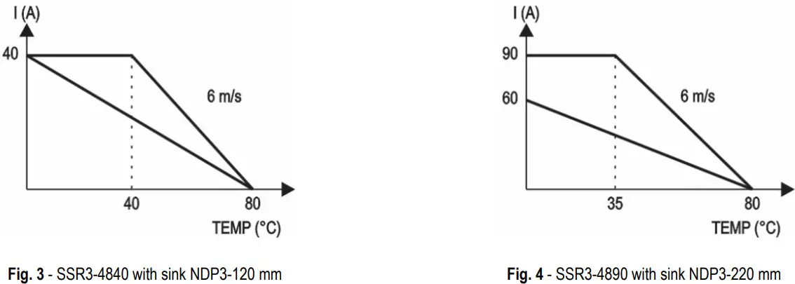 The indicated Novus heatsink models are:
- SSR3-4840: NDP3-120 mm / (P/N 8825000100)
Rthha= 0.52 °C/W
Rthha= 0.175 °C/W (with fan 6 m/s) - SSR3-4890: NDP3-220 mm / (P/N 8825000220)
Rthha= 0.35 °C/W
Rthha= 0.125 °C/W (with fan 6 m/s)
The respective specifications of use are: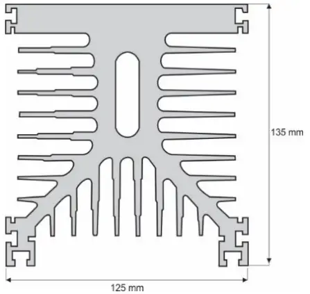
SPECIFICATIONS
| Parameter | Unit | Model | |
| SSR3-4840 | SSR3-4890 | ||
| Load current (IL) | A rms | 40 | 90 |
| Load voltage | V rms | 40 to 530 | 40 to 530 |
| Turn-on voltage (Vssr) | V rms | < 1.5 | < 1.5 |
| Leakage current | mA rms | < 1 | < 1 |
| Frequency | Hz | 47 to 63 | 47 to 63 |
| Dv/dt | V/µs | 300 | 300 |
| Control voltage | Vcc | 4 to 32 | 4 to 32 |
| Control current | mAcc | 15 to 20 | 15 to 20 |
| Switching time | ms | < 10 | < 10 |
| Control method | Zero cross trigger | Zero cross trigger | |
| Isolation | V rms | > 2000 | > 2000 |
| Operating temperature | °C | -40 to 80 | -40 to 80 |
| Weight | g | 397 | 431 |
| Status Indicator | LED | LED | |
Table 1 – Specifications
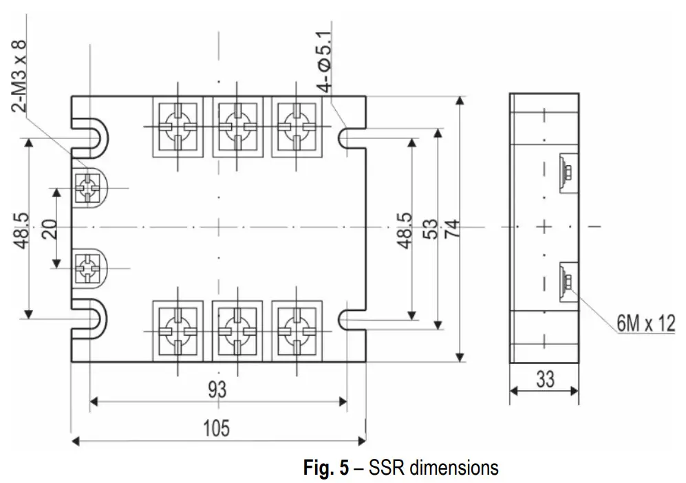
DIMENSIONS
WARRANTY
The warranty conditions are set forth on our website www.novusautomation.com/warranty.
NOVUS AUTOMATION![]()


