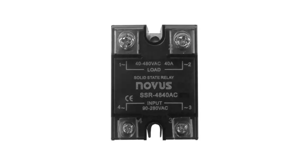
![]() Solid-State Relay – SSR
Solid-State Relay – SSR
SSR 4840AC / 4880AC – INSTRUCTIONS MANUAL – V1.0x D
FEATURES
Solid-State Relays (SSR) are electronic devices used to switch resistive or inductive AC loads with many advantages over conventional relays. A command signal (INPUT) determines the activation of the load connected to the output terminals (OUTPUT) without electrical noise, sparking or mechanical wear.
They have a LED, which acts as an on or off status indicator, internal output snubber, and Zero Crossing function. It turns on at zero Volt and off at zero Ampere. Optical isolation between INPUT and OUTPUT.
OPERATION
Upon receiving a command signal at its input terminals, the SSR conducts (turns on) and powers the load. When the mains voltage crosses zero, conduction takes place. The same process happens during shutdown. The command signal is removed, but the SSR only blocks (turns off) at the next zero crossing.
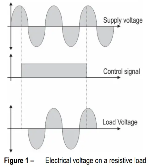
This implies delays of no more than 8.3 milliseconds between the instant the ON/OFF command is triggered and the act of energizing or not energizing the load.
Switching the load power on and off at a zero crossing has important advantages for the installation. No electrical interference is generated in the installation and the SSR is not subjected to severe switching conditions.
It is impossible to switch direct current (DC), only alternating current (AC).
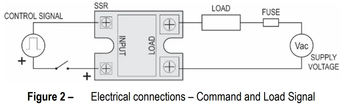
ELECTRICAL CONNECTIONS
2 connections are required: Command signal and connection with the load. When making the connection to the load, you must use an ultra-fast fuse to protect the installation. Well-fixed terminals and adequate wiring help improve the installation efficiency.
HEAT DISSIPATION
SSR generates heat during its conduction. This heat must be dissipated to avoid SSR fail due to over-heat.
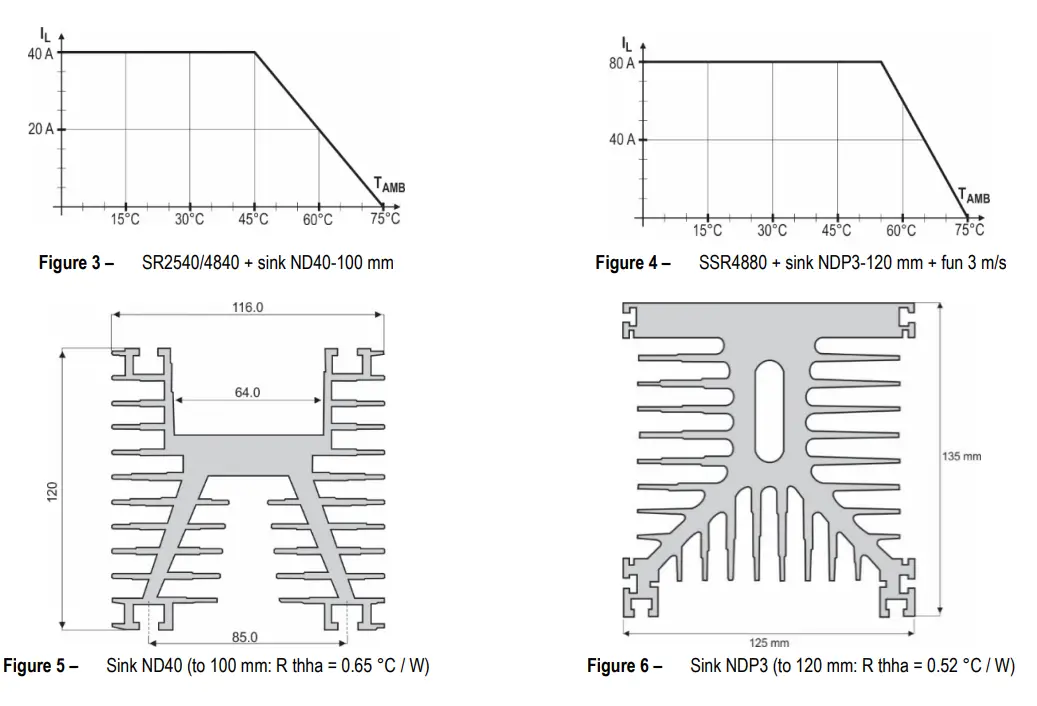
The load current (IL) ratings set for each SSR model consider the use of a suitable heat sink. Without a heat sink, the maximum allowed load current is substantially reduced. You can calculate the appropriate heat sink for your process or use the model indicated by NOVUS.
Where: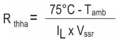 R thha = Thermal resistance heat sink to ambient
T amb = Maximum ambient temperature
IL= Load current
V ssr = Voltage drop when the SSR is ON.
75°C is the maximum temperature allowed for the
t these current levels, in addition to the heat sink, forced ventilation is also critical for maximum performance. Thermal paste, which is essential for perfect heat transfer, must be used between the SSR and the heat sink. The set SSR + heat sink should be fixed in a vertical position to facilitate heat exchange.
Notes:
- The use of the Thermal Pad that comes with the SSR is optional. In installations where a heat sink is provided for the cooling function, you do not need to use the Thermal Pad. In installations where the surface to receive the SSR is not perfectly flat, its use may improve the cooling of the SSR.
- Make sure that the screws on the SSR terminals are properly tightened. Contact problems at these points influence the proper operation of the entire installation power system.
- Before continuous use, always perform installation validation tests.
The graphs below show the current carrying capacity of the SSR as a function of ambient temperature when mounted on the indicated heatsink and whether or not the fan is used.
SPECIFICATIONS
| Parameter | Unit | Model | |
| SSR 4840AC | SSR 4880AC | ||
| Load current (IL) | A rms | 40 | 80 |
| Load voltage | V rms | 40 to 530 | 40 to 530 |
| Voltage drop (Vssr) | V rms | 1.1 to 1.5 | 1.1 to 1.5 |
| Leakage current | mA rms | < 8 | < 8 |
| Frequency | Hz | 47 to 63 | 47 to 63 |
| Dv/dt | V/ps | 500 | 500 |
| 12t (50/60 Hz) | Ms | 1770 / 1629 | 3230 / 2971 |
| Control voltage | V rms | 90 to 280 | 90 to 280 |
| Control current | mA | 5to 10 | 7 to 12 |
| Switching time | ms | < 10 | < 10 |
| Control method | Zero cross trigger (resistive load) Instantaneous (inductive load) | Zero cross trigger (resistive load) Instantaneous (inductive load) | |
| Isolation | V rms | 4000 | 4000 |
| Housing temperature | °C | -40 to 80 | -40 to 80 |
| Plastic body material | UL E211125 / 94 V-0 | ||
| Metal base material | Aluminium with phosphor bronze coating | ||
| Certification | CE | ||
Table 1 – Specifications
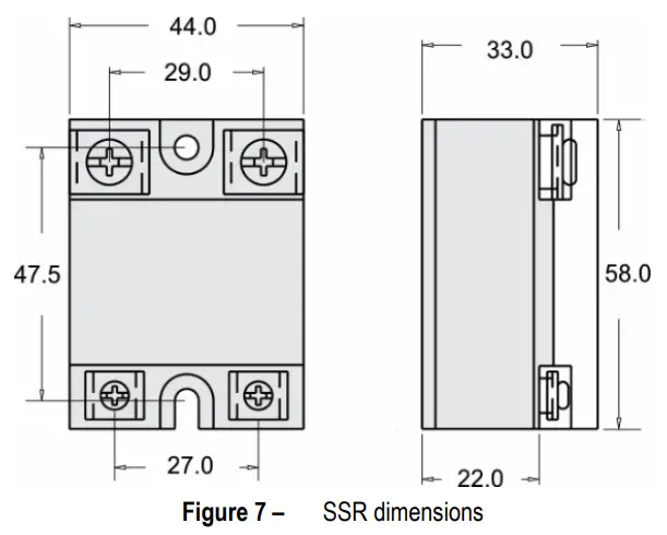
DIMENSIONS
WARRANTY
Warranty conditions are available on our website www.novusautomation.com/warranty.
NOVUS AUTOMATION
![]()


