
VENTS A21 Wireless Control System
CONTROLLER WIRING DIAGRAM
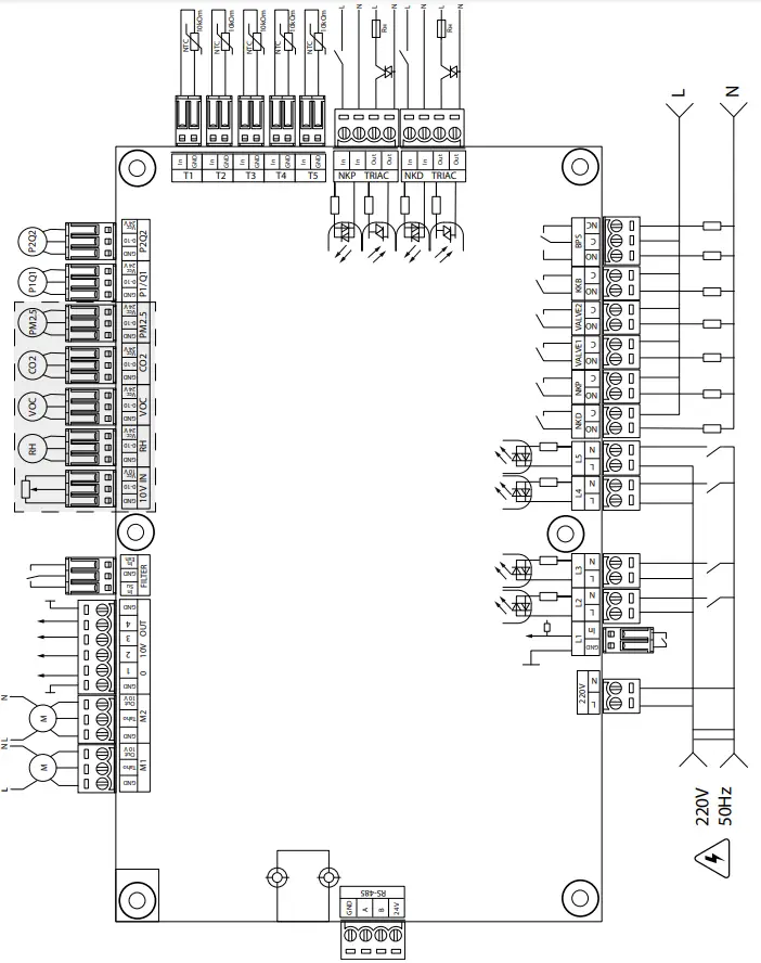
Controller power supply: 100-250 V, 50 (60) Hz, maximum power consumption – 30 W.
Controller inputs
| Input purpose | Input type | Signal type | Designation | Operation logic | Comments |
| Outdoor air temperature | Analogue | NTC 10 kOm | T1 | -40…120 °C | |
| Supply air temperature or temperature downstream of the main air heater | Analogue | NTC 10 kOm | T2 | -40…120 °C | |
| Extract air temperature | Analogue | NTC 10 kOm | T3 | -40…120 °C | |
| Extract air temperature | Analogue | NTC 10 kOm | T4 | -40…120 °C | |
| Return heat medium temperature | Analogue | NTC 10 kOm | T5 | -40…120 °C | |
| External set point adjuster | Analogue | 0-10 V | 10 V IN | Enables fan speed control by means of a potentiometer. This input is enabled/disabled via the Engineering Menu (sensors). The terminal is energised with 10 V. | |
| Main humidity sensor | Analogue | 0-10 V | RH | Each of the sensors is enabled/disabled via the Engineering menu. The sensors are energised with 24 V for powering external sensors. The power supply overload protection is triggered by a short circuit or a total current on the 24 V line in excess of 700 mA. Once the overload protection is activated, the power is restored only after a manual reset at the power supply unit. | |
| Main VOC sensor | Analogue | 0-10 V | VOC | ||
| Main CO2 sensor | Analogue | 0-10 V | CO2 | ||
| Main PM2.5 sensor | Analogue | 0-10 V | PM2.5 | ||
| Supply fan control | Discrete | Open collector/ dry contact | M1 (TACHO) | NC | The control feature can be configured to fan tach pulses or an external dry contact, or disabled. You can also program the number of tach pulses per fan revolution and the alarm condition detection time. |
| Exhaust fan control | Discrete | Open collector/ dry contact | M2 (TACHO) | NC | |
| Supply filter contamination control | Discrete | Dry contact | FILTER (IN SU) | NO | |
| Extract filter contamination control | Discrete | Dry contact | FILTER (IN EXH) | NO | |
| Heat medium flow control | Discrete | Dry contact | L1 | NC | This input is enabled/disabled via the Engineering Menu. |
| Heat medium pressure control | Discrete | ~220 V | L2 | NC | This input is enabled/disabled via the Engineering Menu. |
| Fire alarm sensor | Discrete | ~220 V | L3 | NC | This input is enabled/disabled via the Engineering Menu. |
| Boost switch | Discrete | ~220 V | L4 | NO | This input is enabled/disabled via the Engineering Menu. |
| Fireplace switch | Discrete | ~220 V | L5 | NO | This input is enabled/disabled via the Engineering Menu. |
| Electric preheating thermostat (alarm) | Discrete | ~220 V | NKP TRIAC (IN) | NC | |
| Electric reheater thermostat (alarm) or water heater capillary thermostat (alarm) | Discrete | ~220 V | NKD TRIAC (IN) | NC |
Controller outputs
| Output purpose | Output type | Signal type | Designation | Note |
| Supply fan control | Analogue | 0-10 V | M1 (OUT 0-10) | You can configure the minimum and the maximum value of the signal sent to an active fan and the delay before switching to automatic control after activating the unit. |
| Exhaust fan control | Analogue | 0-10 V | M2 (OUT 0-10) | |
| Analogue control of the reheater or water heater valve control | Analogue | 0-10 V | 0-10V OUT (1) | The operation of this output depends on the heater type selected via the Engineering Menu: Electric. The system controls an external circuit board which operates the heater (e.g. multi-stage) Water. 2-10 V valve control signal. |
| Analogue control of the bypass | Analogue | 0-10 V | 0-10V OUT (2) | |
| Analogue control of the cooler | Analogue | 0-10 V | 0-10V OUT (3) | The operation of this output depends on the cooler type selected via the Engineering Menu: Discrete. Output inactive. Analogue. The output will control the built-in or external cooler with its own control circuit. |
| Electric preheater control | External TRIAC control | NKP TRIAC (OUT) | PWM signal is modulated to an external TRIAC with a 10 second cycle. | |
| Electric reheater control | External TRIAC control | NKP TRIAC (OUT) | PWM signal is modulated to an external TRIAC with a 10 second cycle. | |
| Electric preheater release | Relay | 3A, =30 V/~250 V | NKP | |
| Electric heater release or water heater pump release | Relay | 3A, =30 V/~250 V | NKD | |
| Supply damper actuator control and/or supply fan frequency converter release | Relay | 3A, =30 V/~250 V | VALVE1 | |
| Extract damper actuator control and/or exhaust fan frequency converter release | Relay | 3A, =30 V/~250 V | VALVE2 | |
| Discrete control of the cooler | Relay | 3A, =30 V/~250 V | KKB | The operation of this output depends on the cooler type selected via the Engineering Menu: Discrete. The output will directly control the cooler. Analogue. The output will be used for cooler release. You can configure the minimum activation period and the minimum idle time before a subsequent activation. |
| Discrete control of the bypass or analogue control of the rotary heat exchanger | Two relay outputs | 3A, =30 V/~250 V
3A, =30 V/~250 V | BPS | The operation of this output depends on the unit configuration. Discrete bypass: Opening the bypass closes the BPS relay (C – NO) and opens the BPS relay (C – NC). Closing the bypass opens the BPS relay (C – NO) and closes the BPS relay (C – NC). Rotary heat exchanger: Discrete. The output will directly control the actuator. Analogue. The output will be used for actuator release. The BPS relay (C – NO) is enabled. |
Communication interfaces
| RS-485 | The terminal (RS-485) is energised with 24 DC V to power up to 16 external devices. The maximum current is 500 mA. Any current in excess of 500 mA triggers the overload protection to automatically restore power once the load reverts to normal. |
| Wi-Fi | The unit can be fitted with a 50 ohm remote antenna. |
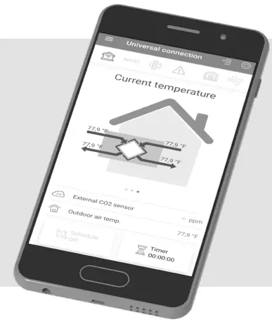
CONNECTING A MOBILE DEVICE TO THE UNIT
The fan is controlled by the Vents Home application on the mobile device. The application is available for download at App Store, Play Market or via the QR code.
| Vents Home – App Store | Vents Home – Play Market |
 | |
Wi-Fi technical data
| Standard | IEFE 802,11, b/g/n |
| Frequency band [GHz] | 2.4 |
| Transmission power [mW] (dBm) | 100(+20) |
| Network | DHCP |
| WLAN safety | WPA, WPA2 |
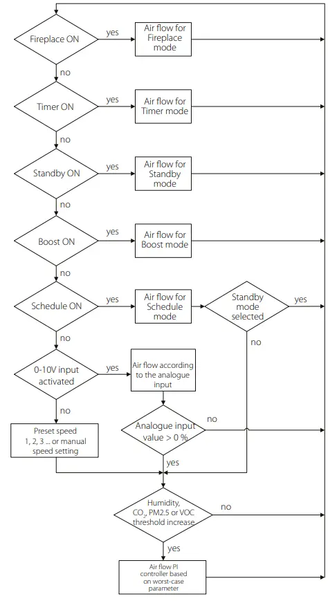
MODE PRIORITIES
ALARM AND WARNING CODES
Description
| 0 | Alarm! Supply fan malfunction. • Determined depending on a specific configuration. • By rpm: if the supply fan speed drops below 300 rpm for 30 seconds (configurable within a 5 to 120 second range). • By discrete input: if the discrete input (ТAНО М1) remains open for 30 seconds (configurable within a 5 to 120 second range) provided that the supply fan must be running. |
| 1 | Alarm! Extract fan malfunction. Determined depending on a specific configuration. • By rpm: if the extract fan speed drops below 300 rpm for 30 seconds (configurable within a 5 to 120 second range). • By discrete input: if the discrete input (ТAНО М2) remains open for 30 seconds (configurable within a 5 to 120 second range) provided that the extract fan must be running. |
| 2 | Alarm! No outdoor air temperature sensor detected. Determined if the heat exchanger freeze protection is active or the unit is configured with a bypass, a rotary heat exchanger, a cooler or a water heater. |
| 3 | Alarm! Short circuit of the outdoor air temperature sensor. Determined if the heat exchanger freeze protection is active or the unit is configured with a bypass, a rotary heat exchanger, a cooler or a water heater. |
| 4 | Alarm! No supply air temperature sensor detected. Determined in any unit configuration. |
| 5 | Alarm! Short circuit of the supply air temperature sensor. Determined in any unit configuration |
| 6 | Alarm! No sensor of the extract air temperature upstream of the heat exchanger detected. Determined if the extract air temperature sensor is selected as the master sensor for temperature control provided that the main heater or condensing unit are enabled. The alarm will also be determined irrespective of which sensor is selected for temperature control if the bypass or rotary heat exchanger is enabled. |
| 7 | Alarm! Short circuit of the extract air temperature sensor. Determined if the extract air temperature sensor is selected as the master sensor for temperature control provided that the main heater or condensing unit are enabled. The alarm will also be determined irrespective of which sensor is selected for temperature control if the bypass or rotary heat exchanger is enabled. |
| 8 | Alarm! No sensor of the exhaust air temperature downstream of the heat exchanger detected. Determined if the heat exchanger freeze protection is active. |
| 9 | Alarm! Short circuit of the exhaust air temperature sensor. Determined if the heat exchanger freeze protection is active. |
| 10 | Alarm! Preheater protective thermostat activated. Determined if the preheater is selected for protecting the heat exchanger from freezing (NKP IN). |
| 11 | Alarm! Main heater protective thermostat activated. Determined if electric or water heater is enabled as the main heater and the discrete input (NKD IN) is open. |
| 12 | Alarm! Preheating cannot provide heat exchanger freezing protection. Determined if the preheater is selected for protecting the heat exchanger from freezing and freezing danger warning has been active for 30 minutes. |
| 13 | Warning! Main humidity sensor not detected. Determined if the main humidity sensor is activated and its signal value is 0. |
| 14 | Warning! Main CO₂ sensor not detected. Determined if the main CO₂ sensor is activated and its signal value is 0. |
| 15 | Warning! Main PM2.5 sensor not detected. Determined if the main PM2.5 sensor is activated and its signal value is 0. |
| 16 | Warning! Main VOC sensor not detected. Determined if the main VOC sensor is activated and its signal value is 0. |
| 17 | Warning! External humidity sensor not detected. Determined if the sensor has sent no feedback to the controller for 20 seconds while being active. |
| 18 | Warning! External CO₂ sensor not detected. Determined if the sensor has sent no feedback to the controller for 20 seconds while being active. |
| 19 | Warning! External PM2.5 sensor not detected. Determined if the sensor has sent no feedback to the controller for 20 seconds while being active. |
| 20. | Warning! External VOC sensor not detected. Determined if the sensor has sent no feedback to the controller for 20 seconds while being active. |
| 21 | Warning! Indoor air temperature not detected! The air temperature is controlled by using the feedback from the temperature sensor in the supply air duct downstream of the heat exchanger. Determined if no sensor data has been communicated from the control panel to the controller for 20 seconds if the sensor is selected as the temperature control master sensor provided that the main heater, the bypass, the rotary heat exchanger or the condensing unit are enabled. |
| 22 | Warning! Heat exchanger freezing danger. Determined if the supply fan is enabled, the outdoor temperature drops below -3 ˚С and remains below -1 ˚С, and the exhaust air temperature downstream of the heat exchanger drops below 2 ˚С and remains below 3 ˚С. |
| 23 | Warning! The battery is low. The weekly schedule function will work incorrectly. Determined if no battery is detected or its voltage level drops below 2 V. The battery voltage level is monitored every 5 minutes. |
| 24 | Warning! Replace the supply air filter. Determined if the pressure switch is triggered closing the discrete input (FILTER IN SU). |
| 25 | Alarm! Fire alarm activated. Determined if the fire alarm sensor is triggered opening the discrete input (L3). This alarm causes the fans to shut down immediately overriding any prior electric heater blowing commands. |
| 26 | Alarm! Low supply air temperature. Determined if the minimum supply air temperature control function is enabled (the default setpoint is +10 °С configurable within a +5 °С to +12 °С range), and the supply air temperature remains below the control setpoint for 10 minutes with the condensing unit disabled and the bypass closed. |
| 27 | Alarm! Return water temperature sensor not detected. Determined if the water heater is enabled as the main heater. |
| 28 | Alarm! Short circuit of the return water temperature sensor. Determined if the water heater is enabled as the main heater. |
| 29 | Warning! Replace the extract air filter. Determined if the pressure switch is triggered closing the discrete input (FILTER IN EXH). |
| 30 | Alarm! No water pressure detected. Determined if no water pressure is detected provided that the water heater and the water pressure sensor are enabled. |
| 31 | Alarm! No water flow detected. Determined if no water flow is detected provided that the water heater and the water flow sensor are enabled. |
| 32 | Alarm! Low return water temperature. |
| 33 | Alarm! Supply fan cannot provide heat exchanger freezing protection. Determined if the supply fan is selected for protecting the heat exchanger from freezing and the freezing danger warning has been active for 30 minutes. |
| 34 | Alarm! Bypass cannot provide heat exchanger freezing protection. Determined if the bypass is selected for protecting the heat exchanger from freezing and the freezing danger warning has been active for 30 minutes. |
| 35 | Warning! Freeze protection disabled. This may cause heat exchanger freezing! Determined if the rotary heat exchanger is not enabled and the freeze protection is deactivated. |
| 36 | Warning! The main heater is operated in the manual mode. |
| 37 | Warning! The cooler is operated in the manual mode. |
| 38 | Warning! The bypass is operated in the manual mode. |
| 39 | Warning! The rotary heat exchanger is operated in manual mode. |
| 40 | Warning! The filter timer countdown is completed. Please, replace the filter. |
| 41 | Warning! Incorrect operation of the rotary heat exchanger. |
| 42 | Warning! Preheater is operated in the manual mode. |
| 43 | Alarm! Return water temperature failed to reach setpoint in due time before AHU start. |
| 44 | Warning! The selected type of freeze protection of the heat exchanger by means of the bypass is replaced by freeze protection by means of the supply fan as the main heater operation is not allowed. |
| 45 | Warning! The fireplace mode is locked. This mode is not compatible with the selected type of freeze protection of the heat exchanger. |


