VENTS V37EN Water Duct Heater
Introduction
The present operation manual is combined with technical specification, operating instruction, certificate, information on installation. Device: Water duct heater NKV of VENTS series (further in the text “NKV”)
Function
Device NKV with water as heat carrier and round or rectangular connection to the air duct is designed for heating of air in the air-conditioning, ventilation and hot-air heating systems and in drying units and warm air curtains.
Delivery set contains:
- device NKV – 1 piece
- operation manual – 1 piece
- packing box – 1 piece.
Technical specifications
NKV devices are used in enclosed spaces at ambient air temperatures from +1°C to +50°C. Maximum temperature: 100°C, maximum pressure at 100°C : 1.6 MPa (16 bar). NKVs are designed for exploitation in area with moderate and cold climate (UHL 3 by GOST 15150-69).
Symbolic representation of the device
- For rectangular ducts:

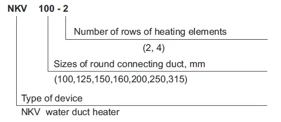
- For round ducts:

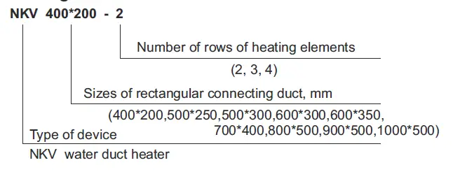
Examples:
NKV 400*200-2 – water duct heater for connecting to rectangular ducts of 400*200mm with two rows of heating elements.
NKV 100-4 – water duct heater for connecting to round ducts of 100mm with four rows of heating elements.
Design and principle of operation
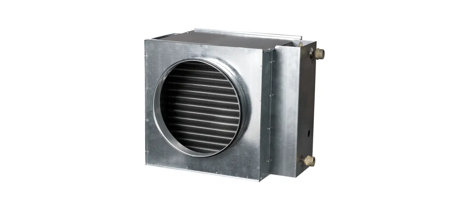
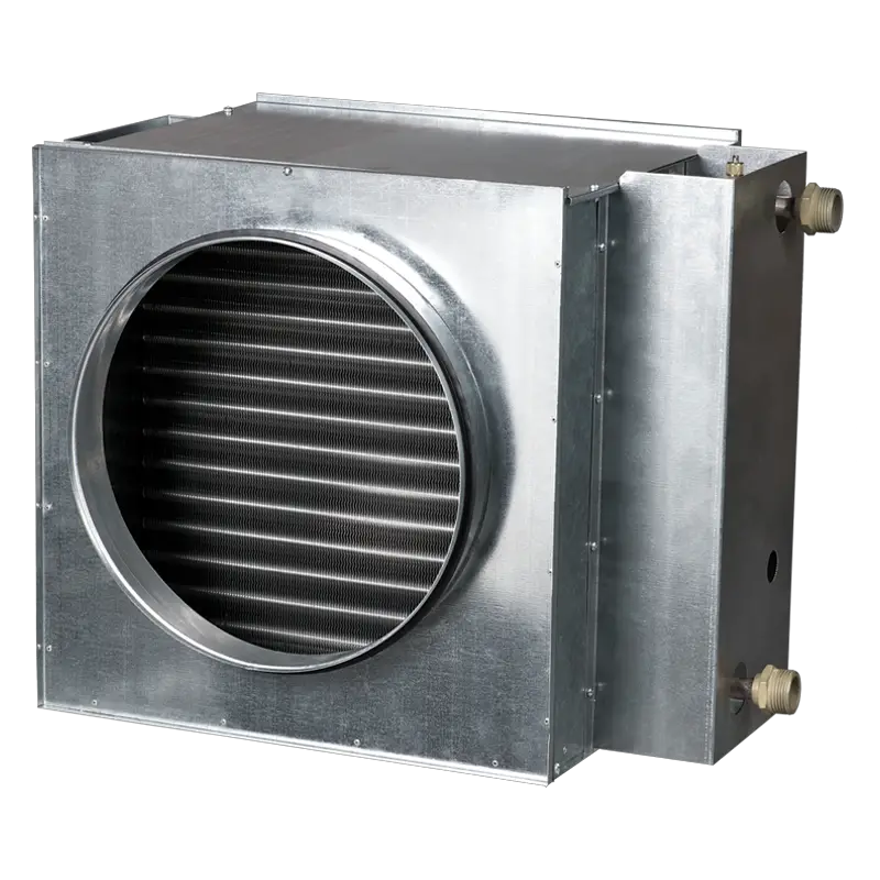
- Design of NKV with rectangular and round connecting to air duct
(Picture 1 and Picture 2) consists of the case (1) and the heating element (3) built-in the case. The case consists of the wall
(6 for round ducts), two protective casings (2) manufactured from high-quality galvanized steel. - A heating block is a package of two or four rows of copper tubes with aluminum ribs set on them and copper unions. The tubes are joined in groups the ends of which soldered in manifolds made from copper pipes through which the heat carrier goes in and out.
- For connecting to the external system the manifolds have special unions on the butt end of the heating block providing the threaded connection. The output manifold has a nipple with thread (G1/4) with a plug (place Л on Picture 1 and Picture 2 ), instead of which an immersion sensor may be placed for measuring the temperature or for protection from freezing. There is also an air-relief nipple with thread G1/2 (4), a water-drain nipple with thread G1/2 (5) from the butt end of NKV.
- The air is heated during its passage through the heat exchanger in the process of interaction with copper tubes and aluminum plates. All heaters are tested for leak tightness at a maximum working pressure of 1.6 MPa and water temperature of 100°C. Connection dimensions correspond to connection dimensions of elements of duct ventilation (duct fans, electric duct heaters, duct noise mufflers, etc.)
- For NKV a surface-mount sensor is possible to apply instead of an immersion sensor.
- Water heaters are supplied without temperature sensors and frost protection. To avoid emergency situations during the exploitation of NKV, please provide the water flow excluding the possibility of freezing of NKV.
Basic parameters and dimensions
Basic dimensions of NKV with round and rectangular connecting to the air duct must correspond to the values listed in tables 1, 2 and on Picture 1 and Picture 2. Basic parameters and technical specifications are listed in tables 3, 4.
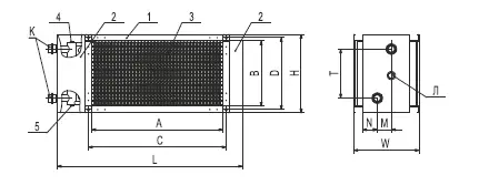
Picture 1: Basic dimensions of NKV with rectangular connecting to the air duct 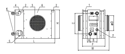
Picture 2: Basic dimensions of NKV with connecting to round air duct
| Type | А | B | C | D | L | H | W | N | M | T | K | Number of rows of pipes | Weight, kg |
| NKV 400*200-2 | 400 | 200 | 420 | 220 | 565 | 240 | 200 | 43 | 43 | 150 | G 3/4” | 2 | 7,6 |
| NKV 400*200-4 | 400 | 200 | 420 | 220 | 565 | 240 | 200 | 38 | 65 | 150 | G 3/4” | 4 | 8,1 |
| NKV 500*250-2 | 500 | 250 | 520 | 270 | 665 | 290 | 200 | 43 | 43 | 200 | G 3/4” | 2 | 15,8 |
| NKV 500*250-4 | 500 | 250 | 520 | 270 | 665 | 290 | 200 | 38 | 65 | 200 | G 3/4” | 4 | 16,3 |
| NKV 500*300-2 | 500 | 300 | 520 | 320 | 665 | 340 | 200 | 43 | 43 | 250 | G 1” | 2 | 11,5 |
| NKV 500*300-4 | 500 | 300 | 520 | 320 | 665 | 340 | 200 | 38 | 65 | 250 | G 1” | 4 | 12,0 |
| NKV 600*300-2 | 600 | 300 | 620 | 320 | 765 | 340 | 200 | 43 | 43 | 250 | G 1” | 2 | 21,8 |
| NKV 600*300-4 | 600 | 300 | 620 | 320 | 765 | 340 | 200 | 38 | 65 | 250 | G 1” | 4 | 22,3 |
| NKV 600*350-2 | 600 | 350 | 620 | 370 | 765 | 390 | 200 | 43 | 43 | 300 | G 1” | 2 | 22,4 |
| NKV 600*350-4 | 600 | 350 | 620 | 370 | 765 | 390 | 200 | 38 | 65 | 300 | G 1” | 4 | 22,9 |
| NKV 700*400-2 | 700 | 400 | 720 | 420 | 865 | 440 | 200 | 36 | 47 | 350 | G 1” | 2 | 27,8 |
| NKV 700*400-3 | 700 | 400 | 720 | 420 | 865 | 440 | 200 | 42 | 58 | 350 | G 1” | 3 | 28,4 |
| NKV 800*500-2 | 800 | 500 | 820 | 520 | 965 | 540 | 200 | 36 | 47 | 450 | G 1” | 2 | 36,5 |
| NKV 800*500-3 | 800 | 500 | 820 | 520 | 965 | 540 | 200 | 42 | 58 | 450 | G 1” | 3 | 37,2 |
| NKV 900*500-2 | 900 | 500 | 920 | 520 | 1065 | 540 | 200 | 36 | 47 | 450 | G 1” | 2 | 40,4 |
| NKV 900*500-3 | 900 | 500 | 920 | 520 | 1065 | 540 | 200 | 42 | 58 | 450 | G 1” | 3 | 41,2 |
| NKV 1000*500-2 | 1000 | 500 | 1020 | 520 | 1165 | 540 | 200 | 36 | 47 | 450 | G 1” | 2 | 44,3 |
| NKV 1000*500-3 | 1000 | 500 | 1020 | 520 | 1165 | 540 | 200 | 42 | 58 | 450 | G 1” | 3 | 45,2 |
Table 2: Basic dimensions of NKV with round connecting to the air duct
| Type | D | L | H | W | F | A | B | C | K | Number of rows of pipes | Weight, kg |
| NKV 100-2 | 99 | 350 | 230 | 300 | 220 | 32 | 43 | 150 | G 3/4” | 2 | 4,5 |
| NKV 100-4 | 99 | 350 | 230 | 300 | 220 | 28 | 65 | 150 | G 3/4” | 4 | 5,2 |
| NKV 125-2 | 124 | 350 | 230 | 300 | 220 | 32 | 43 | 150 | G 3/4” | 2 | 4,5 |
| NKV 125-4 | 124 | 350 | 230 | 300 | 220 | 28 | 65 | 150 | G 3/4” | 4 | 5,2 |
| NKV 150-2 | 149 | 400 | 280 | 300 | 220 | 32 | 43 | 200 | G 3/4” | 2 | 7,5 |
| NKV 150-4 | 149 | 400 | 280 | 300 | 220 | 28 | 65 | 200 | G 3/4” | 4 | 8,2 |
| NKV 160-2 | 159 | 400 | 280 | 300 | 220 | 32 | 43 | 200 | G 3/4” | 2 | 7,5 |
| NKV 160-4 | 159 | 400 | 280 | 300 | 220 | 28 | 65 | 200 | G 3/4” | 4 | 8,2 |
| NKV 200-2 | 198 | 400 | 280 | 300 | 220 | 32 | 43 | 200 | G 3/4” | 2 | 7,5 |
| NKV 200-4 | 198 | 400 | 280 | 300 | 220 | 28 | 65 | 200 | G 3/4” | 4 | 8,2 |
| NKV 250-2 | 248 | 470 | 350 | 350 | 270 | 32 | 43 | 270 | G 1” | 2 | 10,3 |
| NKV 250-4 | 248 | 470 | 350 | 350 | 270 | 28 | 65 | 270 | G 1” | 4 | 10,8 |
| NKV 315-2 | 313 | 550 | 430 | 450 | 370 | 57 | 43 | 350 | G 1” | 2 | 11,5 |
| NKV 315-4 | 313 | 550 | 430 | 450 | 370 | 53 | 65 | 350 | G 1” | 4 | 12,2 |
Table 3: Basic technical specifications of NKV with rectangular connecting to the air duct for two-row, three-row and four-row execution.
|
Type | Air flow, m3/h | Differential pressure, Pa | Inlet air, °С | Water temperature, °С (inlet/outlet) 80/60 | |||
| Inlet air, °С | Capacity of heater, kW | Water consump- tion, l/s | Water pressure drop, KPa | ||||
| NKV 400*200-2 | 1100 | 62 | -5 | 19 | 10 | 0,12 | 2 |
| 0 | 23 | 9,2 | 0,12 | 2 | |||
| 5 | 26 | 8,5 | 0,11 | 2 | |||
| 10 | 29 | 8,0 | 0,10 | 1 | |||
| NKV 400*200-4 | 1100 | 125 | -5 | 35 | 17 | 0,21 | 1 |
| 0 | 37 | 15 | 0,19 | 1 | |||
| 5 | 39 | 14 | 0,17 | 1 | |||
| 10 | 4,5 | 12 | 0,15 | 1 | |||
| NKV 500*250-2 | 1850 | 62 | -5 | 20,5 | 17 | 0,20 | 6,5 |
| 0 | 24 | 15,3 | 0,18 | 6,5 | |||
| 5 | 27,5 | 14,5 | 0,17 | 4,5 | |||
| 10 | 31 | 13 | 0,15 | 3,5 | |||
| NKV 500*250-4 | 1850 | 125 | -5 | 38 | 28 | 0,34 | 6,1 |
| 0 | 40 | 26 | 0,32 | 5,1 | |||
| 5 | 42,6 | 24 | 0,30 | 5 | |||
| 10 | 42,5 | 22,1 | 0,27 | 4 | |||
| NKV 500*300-2 | 2350 | 62 | -5 | 19 | 20 | 0,24 | 3 |
| 0 | 21 | 18 | 0,22 | 2 | |||
| 5 | 25 | 16 | 0,21 | 2 | |||
| 10 | 28 | 15 | 0,19 | 2 | |||
| NKV 500*300-4 | 2350 | 125 | -5 | 37 | 34 | 0,42 | 5 |
| 0 | 39 | 31 | 0,40 | 4 | |||
| 5 | 41 | 29 | 0,36 | 4 | |||
| 10 | 43 | 26 | 0,32 | 3 | |||
| NKV 600*300-2 | 3000 | 62 | -5 | 18 | 24 | 0,3 | 4 |
| 0 | 20 | 22 | 0,28 | 3 | |||
| 5 | 24 | 20 | 0,25 | 3 | |||
| 10 | 27 | 18 | 0,23 | 3 | |||
| NKV 600*300-4 | 3000 | 125 | -5 | 37 | 42 | 0,51 | 9 |
| 0 | 41 | 38 | 0,47 | 8 | |||
| 5 | 42 | 35 | 0,43 | 7 | |||
| 10 | 45 | 32 | 0,4 | 6 | |||
| NKV 600*350-2 | 3400 | 62 | -5 | 19 | 28 | 0,35 | 4 |
| 0 | 20,5 | 26 | 0,32 | 4 | |||
| 5 | 24 | 24 | 0,29 | 3 | |||
| 10 | 27 | 22 | 0,27 | 3 | |||
| NKV 600*350-4 | 3400 | 125 | -5 | 37 | 49 | 0,6 | 10 |
| 0 | 39 | 45 | 0,55 | 8 | |||
| 5 | 41 | 41 | 0,51 | 7 | |||
| 10 | 43 | 37 | 0,46 | 6 | |||
| NKV 700*400-2 | 4600 | 113 | -5 | 21,8 | 45,3 | 0,56 | 4,1 |
| 0 | 25,2 | 41,8 | 0,5 | 3,6 | |||
| 5 | 28,5 | 38,2 | 0,47 | 3 | |||
| 10 | 31,9 | 34,6 | 0,43 | 2,6 | |||
| NKV 700*400-3 | 4600 | 170 | -5 | 33 | 64,2 | 0,78 | 10,9 |
| 0 | 35,8 | 59,3 | 0,72 | 9,4 | |||
| 5 | 38,4 | 54,4 | 0,67 | 8,1 | |||
| 10 | 41 | 49,6 | 0,62 | 6,8 | |||
| NKV 800*500-2 | 6800 | 128 | -5 | 20,5 | 63,7 | 0,78 | 4,4 |
| 0 | 23,9 | 58,7 | 0,72 | 3,9 | |||
| 5 | 27,3 | 53,6 | 0,67 | 3,2 | |||
| 10 | 30,7 | 48,5 | 0,62 | 2,6 | |||
| NKV 800*500-3 | 6800 | 193 | -5 | 29,7 | 86,7 | 1,05 | 5,6 |
| 0 | 32,5 | 79,8 | 0,97 | 4,8 | |||
| 5 | 35,3 | 72,9 | 0,89 | 4 | |||
| 10 | 38,2 | 65,8 | 0,81 | 3,2 | |||
| NKV 900*500-2 | 7300 | 120 | -5 | 21,5 | 70,2 | 0,86 | 5,7 |
| 0 | 24,8 | 64,5 | 0,81 | 5,1 | |||
| 5 | 28,2 | 59,8 | 0,73 | 4,2 | |||
| 10 | 32,2 | 54,2 | 0,67 | 3,7 | |||
| NKV 900*500-3 | 7300 | 180 | -5 | 30,5 | 96,5 | 1,18 | 7,2 |
| 0 | 33,7 | 88,9 | 1,07 | 6,1 | |||
| 5 | 36,4 | 81,2 | 0,99 | 5,2 | |||
| 10 | 39,5 | 73,5 | 0,85 | 4,3 | |||
| NKV 1000*500-2 | 7800 | 111 | -5 | 22,4 | 78,4 | 0,94 | 7,1 |
| 0 | 25,7 | 72,3 | 0,89 | 6,1 | |||
| 5 | 29 | 66,2 | 0,8 | 5,2 | |||
| 10 | 33,6 | 60,1 | 0,71 | 4,8 | |||
| НКВ 1000*500-3 | 7800 | 167 | -5 | 32 | 106,1 | 1,3 | 8,7 |
| 0 | 34,8 | 97,8 | 1,19 | 7,5 | |||
| 5 | 37,4 | 89,5 | 1,1 | 6,4 | |||
| 10 | 40,8 | 81,3 | 0,9 | 5,3 | |||
|
Type |
Air flow, m3/h | Differential pressure, Pa |
Inlet air, °С | Water temperature, °С (inlet/outlet) 80/60 | |||
| Inlet air, °С | Capacity of heater, kW | Water consump- tion, l/s | Water pressure drop, KPa | ||||
| NKV 100-2 | 150 | 20 | -5 | 21,6 | 1,6 | 0,02 | 1 |
| 0 | 25,9 | 1,4 | 0,02 | 1 | |||
| 5 | 30,2 | 1,2 | 0,01 | 0,5 | |||
| 10 | 34 | 1,0 | 0,01 | 0,5 | |||
| NKV 100-4 | 150 | 31 | -5 | 36 | 2,3 | 0,03 | 2 |
| 0 | 39 | 2,03 | 0,02 | 2 | |||
| 5 | 42 | 1,75 | 0,02 | 2 | |||
| 10 | 45 | 1,5 | 0,02 | 1 | |||
| NKV 125-2 | 215 | 15 | -5 | 18,4 | 2 | 0,03 | 1 |
| 0 | 22,8 | 1,8 | 0,02 | 1 | |||
| 5 | 27,3 | 1,5 | 0,02 | 1 | |||
| 10 | 31,8 | 1,2 | 0,02 | 1 | |||
| NKV 125-4 | 215 | 40 | -5 | 43 | 4,8 | 0,06 | 10 |
| 0 | 46 | 4,3 | 0,06 | 9 | |||
| 5 | 48 | 3,8 | 0,05 | 8 | |||
| 10 | 51 | 3,4 | 0,05 | 6 | |||
| NKV 150-2 | 320 | 28 | -5 | 24 | 4,1 | 0,05 | 8 |
| 0 | 26 | 3,8 | 0,05 | 6 | |||
| 5 | 30,5 | 3,6 | 0,04 | 5 | |||
| 10 | 35 | 3,0 | 0,04 | 4 | |||
| NKV 150-4 | 320 | 41 | -5 | 36 | 6,05 | 0,06 | 15 |
| 0 | 40 | 5,4 | 0,06 | 14 | |||
| 5 | 42 | 5,0 | 0,06 | 13 | |||
| 10 | 46 | 4,3 | 0,05 | 11 | |||
| NKV 160-2 | 400 | 31 | -5 | 26,1 | 4,4 | 0,05 | 9 |
| 0 | 30,8 | 4,0 | 0,05 | 7 | |||
| 5 | 35,3 | 3,5 | 0,04 | 6 | |||
| 10 | 39 | 3,0 | 0,04 | 4 | |||
| NKV 160-4 | 400 | 42 | -5 | 38 | 6,5 | 0,07 | 16 |
| 0 | 42 | 5,6 | 0,07 | 15 | |||
| 5 | 45,5 | 5,2 | 0,06 | 14 | |||
| 10 | 48,3 | 4,5 | 0,06 | 12 | |||
| NKV 200-2 | 600 | 23 | -5 | 20,6 | 5,9 | 0,07 | 13 |
| 0 | 26,0 | 5,2 | 0,06 | 10 | |||
| 5 | 31,0 | 4,6 | 0,06 | 8 | |||
| 10 | 35,8 | 4,0 | 0,05 | 7 | |||
| NKV 200-4 | 600 | 44 | -5 | 36,8 | 11 | 0,13 | 13 |
| 0 | 40,5 | 9,8 | 0,12 | 11 | |||
| 5 | 43,6 | 8,7 | 0,11 | 9 | |||
| 10 | 47,2 | 7,8 | 0,09 | 7 | |||
| NKV 250-2 | 900 | 25 | -5 | 22,3 | 9,9 | 0,12 | 7 |
| 0 | 27,1 | 8,9 | 0,11 | 6 | |||
| 5 | 31,9 | 7,7 | 0,09 | 5 | |||
| 10 | 36,6 | 6,7 | 0,08 | 4 | |||
| NKV 250-4 | 900 | 39 | -5 | 40,4 | 16 | 0,2 | 12 |
| 0 | 43 | 14 | 0,17 | 9 | |||
| 5 | 47 | 12 | 0,15 | 8 | |||
| 10 | 49 | 10,5 | 0,13 | 6 | |||
| NKV 315-2 | 1420 | 27 | -5 | 27 | 18 | 0,22 | 9 |
| 0 | 32 | 16,3 | 0,2 | 8 | |||
| 5 | 36,9 | 14,5 | 0,18 | 6 | |||
| 10 | 41,2 | 12,9 | 0,16 | 5 | |||
| NKV 315-4 | 1420 | 37 | -5 | 39,6 | 24 | 0,3 | 15 |
| 0 | 43,2 | 21,9 | 0,27 | 12 | |||
| 5 | 46,5 | 19 | 0,24 | 10 | |||
| 10 | 49,8 | 16,8 | 0,2 | 8 | |||
Safety requirements
Requirements of the present operation manual, Rules of safe operation of consumer’s electric devices, current building norms and rules, Rules of fire safety in Ukraine shall be observed during installation and operation of NKV. Before starting the NKV please make sure there are no visible damage of the device, no foreign objects in the duct or leaks in the joins.
Connection of NKV shall be carried out by a qualified worker who has admittance to such works. The heated air shall not contain any solid, fiber, adhesive, or aggressive admixtures that may cause aluminum, copper and zinc corrosion. The maximum permissible water temperature is +100°C. The maximum permissible pressure is 1.6 MPa. The working pressure of the heating water is 0.8 MPa. If water is used as heat carrier, an NKV shall be mounted only inside the room with a maintained constant temperature not going down to the freezing point. External mounting is possible only if n case if a nonfreezing mixture is used as a heat carrier.
Warning! Do not use an NKV for work with explosive dust air mixture.
Warning! Damage of copper pipes (deformation and breakup) may occur in the heat exchanger at the freezing of water. As a result, leakage of water from the heat exchanger circuit will occur and the heater will be out of order. The exploitation of the device beyond the temperature range specified in the operation manual and in rooms with the air containing aggressive admixtures is forbidden.
Installation
- Installed directly in the air ducts in the positions that make it possible to join connecting pipes in horizontally, from the side of an NKV or vertically from above.
- The connection of pipes vertically from below is impermissible. The water duct heater may be of right or left executions depending on the customer’s request. When water is used as the heat carrier, the heaters shall be used in rooms where the temperature is above 0°C.
- The heater shall be installed in the air ducts of similar diameter (size). The operating position of the heater shall ensure free access for service maintenance, for the joining of pipes with the heat carrier.
- It is recommended to install the air filter in front of an NKV in the direction of airflow.
- A water heater may be installed in front of or behind the fan.
- If a NKV is placed in front of a fan, its capacity must be adjusted so that the air temperature inside The fan does not exceed the maximum permissible value.
Rules for storage and transportation
- Keep NKV in the original package in a closed room at a temperature from 10°С to +40°С and relative humidity not exceeding 80% (at a temperature of 25°С).
- Presence in the air of steam and admixtures causing corrosion and failure of isolation and leak-tightness is not admitted.
- Transportation by any mode of transport is possible on condition of protection from atmospheric precipitation and mechanical damage.
- Loading and unloading must be performed to avoid Any bumps and pushes.
MANUFACTURER’S GUARANTEES
Manufacturer Closed joint-stock company“VENTS” guarantees that NKV complies with technical specifications subject to observing the installation and operation, storage and transportation rules.
The guaranty period of exploitation is 24 months from the date of sale through the retail network. In case of the absence of a note about the date of sale, the guarantee period shall be calculated from the date of manufacture.
The guarantee becomes invalid in case an NKV has damages because of the use of the device with a purpose other than it was designed for and because of rough mechanical interference with the device.
GUARANTEE CARD