
Acrel ACR320EL Rail-type Multifunction Electrical Instrument With External Split Core Current Transformer Instruction Manual
Please read the manual carefully before using the product. The pictures, marks andsymbol in the manual belong to Acrel. The manual or part of it shall not be publiclyreprinted by people outside the company without written authorization.
The manual will be continuously updated and corrected but it is inevitable to see alittle discrepancy or error if compared with the real products. Please refer to the purchasedreal product. The latest version of the manual is available onwww.ACREL.cnor saleschannel upon request.
Note: The instrument must be installed on the spot together with a complementary split-core current transformer .
Overview
The rail-type multifunction electrical instrument with external Rogowski coil and split-corecurrent transformer is applicable for the energy-saving reconstruction project in high energyconsumption industries including the smelting, iron and steel, welding and semi-conductor industry.It is also suitable for applications such as the power monitoring of grid-connected cabinet fordistributed photovoltaic powercabinet and energy demand management. It boasts of no need of bus removal,easy connection and safe construction, saving reconstruction cost and raising efficiency for the user.It integrates the measurements of all electric parameters (including single-phase or three-phasecurrent, voltage, active power, reactive power, apparent power, frequency and power factor)andcomprehensive energy monitoring and examination management. Meanwhile, it also has various peripheralinterfaces for the user to choose: the RS485 communication interface with MODBUS-RTU protocol can meetthe need of online communication management; the interfaces with switch input and relay output canrealize the remote signalling and remote control of the circuit breaker switch. It is very suitablefor real-time power monitoring system with an LCD display and the panel buttons to realize the settingand control of parameters.
Product Specifications
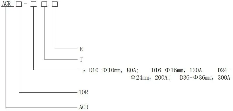
| E | E-Single-phase |
| T | T-External open current transformer |
| Open current transformer model: | |
| 10R | IOR-Rail-type installation |
| ACR | ACR series grid electrical instruments |
Product Function
| Function | Model
| ACR10R-DxxTE |
| Measurement Parameters | Single-phase current | ■ |
| Single-phase voltage | ■ | |
| Single-phase (active power, reactive power, power factor) | ■ | |
| Three-phase (active energy, reactive energy) | ■ |
Note:1.“■”refers to standard function, the standard configuration for above instruments is 1 channelRS485 communication.
Technical Parameters
| Technical parameters | Indicators | |||||
| Input | Grid | Single-phase, | ||||
| Frequency | 45~65Hz | |||||
| Voltage | AC 100V、400V Rated voltage: AC 100V, 400V | |||||
| Overload: 1.2 times the rated voltage(continuous); 2 times the rated voltage lasting for 1 second | ||||||
| 0.2VA Power consumption: less then 0.2VA | ||||||
| Current | Rated current: 10A,20A,40A,80A,120A,200A etc. (for details see product specifications) | |||||
| Overload: 1.2 times the rated current(continuous);10 times the rated current lasting for 1 second | ||||||
| Power consumption: less then 0.2VA | ||||||
| Output | Communication | RS485 interface, Modbus- RTU | ||||
| Display | LCD | |||||
| Measurement precision | Voltage: 0.2 level, current, power Active energy: 0.5 level,0.01Hz frequency, Reactive energy: 1 level | |||||
| Power supply | AC85~265V or DC100~350V; power consumption ≤10VA | |||||
| Safety | Power frequency withstand voltage | AC2kV 1 min between power supply // current input//voltage input and communication AC2kV 1 min between each pair of combinations among power supply, urrent input and voltage input. | ||||
| Insulating resistor | Input,output terminal to housing >100MΩ | |||||
| Environment | Working temperature: -10℃~+55℃;storage temperature: -20℃~+70℃ Relative humidity:5%~95%,non-condensing; altitude:≤2500m | |||||
Installation
Overall and Installation Dimensions (Unit: mm)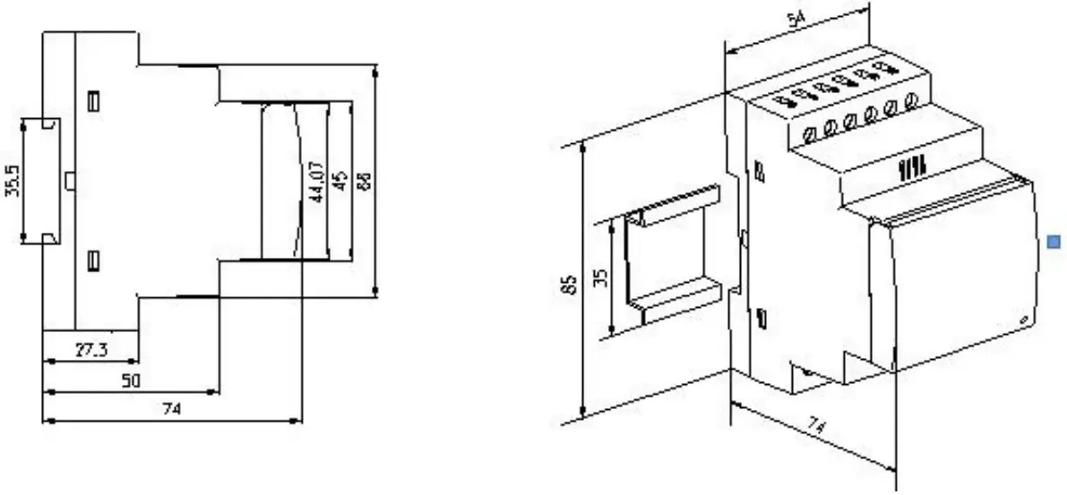
Open Current Transformer’s Dimension (Unit: mm)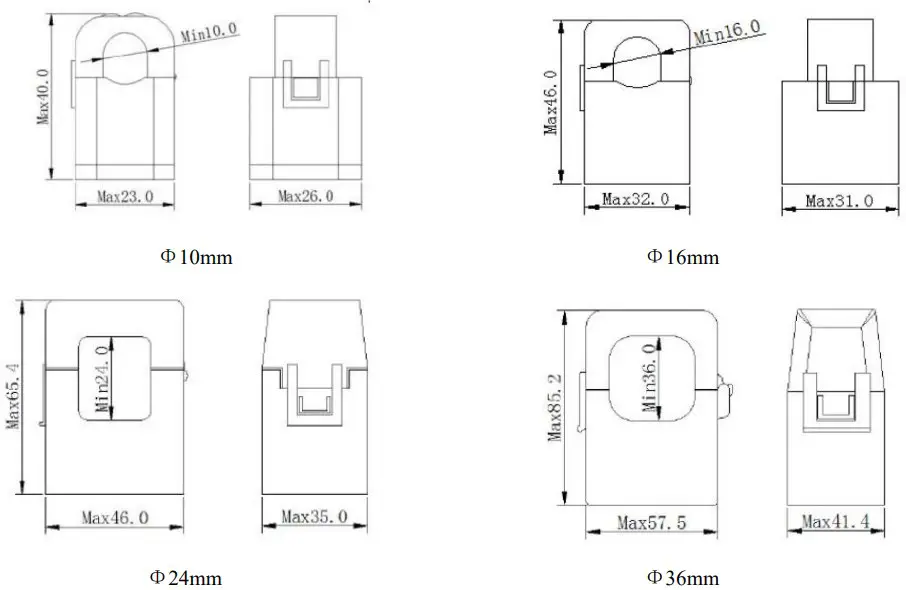
Installation Method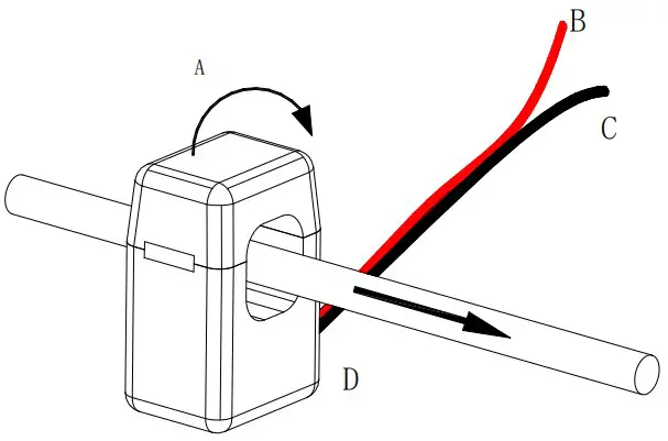
Installation Method of the Open Current Transformer Close
| A | Close according to the arrow direction |
| B | Positive (White) |
| C | Negative (Black) |
| D | Current direction |
Connection Mode
(Note: The connection diagram on the instrument housing shall prevail in case of any discrepancies with it)
Single-phase 1CT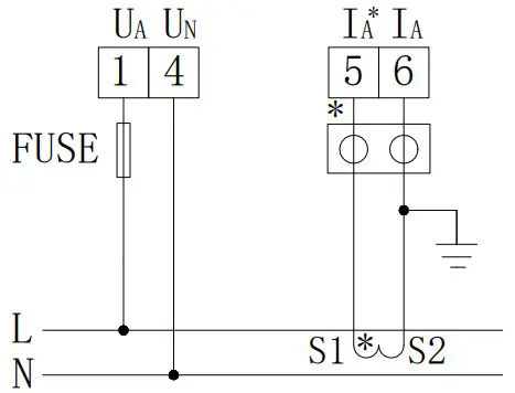
Single-phase 1PT, 1CT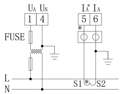
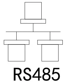
RS485 communication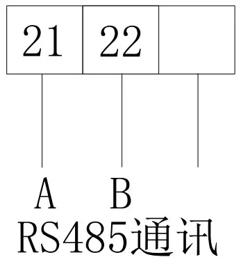
It is recommended to use 0.5A or 3A for the fuse in the connection diagram;
RS485 communication terminal connection can use either RJ45 female or normal connector.
Programming and Use
Panel Description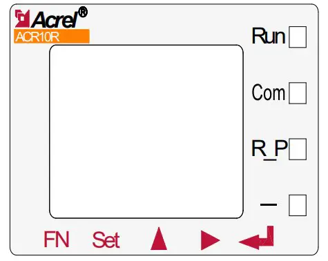
| Off | On | Flashing | |
| Run (Green) | The instrument is not running | / | The instrument is running normally |
| Com (Red) | The instrument is not communicating | / | The instrument is in communication status. |
| R-P (Red) | Positive power | Negative power | / |
| — (Red) | / | Negative value indicator lamp | / |
Button Function Description
The five buttons of the instrument are FN button, SET button,,,Enter button from left to right.
| FN button | The button function is not yet available. |
| SET button | In the measurement mode, press this button to enter the programming mode. The instrument will indicate entering password. When the correct password is entered, you can set the programming for the instrument; in the programming mode, use it to return to the previous menu |
| In the measurement mode, it is used to switch display items; In the programming mode, it is used to switch menus of the same level or reduce the units. | |
| In the measurement mode, it can be used to see relevant parameters. For details, see the display menu; In the programming mode, it is used to switch menus of the same level or increase the units. |
| Enter button | In the programming mode, it is used to confirm the items selected form the menu and the modification of parameters. |
| In the programming mode, the combination is used to reduce hundreds | |
| In the programming mode, the combination is used to increase hundreds |
The switch output of the instrument adopts relay output with two control mode:
- alarm mode(“SEL”is not zero);
- bus control mode (“SEL”is selected as “0. do” and level output for zero “dLy”.When “dLy” is not zero, it is automatically cut off after do action in the set delay time. )
Set Do output type in the “SEL”. “0. do” usually refers to communication control (if “dLy”is set to 0, the output is level or pulse. If dly is set to 2, the circuit will be off after closingfor two seconds) Others are alarm control (see list below).
“dLy”refers to alarm delay (which is not recommended to set as 0 to prevent disturbance or mistake.Pulse or level output control for Do output type)
“bAnd” refers to setting of the non-action band
AL.Hi” refers to the setting of high alarm humber (no need to set the max. 9999)
“AL.Lo” refers to the setting of low alarm number (no need to set the min. -9999
(The above three settings correspond to the energy display which contains decimal point. Eg.input220V 100A/5A, three-phase four-wire, the calculation of 100% P total is 220*100*3=66kW. If high alarmfor 100% power, return for 90% power, the “AL.Hi” can be set to 66.00, the “bAnd” to 6.00. If highalarm for 100% voltage, return for 95% voltage, the “AL.Hi” can be set to 220.0, the “bAnd” to11.0. If high alarm for 100% current, return for 95% current, the “AL.Hi” can be set to 100.0, the“bAnd” to 5.0)
“In.=0”refers to whether low alarm is allowed if the signal is 0. Lo. on enable it and Lo.of disable it.
| 01 | 02 | 03 | 04 | 05 | 06 | 07 | 08 |
| UA | UB | UC | Max/min value of three-phase phase voltage | UAB | UBC | UCA | Max/min value of three-phase linevoltage |
| 09 | 10 | 11 | 12 | 13 | 14 | 15 | 16 |
| IA | IB | IC | Max/min value of three-phase current | PA | PB | PC | P total |
| 17 | 18 | 19 | 20 | 21 | 22 | 23 | 24 |
| QA | QB | QC | Q total | SA | SB | SC | S total |
| 25 | 26 | 27 | 28 | 29 | 30 | 31 | |
| PFA | PFB | PFC | PF | F | Unbalanced voltage | Unbalanced current | |
Three-phase
| 01 | 02 | 03 | 04 | 05 | 06 | 07 |
| U | I | P | Q | S | PF | F |
Single-phase
Note: 1. Max/min value of three-phase ….refers to:maximum value for three-phase high alarm,minimum value for three-phase low alarm.
The second channel DO can set a“32.FL” combined alarm function. After setting, the 2nd level menuwill become “SEL”(Function Selection), “dLy”(Delay), “H U”(Overvoltage), “L-U”(Undervoltage),“H-F”(Overfrequency), “L F”(Underfrequency), “H-P”(Overpower), “L-P”(Underpower), “H-I”(Overcurrent), “L-PF”(Underpower Factor), “H-b.U”(Unbalanced Overvoltage. Missing phase for -1setting. The judgement conditions are at least one phase>0.2Ie, one phase<0.01Ie)
Unbalance calculation
(Difference between the max.mean deviation and the mean value)/mean value*100%. If the mean value
in the denomintor is less than the rated value, the denomintor will be the rated value.
Rated voltage value Ue: three-phase four-wire Ue is phase voltage. The 400Vinstrument set in themenu is 220V*PT, and 100V instrument is 57V*PT.
Rated current value Ie: 5A*CT for 5A instrument, 1A*CT for 1A instrument.
The parameter setting for the unblance is in the percentage form, such as 20 refers to 20%
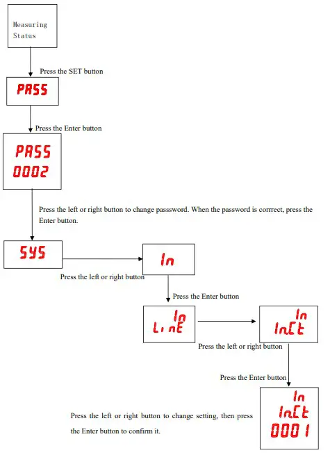
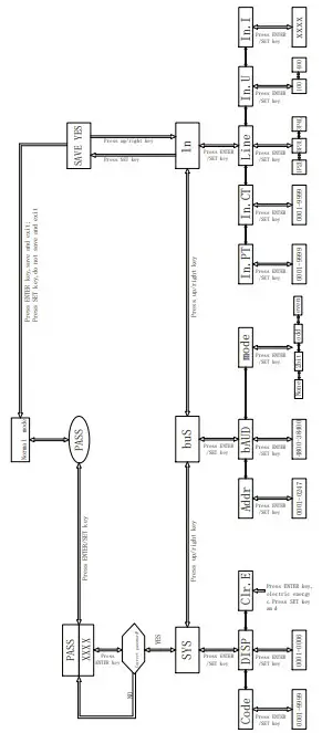
Programming Examples
This section introduces some option change in the programming menu in the form of work flowchart, such as the current multiplier, transformer setting.
Note: When the setting or selection is done, the Enter button must be pressed to confirm it. Afterthe confirmation is complete, continuously press the SET button until the SAVE/YES page appears. Atthis time, the Enter button must be pressed at this time or the setting will not be valid.
How to Change Current Multiplier (CT Transformation Ratio)
Programming Cases
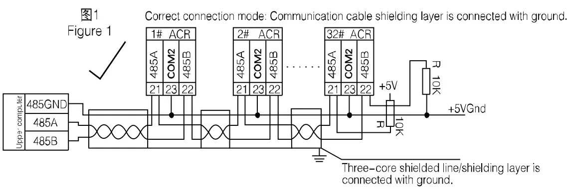
Communication Connection
The instrument provides asynchronous half-duplex RS485 communication interface wich adoptsMODBUS-RTU protocol so all kinds of data can be transmitted on the communication line. Theoretically,one communication line can be connected with up to 128 instruments, each of which can set a communicationaddress (Addr) and communication rate (baud) via setting.
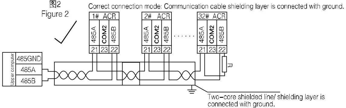
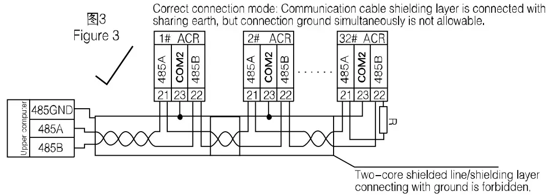
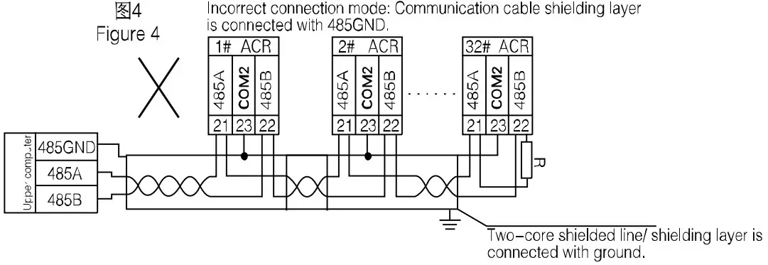
For the communication connection, we recommend to use the three-core shielding wire .The core wiresare connected to A,B,COM2 respectively and the shielding layer is connected to the ground. COM2 isforbidden to have ground connection. When laying the wires, the communication line shall be kept awayfrom the strong current cable or other strong electric field.
It is recommended to add a matching resistor between A and B of the end instruments. The resistancerange is 120Ω~10kΩ.
See 7.6 for specific connection case.
Transmitting Method
The information transmission is asynchronous and in bytes. The communication message tranmittedfrom the master to the slave is in 10-bit format including 1 start bit,8 data bit(LSB first delivered),noparity bit, one stop bit. If parity bit or 2 stop bit is et, the format is 11-bit.
Information Frame Format
Address code: the address code is in the beginning of the frame, which is composed of a byte (8bit binary code)representing 0~255 in decimal system. The PZ instrument only uses 1~247 and keepsother addresses. The bits indicate the address of the terminal device designated by the user. The device will receive the data from the linked master. The address of every terminal device must be unique.Only the end addressed will correspond to the query containing its address. When the terminal sendsback a response, the responding slave address will tell the master which terminal is communicatingwith it.
Function code: the function code tells the addressed termnial to carry out which functions. Thetable below lists up the function codes used by this instrument as well as their meanings and funcitons.
| Address code | Function code | Data zone | CRC check code |
| 1 byte | 1 byte | n byte(s) | 2 bytes |
Address code: the address code is in the beginning of the frame, which is composed of a byte (8bit binary code)representing 0~255 in decimal system. The PZ instrument only uses 1~247 and keepsother addresses. The bits indicate the address of the terminal device designated by the user. The device will receive the data from the linked master. The address of every terminal device must be unique.Only the end addressed will correspond to the query containing its address. When the terminal sendsback a response, the responding slave address will tell the master which terminal is communicatingwith it
Function code: the function code tells the addressed termnial to carry out which functions. Thetable below lists up the function codes used by this instrument as well as their meanings and funcitons.
| Function | Definition | Operation |
| 03H/04H | Data reading register | Obtaining the current binary value of one or more registers. |
| 10H | Preset multi-register | Set the binary value into a series of multi-register |
Data zone: the data zone contains the data needed for carrying out certain functions or collectedwhen the terminal responds to the query. The content of the data may be number, reference address orset value. For example: if the function code tells the terminal to read a register,the data zone needsto specifiy which register to start with and how much data to be read. The embedded address and datawill vary with types and different content of the slaves.
CRC check code:CRC field occupies two bytes including one 16-bit binary value. The CRC value iscalculated by the transmitting devicie then added to the data frame. The receiving device willrecalculate the CRC value upon receiving the data then compare it with the received value in the CRCfield. If the two values are not identical, there is an error.
The procedure to generate a CRC
Preset a 16-bit register as 0FFFFH (full 1), which is called CRC register.
Make XOR calculation with 8 bit of the first byte in the data frame and the lower byte in the CRCregister and store the result into the CRC register.
Shift the CRC register right a bit and fill the MSB with 0 and take out the LSB for checking.
If the LSB is 0, repeat step 3 (one more shift); if the LSB is 1, m,ake XOR calculation withCRC register and preset fixed value (0A001H).
Repeat step three and step four until the 8th shift. The entire 8 bit processing is complete inthis way.
Repeat step two to five to process the next 8 bits until all bytes are processed. Finally, the CRC register value becomes the CRC value.
Besides, there is also a wayt to calculate CRC using the preset table. It is characterized by rapid calculation speed. However, the table needs relatively large storage room. We willnot introduce it here, please refer to relevant materials
Function Code Introduction
Function Code 03H or 04H: Reading Register
The function allows the user to obtain the data collected and recorded by the device and system parameters. The data number requested by the master computer for one time has no limitation but cannot exceed the defined address range.
The following examples are 3 basic data read from 01 slave computer (every addressin the dataframe takes up 2 bytes):UAB, UBC, UCA. Among them, UAB’s address is 0028H, UBC’s address is 0029Hand UCA’s address is 002AH
| Sent by master | Sent message | |
| Address code | 01H | |
| Function code | 03H | |
| Start address | UB | 00H |
| LB | 28H | |
| Number of registers | UB | 00H |
| LB | 03H | |
| LB | 85H | |
| CRC check code | ||
| UB | C3H | |
| Feedback by slave | Feedback message | |
| ddress code | 01H | |
| Function code | 03H | |
| Bytes | 06H | |
| Register data | UB | Undefined |
| LB | Undefined | |
| Register data | UB | Undefined |
| LB | ||
| Undefined | ||
| Register data | UB | Undefined |
| LB | Undefined | |
| CRC Register data | LB | Undefined |
| UB | Undefined | |
Function Code 10H: Writing Register
The function code 10H allows the user to change the contents of multiple registers. The functioncode can be used to write the system parameters and switch output status. The master computer can writea maximum of 16 pieces of data (32 bytes) atonce.
The following example shows than when the preset address is 01, the switch outputis Do1. The switchinput/output status indication register’s address is 0022H. The 9 12 bit corresponds to DI1-DI4, the13-14 bit corresponds to D01-D02 respectively.
| Sent by master | Sent message | Feedback by slave | Feedback message | ||||
| Address code | 01H | Address code | 01H | ||||
| Function code | 10H | Function code | 10H | ||||
| Start address | UB | 00H | Start address | UB | 00H | ||
| LB | 22H | LB | 22H | ||||
| Register number | UB | 00H | Register number | UB | 00H | ||
| LB | 01H | LB | 01H | ||||
| Byte number | 02H | CRC check code | LB | A1H | |||
| 0022H data to be written | UB | 10H | UB | C3H | |||
| LB | 00H | ||||||
| CRC check code | LB | ADH | |||||
| UB | 12H | ||||||
Communication Application Details
he instrument design has a uniform planning for the communication address list. The user can easilyrealize the functions of remote measurement, remote signalling and remote control according to thefollowing introduction
Switch Input and Output
The switch input of the instrument adopts dry contact switch signal input method. The instrumentis equipped with +5V operating power inside so it does not needexternal power supply. When the externalcontact is close or open, the instrument will show the switch status locally. At the same time, thecommunication port of the instrument can realize the long distance transmission function, i.e., the“remote signalling” function.
When the switch output is the relay output, the instrument can not only be remotely controlledby the upper computer(two ways of remote control:1.level triggering 2. Pulse triggering) to realize“remote control” function but also realize corresponding alarm function upon customer’s request(such as overcurrent, undervoltage).
The communication address related to the switch input/output is 0022H with relations to the switchI/O as below:
| 0022H | 16 | 15 | 14 | 13 | 12 | 11 | 10 | 9 | 8~1 |
| DO2 | DO1 | DI4 | DI3 | DI2 | DI1 | Reserved |
Communication Address List (MODBUS-RTU Protocol)(1Float=2Word,1Word=8Byte)
| Address | Parameters | R/W attribute | Number range | Data type | Remarks | ||||||||
| 0000H | Protective password | R/W | 0001-9999 | word | |||||||||
| 0001H UB | Communication address | R/W | 0001-0247 | word | |||||||||
| 0001H LB | Baud rate | R/W | 0-3:38400、19200、 9600、 4800bps | ||||||||||
| 0002H | Reserved | R | Factory parameters. Users are not allowed to write an order. |
word | |||||||||
| 0003H | PT transformation ratio | R/W | 1-9 | word | |||||||||
| 0004H | CT transformation ratio | R/W | 1-9999 | word | |||||||||
| 0005H~0021H | Reserved | R | Factory parameters. Users are not allowed to write an order. | word | |||||||||
| 0022H | Switch I/O status | R/W | 7.3.2 | word | |||||||||
| 0061H | U | R | 0-65535 | word | 1 bit decimal is reserved | ||||||||
| 0062H~0063H | Reserved | R | word | ||||||||||
| 0064H | I | R | 0-65535 | word | 2 bit decimal is reserved | ||||||||
| 0065H~0066H | Reserved | R | word | ||||||||||
| 0067H | P | R | -32760―+32760 | word | 3 bit decimal is reserved, KW | ||||||||
| 0068H~006AH | Reserved | R | word | ||||||||||
| 006BH | Q | R | -32760―+32760 | word | 3 bit decimal is reserved, KVar | ||||||||
| 006CH~006EH | Reserved | R | word | ||||||||||
| 006FH | S | R | 0―65535 | word | 3 bit decimal is reserved, KVA | ||||||||
| 0070H~0072H | Reserved | R | word | ||||||||||
| 0073H | PF | R | 0-100 | word | 2 bit decimal is reserved | ||||||||
| 0074H~0076H | Reserved | R | word | ||||||||||
| 0077H | F | R | 4500-6500 | 2 bit decimal is reserved | |||||||||
| 0078H~007AH | Reserved | ||||||||||||
| Energy adress list below | |||||||||||||
| 0047H~0048H | Absorbing active energy | R | 0-99999999999 | Float | Primary energy | ||||||||
| 0049H~004AH | Releasing active energy | R | 0-99999999999 | Float | Primary energy | ||||||||
| 004BH~004CH | Reactive energy | R | 0-99999999999 | Float | Primary energy | ||||||||
| 004DH~004EH | Capacitive reactive energy | R | 0-99999999999 | Float | Primary energy | ||||||||
Communication Connection Cases
The communication connection cases are shown as below:
Suppport
Headquarter: Acrel Co., Ltd.
Add.:253 Yulu Rd., Jiading District, Shanghai, China
Tel.: (86)021-69158300 69158301 69158302
Fax: (86)021-69158303
Customer service hotline: 800-820-6632
Website:www.acrel.cn
Email: ACREL001@vip.163.com
Postal code: 201801
Manufacture base: Jiangsu Acrel Electric Appliance Manufacturing Co., Ltd.
Add.: Dongmeng Road 5, Nanzha Street, Jiangyin City
Tel.(Fax):(86)0510-86179970
Postal code: 214405
Email: JY-ACREL001@vip.163.com


