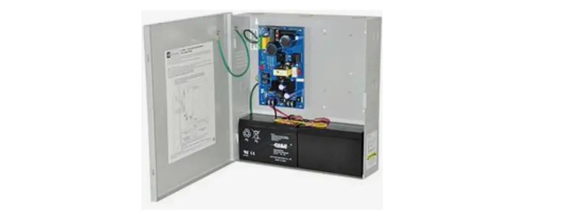
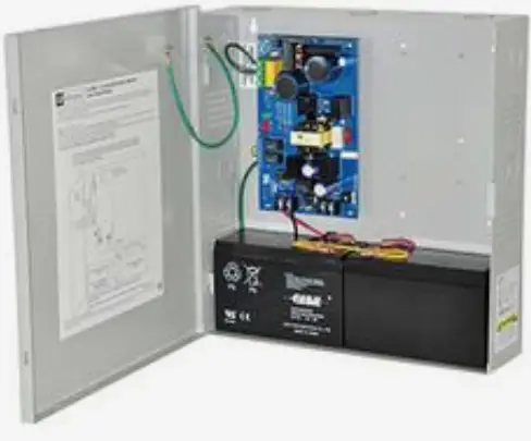
Altronix AL300ULX Power Supply Charger
Overview
Altronix AL300ULX is a power supply that converts a 115VAC, 60Hz input to a 12VDC or 24VDC regulating output. The AL300ULX is a base power supply unit for the UL Listed multi-output power supply/charger series: AL300ULPD4, AL300ULPD4CB, AL300ULPD8, AL300ULPD8CB, AL300ULXPD16, AL300ULXPD16CB AL300ULX Series Power Supply Configuration Reference Chart
|
Altronix Model Number | Accessory Power Distribution Modules | Number of Outputs | Fused Outputs | PTC Outputs auto resettable | Total Output Current A | Output Rating A per Output | Power Supply Input Fuse Rating | Power Supply Output Fuse Rating |
Agency Listings |
UL Listings and File Numbers |
|
AL300ULX AL300ULXX AL300ULXR |
|
1 |
|
|
2.5 |
2.5 |
5A/ 250V |
15A/ 32V |
Altronix Corp 140 58th St. Brooklyn, NY
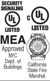
NYC Dept. of California Buildings State Fire Marshal | UL File # S4707 UL 294* UL Listed for Access Control System Units. UL 603 UL Listed for Power Supplies for Use with Burglar-Alarms Systems.
UL 1069 UL Listed Hospital Signaling and Nurse Call Equipment. UL 1481 UL Listed for Power Supplies for Fire Protective Signaling Systems
Signal Equipment Evaluated to CSA Standard C22.2 No.205-M1983 |
| AL300ULPD4 | PD4UL | 4 | ✓ | – | 2.5 | 3.5 | 5A/ 250V | 15A/ 32V |
| |
| AL300ULPD4CB | PD4ULCB | ✓ | 2.5 | |||||||
| AL300ULPD8 | PD8UL | 8 | ✓ | 2.5 | 3.5 | 5A/ 250V | 15A/ 32V | |||
| AL300ULPD8CB | PD8ULCB | ✓ | 2.5 | |||||||
| AL300ULXPD16 | Two (2) PD8UL | 16 | ✓ | 2.5 | 3.5 | 5A/ 250V | 15A/ 32V | |||
| AL300ULXPD16CB | Two (2) PD8ULCB | ✓ | 2.5 |

Access Control Performance Levels: Destructive Attack – I; Endurance IV Line Security – I; Stand-by Power – IV. AL300ULPD4(CB) and AL300ULPD8(CB) are available in larger enclosure. Add X to the model number e.g. AL300ULXPD4/CB.
Specifications
Input
Input 115VAC, 60Hz, 3.5A.
Output
- Class 2 Rated power-limited output(s).
- 12VDC or 24VDC selectable output(s).
- Burglar Alarm Aplications UL 603
- 12VDC = 10VDC-13.2VDC.
- 24VDC = 20VDC-26.4VDC.
- 2.5A total supply current.
- Filtered and electronically regulated outputs.
- Short circuit and thermal overload protection.
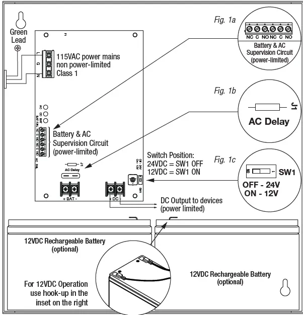
Supervision
- AC fail supervision form C contacts.
- Low battery and battery presence supervision form C contacts.
Battery Backup
- Built-in charger for sealed lead acid or gel type batteries.
- Automatic switch over to stand-by battery when AC fails.
- Maximum charge current 0.7A.
- Zero voltage drop when switched over to battery backup.
LED Indicators
AC input, DC output and Battery LED indicators.
Additional Features
- Power supply, enclosure, cam lock and battery leads.
- All models are available in red enclosure add an R suffix to the part #, e.g. AL300ULPD8R
Power Supply Output Specifications
| Output | Switch Position |
| 12VDC | SW1 – ON |
| 24VDC | SW1 – OFF |
Stand-by Specifications total current shown
| Output | 4 hr. of Standby and 5 Minutes of Alarm | 24 hr. of Stand by and 5 Minutes of Alarm | 60 hr. of Stand by and 5 Minutes of Alarm |
| 12VDC / 40AH Battery | Stand-by = 2.5A Alarm = 2.5A | Stand-by = 1.0A Alarm = 2.5A | Stand-by = 300mA Alarm = 2.5A |
| 24VDC / 12AH Battery | Stand-by = 200mA Alarm = 2.5A | ||
| 24VDC / 40AH Battery | Stand-by = 2.5A Alarm = 2.5A | Stand-by = 1.0A Alarm = 2.5A | Stand-by = 300mA Alarm = 2.5A |
CAUTION
De energize unit prior to servicing. For continued protection against risk of electric shock and fire hazard replace fuse with the same type and rating. Do not expose to rain or moisture.
CAUTION
When power supply board is set for 12VDC use only one 112VDC stand-by battery. Keep power-limited wiring separate from non power-limited. Use minimum 0.25 spacing.
Installation Instructions
Wiring methods shall be in accordance with the National Electrical Code/NFPA 70/NFPA 72/ANSI, and with all local codes and authorities having jurisdiction. Product is intended for indoor use only.
- Mount unit in the desired location. Mark and predrill holes in the wall to line up with the top two keyholes in the enclosure. Install two upper fasteners and screws in the wall with the screw heads protruding. Place the enclosure’s upper keyholes over the two upper screws; level and secure. Mark the position of the lower two holes. Remove the enclosure. Drill the lower holes and install two fasteners. Place the enclosure’s upper keyholes over the two upper screws. Install the two lower screws and make sure to tighten all screws Enclosure Dimensions.
- Secure enclosure to earth ground.
- Set the unit to the desired DC output voltage by setting SW1 to the appropriate position Power Supply Output Specification.
- Secure cabinet to earth ground. Connect AC power (115VAC, 60Hz to the terminals marked L, N
- Green AC LED on power supply board will turn on. This light can be seen through the LED lens on the door of the enclosure.
- Use 14 AWG or larger for all power connections attery.
- DC output, AC input. Use 22 AWG to 18 AWG for power-limited circuits AC fail/Low Battery reporting.
- Keep power-limited wiring separate from non power-limited wiring (115VAC, 60Hz Input, Battery Wires.
- Minimum 0.25 spacing must be provided.
CAUTION
Do not touch exposed metal parts. Shut branch circuit power before installing or servicing equipment. There are no user serviceable parts inside. Refer installation and servicing to qualified service personnel. For Fire Alarm applications the outputs are Special Applications only see list. For other devices contact Underwriters Laboratories to ensure compatibility.
- Measure output voltage before connecting device. This helps avoiding potential damage.
- When servicing the unit, AC mains should be removed.
- Connect devices to be powered:
- For AL300ULX Power Supply: connect devices to the terminals marked + DC –
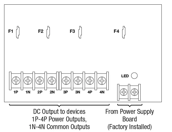
- For other Power Distribution Models: connect devices to be powered to the terminal pairs 1 to 4 marked 1P & 1N through 4P & 4N or 1 to 8 marked [1P & 1N] through 8P & 8N carefully observing correct polarity.
- For Access Control applications batteries are optional.
- When batteries are not used, a loss of AC will result in the loss of output voltage.
- When the use of stand-by batteries is desired, they must be lead acid or gel type.
- Connect one (1) 12VDC battery to the terminals marked [+ BAT –] for 12VDC operation.
- Use two (2) 12VDC batteries wired in series for 24VDC operation.
- Connect appropriate signaling notification devices to AC FAIL & BAT FAIL supervisory relay outputs.
Note
When used in fire alarm, burglar alarm or access control applications, AC Fail relay should be utilized to visually indicate that AC power is on. To delay report for 6 hours cut AC Delay jumper. Please ensure that the cover is secured with the provided key lock.
LED Diagnostics
Power Supply Board
| Red DC | Green AC | Power Supply Status |
| ON | ON | Normal operating condition. |
| ON | OFF | Loss of AC. Stand by battery is supplying power. |
| OFF | ON | No DC output. |
| OFF | OFF | Loss of AC. Discharged or no stand-by battery. No DC output. |
| Red Bat | Battery Status |
| ON | Normal operating condition. |
| OFF | Battery fail/low battery. |
Power Distribution Module
| Green | Power Distribution Module Status |
| ON | Normal operating condition. |
| OFF | No Power Output. |
Terminal Identification
Power Supply Board
| Terminal Legend | Function/Description |
| L, G, N | Connect 115VAC 60Hz. to these terminals: L to Hot, N to Neutral. Do not use the [G] terminal. |
| + DC – | 12VDC or 24VDC 2.5A continuous power-limited output. |
| AC Fail NC, C, NO | Indicates loss of AC power, e.g. connect to annunciator/alarm panel. Relay normally ener- gized when AC power is present. Contact rating 1A 28VDC. AC Fail condition will report approximately within one 1 minute after loss of AC. To delay report for 6 hours cut jumper J1 on the Power Supply Board (AC trouble output delay option). If this mode is selected, the Power Supply Board must be reset by removing all power to it for 30 seconds. |
| Bat Fail NC, C, NO | Indicates low battery condition, e.g. connect to alarm panel. Relay normally energized when DC power is present. Contact rating 1A 28VDC. Low battery conditions will report approximately 21VDC 24VDC output setting or approximately 10.5VDC 12VDC output setting). Battery presence detection will report approximately 1 minute after battery remains undetected missing or removed. |
| + BAT | Stand-by battery connections. Maximum charge current 0.7A. |
Power Distribution Module
| Terminal Legend | Function/Description | |
| PD4UL/PD4ULCB | PD8UL/PD8ULCB | |
| 1P to 4P | 1P to 8P | Positive DC power outputs. |
| 1N to 4N | 1N to 8N | Negative DC power outputs. |
Power Distribution Modules
PD4UL Power Distribution Board Non Power Limited Outputs
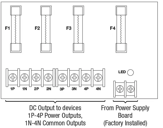
PD4ULCB – Power Distribution Board Class 2 Power-Limited Outputs
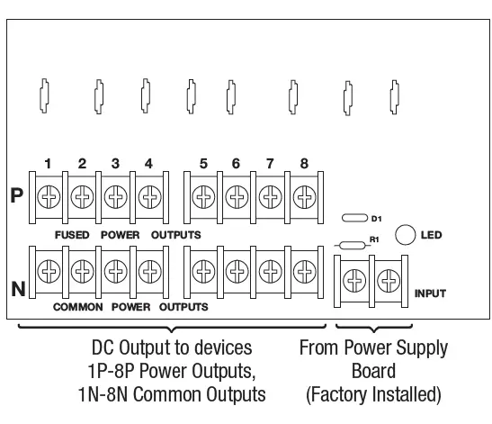
PD8UL Power Distribution Board Non Power-Limited Outputs
Replace fuses with the same type and rating 3.5A/250V
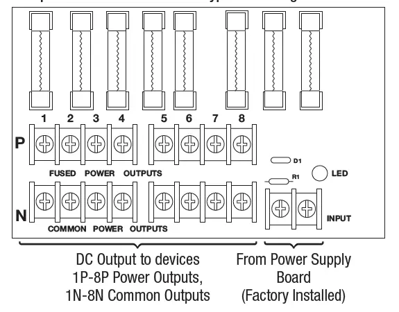
PD8ULCB – Power Distribution Board Class 2 Power-Limited Outputs
Appendix A – UL Listed Compatible Devices
Four (4) Wire Smoke Detectors
Below lists four (4) wire smoke detectors compatible with AL300ULX output.
| System Sensor Smoke Detector/Base | Detector Type | Max Stand-by Current mA | Alarm Current mA |
| B112LP | Base | 0.12 | 36 |
| B114LP | Base | ||
| B404B | Base | ||
| DH100ACDC | Photoelectric | 0.15 | 0.70 |
| DH100ACDCLP | Photoelectric | 0.15 | 0.70 |
| DH100ACDCLPW | Photoelectric | 0.15 | 0.70 |
| DH400ACDCI | Ionization Duct | 25 | 95 |
| DH400ACDCP | Photoelectric Duct | 25 | 95 |
| 1112/24/D | Ionization | 0.05 | 50 |
| 1424 | Ionization | 0.10 | 41 |
| 1451 (w/B402B Base) | Ionization | 0.10 | 39 |
| 2112/24ATR | Photoelectric | 0.50 | 60/70 |
| 2112/24AITR | Photoelectric | 0.50 | 60/70 |
| 2112/24/D | Photoelectric | 0.05 | 50 |
| 2112/24T/D | Photoelectric w/135o Thermal | 0.05 | 50 |
| 2112/24TSRB | Photoelectric w/135o Thermal Supervisory Relay | 15 | 45 |
| 2312/24TB | Photoelectric | 0.12 | 50 |
| 2412 12 volt | Photoelectric | 0.12 | 77 |
| 2424 | Photoelectric | 0.10 | 41 |
| 2451 | Photoelectric | 0.10 | 39 |
| 2451TH with/B402B Base | Photoelectric | 0.10 | 39 |
| 2W-MOD | Loop Test/Maintenance Mod. | 30 | 50 |
| 4W-B 12/24 volt | Photoelectric I3 | 0.05 | 23 |
| 4WT-B 12/24 volt | Photoelectric I3 w/Therm | 0.05 | 23 |
| 4WTA-B 12/24 volt) | I3 Photo w/Therm/Sounder | 0.05 | 35 |
| 4WTR-B 12/24 volt | I3 Photo w/Therm/Relay | 0.05 | 35 |
| 4WITAR-B 12/24 volt | I3 Photo w/Isolated Therm/Sounder/Relay | 0.05 | 50 |
| 2W-MOD2 | I3 Loop Test/Maintenance Mod. | 0.05 | |
| RRS-MOD | I3 Reversing Relay/Sync Module | 0.05 | |
| 6424 | Projected Beam | 10 | 28.4 |
| Beam 1224S | Projected Beam | 17 | 38.5 |
Contact manufacturer for current draws.
Relays
Table lists relays compatible with AL300ULX output
| Manufacturer | Model | Current mA |
| PR-1 | 15 | |
| PR-2 | 30 | |
| System Sensor | PR-3 EOLR-1 | 30 30 |
| R-10T | 23 | |
| R-14T | 23 |
| Manufacturer | Model | Current mA |
| R-20T | 40 | |
| R-24T | 40 | |
| System Sensor | R-10E R-14E | 23 23 |
| R-20E | 40 | |
| R-24E | 40 |
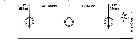
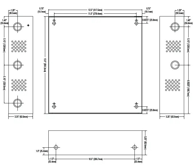
Enclosure Dimensions BC300
AL300ULX, AL300ULXR, AL300ULPD4, AL300ULPD4CB, AL300ULPD8, AL300ULPD8CB 13.5 x 13 x 3.25 (342.9mm x 330.2mm x 82.6mm
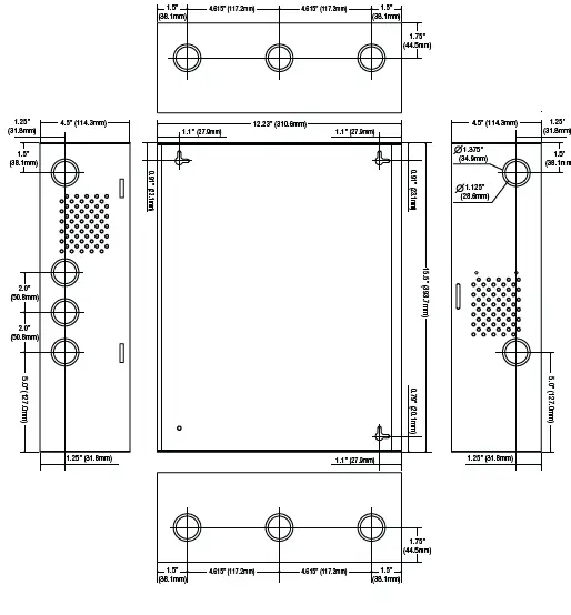
Enclosure Dimensions BC400
AL300ULXX, AL300ULXXR, AL300ULXPD4, AL300ULXPD4CB, AL300ULXPD8, AL300ULXPD8CB, AL300ULXPD16, AL300ULXPD16CB 15.5 x 12 x 4.5 393.7mm x 304.8mm x 114.3mm
Altronix is not responsible for any typographical errors 140 58th Street, Brooklyn, New York 11220
- USA phone: 718-567-8181
- Fax: 718-567-9056
- website: www.altronix.com
- e-mail: [email protected]
- Lifetime Warranty IIAL300ULX Series G01U


