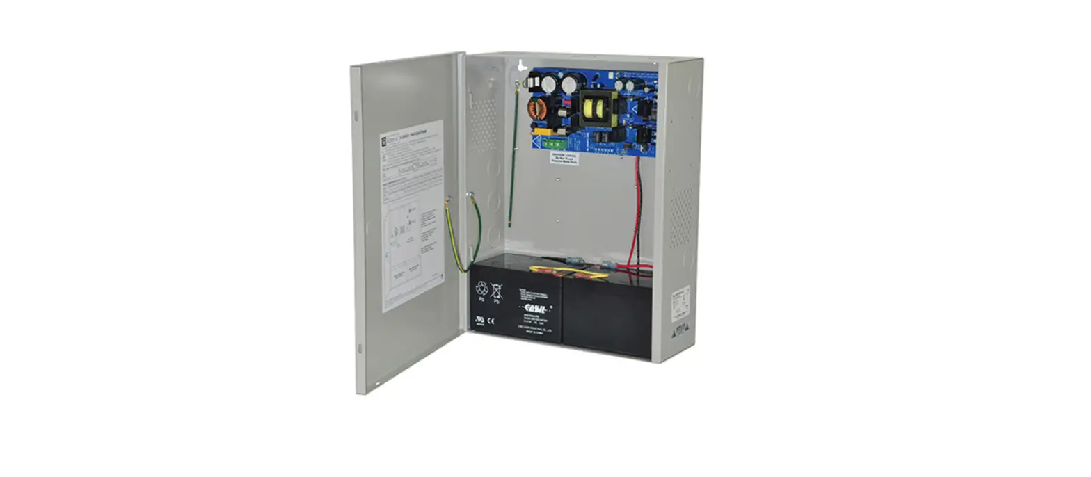
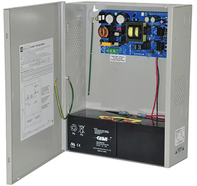
Altronix AL1024ULX Series Power Supply and Charger
Overview:
Altronix AL1024ULX is a power supply that converts a 115VAC / 60Hz input to a 24VDC regulating output (see specifications below). The AL1024ULX is the base power supply unit for the UL Listed multi-output power supply/charger series: AL1024ULXPD4, AL1024ULXPD4CB, AL1024ULXPD8, AL1024ULXPD8CB, AL1024ULXPD16, AL1024ULXPD16CB (Refer to AL1024ULX Series Power Supply Configuration Reference Chart below).
AL1024ULX Series Power Supply Configuration Reference Chart:
|
Altronix Model Number | Accessory Power Distribution Module(s) | Number of Output(s) | Fused Outputs | Class 2 Rated PTC Protected Power-Limited Outputs (auto-resettable) | Output Rating (A) per Output | Power Supply Input Fuse Rating | Power Supply Output Fuse Rating |
Agency Listings |
UL Listings and File Numbers |
|
AL1024ULX(R) |
– |
1 |
– |
– |
10 |
5A/ 250V |
15A/ 32V |
Altronix Corp. 140 58th St. Brooklyn, NY
California Factory State Fire Mutual Marshal Approved LISTED NFPA 72 Compliant (Fire-Protective Signaling Service). | UL File # S4707 UL 294* UL Listed for Access Control System Units. –––––––– UL 1481 UL Listed for Power Supplies for Fire Protective Signaling Systems –––––––– “Signal Equipment” Evaluated to CSA Standard C22.2 No.205-M1983 |
| AL1024ULXPD4 | PD4UL | 4 | P | – | 3.5 | 5A/ 250V | 15A/ 32V | LISTED NFPA 72 Compliant (Fire-Protective Signaling Service). | |
| AL1024ULXPD4CB | PD4ULCB | 4 | – | P | 2.5 | 5A/ 250V | 15A/ 32V | ||
| AL1024ULXPD8 | PD8UL | 8 | P | – | 3.5 | 5A/ 250V | 15A/ 32V | ||
| AL1024ULXPD8CB | PD8ULCB | 8 | – | P | 2.5 | 5A/ 250V | 15A/ 32V | ||
| AL1024ULXPD16 | Two (2) PD8UL | 16 | P | – | 3.5 | 5A/ 250V | 15A/ 32V | ||
| AL1024ULXPD16CB | Two (2) PD8ULCB | 16 | – | P | 2.5 | 5A/ 250V | 15A/ 32V |
*Access Control Performance Levels:
Destructive Attack – I; Endurance – IV; Line Security – I; Stand-by Power: 12AH – II, 65AH – IV. Do not exceed total output rating of 10A per unit.
Stand-by Specifications (total current shown):
| Output | 15 min. of Stand-by and 5 min. of Alarm | 4 hr. of Stand-by and 5 min. of Alarm | 24 hr. of Stand-by and 5 min. of Alarm | 60 hr. of Stand-by and 5 min. of Alarm |
| 24VDC/12AH Battery | Stand-By = 8A Alarm = 10A | Stand-By = 1.5A Alarm = 10A | Stand-By = 200mA Alarm = 10A | Stand-By = 100mA Alarm = 10A |
| Output | 15 min. of Stand-by and 5 min. of Alarm | 4 hr. of Stand-by and 5 min. of Alarm | 24 hr. of Stand-by and 15 min. of Alarm | 60 hr. of Stand-by and 15 min. of Alarm |
| 24VDC/65AH Battery | – | Stand-By = 8.0A Alarm = 10A | Stand-By = 1.5A Alarm = 10A | Stand-By = 500mA Alarm = 10A |
For Access Control applications, battery capacity for 10A supply current – 1 hr. for 24VDC/12AH battery, 6.5 hrs. for 24VDC/65AH battery. See battery size calculation worksheet for other batteries (Page 9). AL1024ULX Series Installation Guide
Specifications:
Input:
- Input 115VAC, 60Hz, 4.2A.
Output:
- 24VDC output.
- 8A supply current in non-alarm condition with 10A supply current during alarm for Fire Alarm Applications. 10A supply current for Access Control Applications.
- Filtered and electronically regulated outputs.
- Short circuit and thermal overload protection.
Supervision:
- AC fail supervision (form “C” contacts).
- Low battery supervision (form “C” contacts).
- Battery presence supervision (form “C” contacts).
Battery Backup:
- Built-in charger for sealed lead acid or gel type batteries.
- Automatic switch over to stand-by battery when AC fails.
- Maximum charge current 3.6A.
- Zero voltage drop when switched over to battery backup.
LED Indicators:
- AC input and DC output LED indicators.
Additional Features:
- Power supply, enclosure, cam lock, and battery leads
- All models are available in red enclosure (add an “R” suffix to the part #, e. g. AL1024ULXPD8R).
Installation Instructions:
Wiring methods shall be in accordance with the National Electrical Code/NFPA 70/NFPA 72/ANSI, and with all local codes and authorities having jurisdiction. Product is intended for indoor use only.
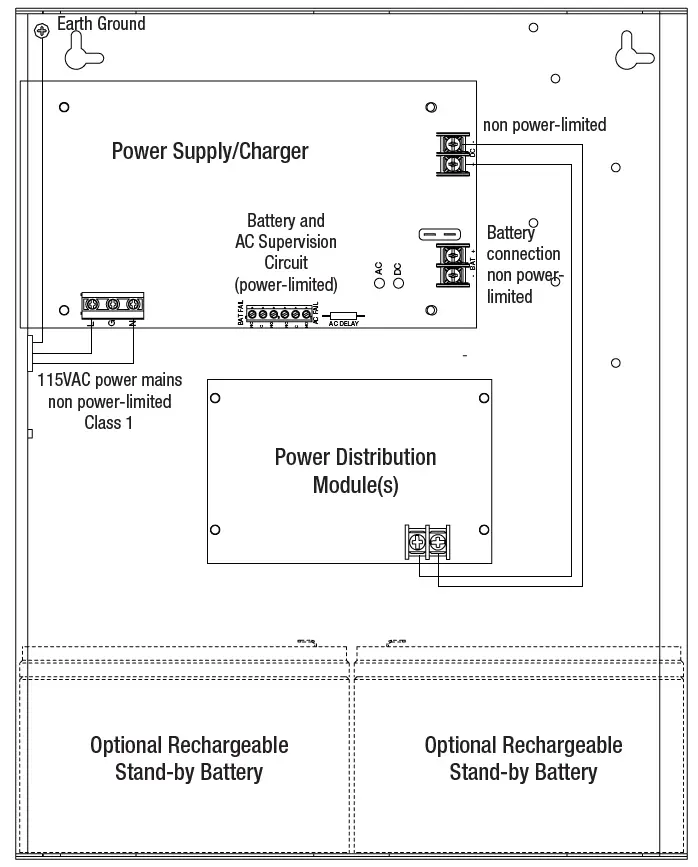
- Mount unit in the desired location. Mark and predrill holes in the wall to line up with the top two keyholes in the enclosure. Install two upper fasteners and screws in the wall with the screw heads protruding. Place the enclosure’s upper keyholes over the two upper screws; level and secure. Mark the position of the lower two holes. Remove the enclosure. Drill the lower holes and install three fasteners. Place the enclosure’s upper keyholes over the two upper screws. Install the two lower screws and make sure to tighten all screws (Enclosure Dimensions, pg. 8). Secure enclosure to earth ground.
- Connect AC power (115VAC, 60 Hz) to the terminals marked [L, N] (Fig. 1, pg. 5). Green “AC” LED on power supply board will turn on. This light can be seen through the LED lens on the door of the enclosure. Use 14 AWG or larger for all power connections (Battery, DC output, AC input). Use 22 AWG to 18 AWG for power-limited circuits (AC Fail/Low Battery reporting). Keep power-limited wiring separate from non power-limited wiring (115VAC, 60Hz Input, Battery Wires). Minimum 0.25” spacing must be provided.
CAUTION: Do not touch exposed metal parts. Shut branch circuit power before installing or servicing equipment. There are no user serviceable parts inside. Refer installation and servicing to qualified service personnel. For Fire Alarm applications the outputs are “Special Applications” only, see list (refer to Appendix A, pg. 6). For other devices contact Underwriters Laboratories to ensure compatibility. - Measure output voltage before connecting device. This helps avoiding potential damage. When servicing the unit AC mains should be removed.
- Connect devices to be powered:
- a. For AL1024ULX Power Supply: connect devices to the terminals marked [+ DC –] (Fig. 1, pg. 5)
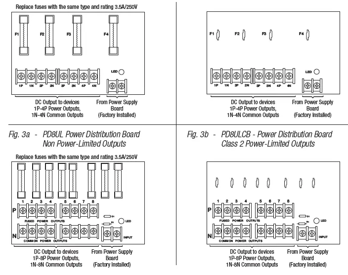
- . For other Power Distribution Models: connect devices to be powered to terminal pairs 1 to 4 marked[1P & 1N] through [4P & 4N] (Fig. 2a & 2b, pg. 7) or 1 to 8 marked [1P & 1N] through [8P & 8N] (Fig. 3a & 3b, pg. 7), carefully observing correct polarity.
- For Access Control applications batteries are optional. When batteries are not used, a loss of AC will result in the loss of output voltage. When the use of stand-by batteries is desired, they must be lead acid or gel type.
- Connect appropriate signaling notification devices to the terminals marked [AC FAIL & BAT FAIL]
(Fig. 1, pg. 5) supervisory relay outputs.
Note: When used in fire alarm, burglar alarm or access control applications, “AC Fail” relay must be used to provide a visual indication of AC power on. - Please ensure that the cover is secured with the provided Key Lock.
CAUTION: De-energize unit prior to servicing. For continued protection against risk of electric shock and fire hazard replace fuse with the same type and rating. Do not expose to rain or moisture.
CAUTION: Optional rechargeable stand-by batteries must match the power supply output voltage setting. Keep power-limited wiring separate from non power-limited. Use minimum 0.25″ spacing.
Wiring:
Use 14 AWG or larger for all power connections.
Note: Take care to keep power-limited circuits separate from non power-limited wiring (115VAC, Battery).
Maintenance
Unit should be tested at least once a year for the proper operation as follows:
Output Voltage Test: Under normal load conditions the DC output voltage should be checked for proper voltage level. Battery Test: Under normal load conditions check that the battery is fully charged, check specified voltage both at the battery terminal and at the board terminals marked [– BAT +] to ensure that there is no break in the battery connection wires.
Note: Maximum charging current under discharges is 3.6A.
Note: Expected battery life is 5 years; however, it is recommended changing batteries in 4 years or less if needed.
LED Diagnostics:
AL1024ULXB2 – Power Supply Board
| Red (DC) | Green (AC) | Power Supply Status |
| ON | ON | Normal operating condition. |
| ON | OFF | Loss of AC. Stand-by battery is supplying power. |
| OFF | ON | No DC output. |
| OFF | OFF | Loss of AC. Discharged or no stand-by battery. No DC output. |
PD4UL/PD4ULCB/PD8UL/PD8ULCB – Power Distribution Module
| Green (AC) | Power Distribution Module Status |
| ON | Normal operating condition. |
| OFF | No Power Output. |
Terminal Identification:
AL1024ULXB2 – Power Supply Board
| Terminal Legend | Function/Description |
| L, N | Connect 115VAC 60Hz to these terminals: L to hot, N to neutral. Do not use the [G] terminal. |
| + DC – | 24VDC @ 8A continuous, 10A in alarm non power-limited output. 10A continuous when batteries are not used |
| AC Fail NC, C, NO | Indicates loss of AC power, e.g. connect to audible device or alarm panel. Relay normally energized when AC power is present. Contact rating 1A @ 28VDC. AC or brownout fail is reported within 1 minute of event. To delay reporting for up to 6 hrs., cut “AC delay” jumper and reset power to unit. |
| Bat Fail NC, C, NO | Indicates low battery condition, e.g. connect to alarm panel. Relay normally energized when DC power is present. Contact rating 1A @ 28VDC. A removed battery is reported within 5 minutes. Battery reconnection is reported within 1 minute. Low battery threshold: 24VDC output threshold set @ approximately 21VDC. |
| – BAT + | Stand-by battery connections. Maximum charge current 3.6A. |
PD4UL/PD4ULCB/PD8UL/PD8ULCB – Power Distribution Module
| Terminal Legend | Function/Description | |
| PD4UL/PD4ULCB | PD8UL/PD8ULCB | |
| 1P to 4P | 1P to 8P | Positive DC power outputs |
| 1N to 4N | 1N to 8N | Negative DC power outputs |
Power Distribution Module(s):
Appendix A – UL Listed Compatible Devices
| System Sensor Smoke Detector/Base | Detector Type | Max Stand-by Current (mA) | Alarm Current (mA) |
| B112LP | Base | 0.12 | 36 |
| B114LP | Base | * | * |
| B404B | Base | * | * |
| DH100ACDC | Photoelectric | 0.15 | 0.70 |
| DH100ACDCLP | Photoelectric | 0.15 | 0.70 |
| DH100ACDCLPW | Photoelectric | 0.15 | 0.70 |
| DH400ACDCI | Ionization Duct | 25 | 95 |
| DH400ACDCP | Photoelectric Duct | 25 | 95 |
| 1112/24/D | Ionization | 0.05 | 50 |
| 1424 | Ionization | 0.10 | 41 |
| 1451 (w/B402B Base) | Ionization | 0.10 | 39 |
| 2112/24ATR | Photoelectric | 0.50 | 60/70 |
| 2112/24AITR | Photoelectric | 0.50 | 60/70 |
| 2112/24/D | Photoelectric | 0.05 | 50 |
| 2112/24T/D | Photoelectric w/135o Thermal | 0.05 | 50 |
| 2112/24TSRB | Photoelectric w/135o Thermal Supervisory Relay | 15 | 45 |
| 2312/24TB | Photoelectric | 0.12 | 50 |
| 2412 (12 volt) | Photoelectric | 0.12 | 77 |
| 2424 | Photoelectric | 0.10 | 41 |
| 2451 | Photoelectric | 0.10 | 39 |
| 2451TH (with/B402B Base) | Photoelectric | 0.10 | 39 |
| 2W-MOD | Loop Test/Maintenance Mod. | 30 | 50 |
| 4W-B (12/24 volt) | Photoelectric I3 | 0.05 | 23 |
| 4WT-B (12/24 volt) | Photoelectric I3 w/Therm | 0.05 | 23 |
| 4WTA-B (12/24 volt) | I3 Photo w/Therm/Sounder | 0.05 | 35 |
| 4WTR-B (12/24 volt) | I3 Photo w/Therm/Relay | 0.05 | 35 |
| 4WITAR-B (12/24 volt) | I3 Photo w/Isolated Therm/Sounder/Relay | 0.05 | 50 |
| 2W-MOD2 | I3 Loop Test/Maintenance Mod. | 0.05 | * |
| RRS-MOD | I3 Reversing Relay/Sync Module | 0.05 | * |
| 6424 | Projected Beam | 10 | 28.4 |
| Beam 1224(S) | Projected Beam | 17 | 38.5 |
A.2 Relays
Table A-2 below lists relays compatible with AL1024ULX output.
| Manufacturer | Model | Current (mA) |
| PR-1 | 15 | |
| PR-2 | 30 | |
| System Sensor | PR-3 EOLR-1 | 30 30 |
| R-10T | 23 | |
| R-14T | 23 |
| Manufacturer | Model | Current (mA) |
| R-20T | 40 | |
| R-24T | 40 | |
| System Sensor | R-10E R-14E | 23 23 |
| R-20E | 40 | |
| R-24E | 40 |
Battery Size Calculation Worksheet:
- A. AL1024ULX series internal current consumption: 0.05 A
- B. Load current consumption: A
- C. Stand-by time required (hours): H
- D. Battery capacity required for stand-by: AH
- E. AL1024ULX series internal power consumption: 0.05A
- F. Load current consumption: A
- G. Alarm duration (Hours; 15 Min. = 0.25 Hour): H
- H. Battery capacity required for Alarm: AH
- I. Total calculated battery capacity: AH
- J. Battery capacity required: AH
Note: AL1024ULX series power supply is designed to work with batteries up to 65AH. Please note: line [I] must not exceeds 36AH. You have to reduce either stand-by current consumption or stand-by time in order to comply with requirement. To determine actual battery size please round line [J] to the nearest larger standard battery size (e.g. 3.5 AH = 4.0 AH)


