
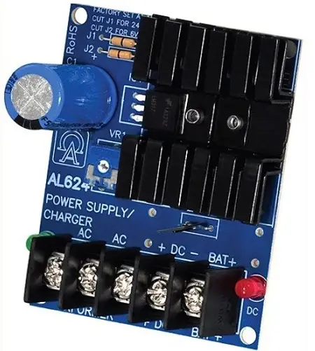
Altronix AL624E Linear Power Supply/Charger
Overview
Altronix AL624E Linear Power Supply/Charger converts a low voltage AC input to a low voltage DC output. This general purpose power supply has a wide range of applications for access control, security and CCTV system accessories that require additional power.
Specifications
Agency Listing:
- CE European Conformity.
Input:
- Input 16VAC to 24VAC, 20VA to 40VA (Voltage Output/Transformer Selection Table)
Output:
- Switch selectable 6VDC-12VDC-24VDC.
- 1.2A continuous supply current at 6VDC-12VDC.
- 750mA continuous supply current at 24VDC.
- Filtered and electronically regulated output.
Battery Backup:
- Built-in charger for sealed lead acid or gel type batteries.
- Maximum charge current 300mA.
- Automatic switchover to stand-by battery when
AC fails.
- PTC battery protection.
Additional Features:
- Thermal and short circuit protection with auto reset.
- AC input and DC output LED indicators.
- Extremely compact design.
- Includes battery leads and enclosure.
Enclosure Dimensions (H x W x D):
8.5” x 7.5” x 3.5” (215.9mm x 190.5mm x 88.9mm).
Voltage Output/Transformer Selection Table
| Output (continuous supply current) | Voltage Selector (JMPR) | Transformer |
| 6VDC @1.2A | Cut Jumper J2 Only | 12VAC / 20 VA (Altronix model TP1220) |
| 12VDC @ 1.2A | Leave J1 & J2 Intact | 16.5VAC / 20 VA (Altronix model TP1620) |
| 24VDC @ 750mA | Cut Jumper J1 Only | 24VAC / 40 VA (Altronix model TP2440) |
Installation Instructions
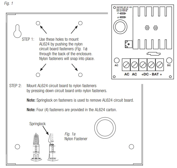
- Mount AL624 into an enclosure (Fig. 1, pg. 2).
- Mount AL624E in desired location.
- The unit is factory set for 12VDC. For 6VDC output cut jumper J2, for 24VDC output cut Jumper J1.
- Connect proper transformer to terminals marked [AC] (Voltage Output/Transformer Selection Table).
Use 18 AWG or larger for all power connections (Battery, DC output). - Measure output voltage before connecting devices. This helps avoid potential damage.
- Connect devices to be powered to the terminals marked [+ DC] and [DC – BAT] carefully observing polarity.
- Connect the battery to the terminals marked [BAT +] and [DC – NEG] (battery leads included).
Note: When batteries are not used, a loss of AC will result in a loss of output voltage.
LED Diagnostics
| Red (DC) | Green (AC) | Power Supply Status |
| ON | ON | Normal operating conditions |
| ON | OFF | Loss of AC. Stand-by battery is supplying power. |
| OFF | ON | No DC output. Short circuit or thermal overload condition. |
| OFF | OFF | No DC output. Loss of AC. Discharged or no battery present. |
Terminal Identification
| Terminal Legend | Function/Description |
| AC/AC | Low voltage AC input (Voltage Output/Transformer Selection Table, pg.1). |
| + DC – | 6VDC or 12VDC @ 1.2A continuous supply current. |
| – BAT + | Stand-by battery connections. Maximum charge rate 300mA. |
Altronix is not responsible for any typographical errors
140 58th Street, Brooklyn, New York 11220 USA | phone: 718-567-8181 | fax: 718-567-9056
website: www.altronix.com | e-mail: [email protected] | Lifetime Warranty IIAL624E – Rev. 091211 F21U


