![]() EZ Mount
EZ Mount
Load Cell Mounting Kit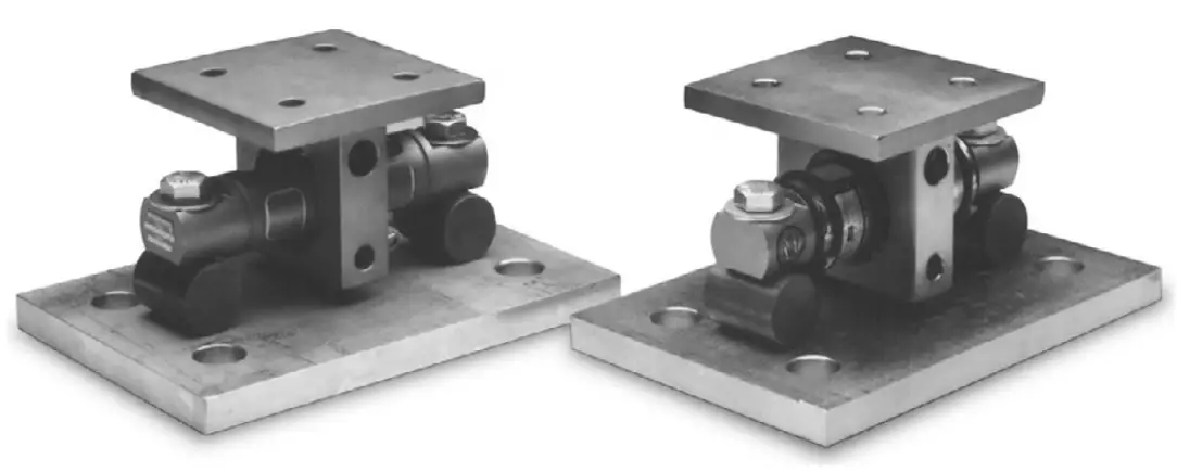
© Rice Lake Weighing Systems. All rights reserved.
Rice Lake Weighing Systems® is a registered trademark of Rice Lake Weighing Systems.
All other brand or product names within this publication are trademarks or registered trademarks of their respective companies.
All information contained within this publication is, to the best of our knowledge, complete and accurate at the time of publication. Rice Lake Weighing Systems reserves the right to make changes to the technology, features, specifications and design of the equipment without notice.
The most current version of this publication, software, firmware and all other product updates can be found on our website: www.ricelake.com
Revision History
This section tracks and describes manual revisions for awareness of major updates.
| Revision | Date | Description |
| E | January 12, 2023 | Established revision history; altered figures |
Table i. Revision Letter History
Introduction
The installation should be planned by a qualified structural engineer.
Each installation is unique, this manual is meant to serve as a general guideline for installation. Manuals and additional resources are available on the Rice Lake Weighing Systems website at www.ricelake.com
Warranty information can be found on the website at www.ricelake.com/warranties
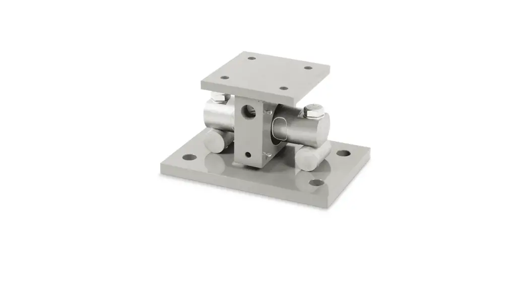
The EZ Mount Kit provides an extremely accurate method for weighing medium and large capacity tanks and hoppers that are subject to large thermal expansion/contraction or vibration forces. The design uses a double ended shear beam load cell (700 Ω bridge) and transmits the load with a sliding pin on the load-bearing groove of the cell. This design is very effective in providing for thermal expansion/contraction with little friction.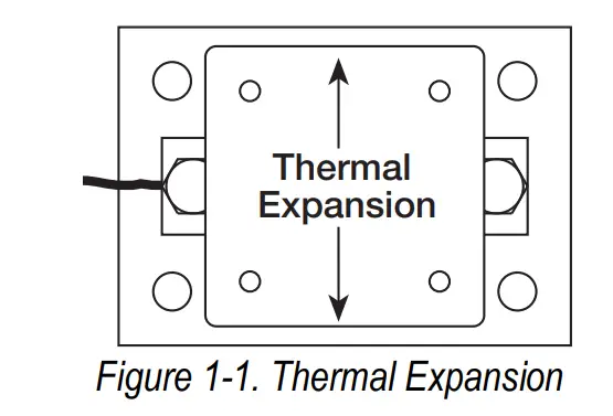
In the majority of applications, the assemblies are self-checking and held captive with no need for check or stay rods, making this mount a good choice for areas with frequent seismic activity.
The sliding pin design eases load cell installation and replacement without the need to raise the weighed vessel a large amount, which may disturb piping and other connections.
The EZ Mount is available in mild steel or stainless steel in five sizes from 5,000 lb – 250,000 lb.
The mount is compatible with RL70000 and RTI 5103 mild steel load cells in capacities from 5,000 lb – 250,000 lb. The EZ Mount is also available in stainless steel with RL70000SS and RTI 9103 in capacities from 5,000 lb – 150,000 lb. The RL72019SS hermetically-sealed stainless steel load cells are available in capacities from 5,000 lb – 60,000 lb.
1.1 Safety
Safety Definitions:![]() DANGER: Indicates an imminently hazardous situation that, if not avoided, will result in death or serious injury. Includes hazards that are exposed when guards are removed.
DANGER: Indicates an imminently hazardous situation that, if not avoided, will result in death or serious injury. Includes hazards that are exposed when guards are removed.![]() WARNING: Indicates a potentially hazardous situation that, if not avoided could result in serious injury or death. Includes hazards that are exposed when guards are removed.
WARNING: Indicates a potentially hazardous situation that, if not avoided could result in serious injury or death. Includes hazards that are exposed when guards are removed.![]() CAUTION: Indicates a potentially hazardous situation that, if not avoided, could result in minor or moderate injury.
CAUTION: Indicates a potentially hazardous situation that, if not avoided, could result in minor or moderate injury.![]() IMPORTANT: Indicates information about procedures that, if not observed, could result in damage to equipment or corruption to and loss of data.
IMPORTANT: Indicates information about procedures that, if not observed, could result in damage to equipment or corruption to and loss of data.
General Safety![]() Do not operate or work on this equipment unless this manual has been read and all instructions are understood. Contact any Rice Lake Weighing Systems dealer for replacement manuals.
Do not operate or work on this equipment unless this manual has been read and all instructions are understood. Contact any Rice Lake Weighing Systems dealer for replacement manuals.
![]() WARNING
WARNING
Failure to heed may result in serious injury or death.
Do not use for purposes other than weight measurement.
Do not use any load-bearing component that is worn beyond 5% of the original dimension.
Do not use this product if any of the components are cracked.
Do not exceed the rated load limit of the unit.
Do not make alterations or modifications to the unit.
Mechanical Installation
This section provides an overview of mechanical installation information.
2.1 General Installation Guidelines for Tank Mounts
The mounting surface for the base and top plate must be level. After installation, the top and bottom plates must be level within ±0.5°.![]() NOTE: If the mounting surfaces are not level, use shims and/or grout to level the mount.
NOTE: If the mounting surfaces are not level, use shims and/or grout to level the mount.
If possible, check that the mount is level when the vessel is fully loaded because excessive deflections in legs and supporting structures may cause additional side forces which affect accuracy. Deflection of the mounts top or base plate due to loading should not exceed ±0.5°.
Reinforcement of legs or other support structures may be necessary to correct deflection.
Vessels with long legs should have cross bracing applied between adjacent legs to keep them from spreading under load.
Compression mounting systems use three, four, or more mounts.![]() IMPORTANT: Avoid using more than eight-mount systems as even weight distribution becomes extremely difficult to achieve.
IMPORTANT: Avoid using more than eight-mount systems as even weight distribution becomes extremely difficult to achieve.
The load on each mount assembly should vary by no more than 20%.![]() NOTE: Add shims where necessary to achieve correct load distribution.
NOTE: Add shims where necessary to achieve correct load distribution.
It is recommended to use a dummy load cells during an installation.![]() WARNING: If the actual load cells are used during installation, avoid overload damage to the loadcell. A tank or hopper can exert huge forces when dropped only a fraction of an inch.
WARNING: If the actual load cells are used during installation, avoid overload damage to the loadcell. A tank or hopper can exert huge forces when dropped only a fraction of an inch.
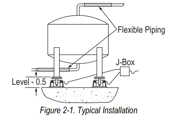
It is crucial that all piping (or conduit) is horizontal and flexible.![]() NOTE: If flexible piping is not used, ensure distance from the vessel to the first pipe support is 20-30 times pipe diameter. For details, see the Load Cell and Weigh Module Handbook (PN 22054).
NOTE: If flexible piping is not used, ensure distance from the vessel to the first pipe support is 20-30 times pipe diameter. For details, see the Load Cell and Weigh Module Handbook (PN 22054).
In smaller, lower capacity tanks and hoppers, isolating resultant forces is critical. Load cells should not be installed in mounts until welding is complete. The heat generated from welding currents passing through load cells can damage the adhesive holding the strain gauge to body.![]() NOTE: Use dummy load cells when welding to maintain finished height.
NOTE: Use dummy load cells when welding to maintain finished height.
If welding is unavoidable after load cell installation, connect the ground so the current does not flow through the load cell.
Example: If welding on the mount top plate, the ground must be connected to the vessel and not to the mount base or support structure. Protect the load cell and cable from weld splatter.![]() NOTE: Use hermetically sealed RL72019SS load cells in washdown applications.
NOTE: Use hermetically sealed RL72019SS load cells in washdown applications.![]() WARNING: Environmentally protected load cells are not suitable for such applications and will be damaged.
WARNING: Environmentally protected load cells are not suitable for such applications and will be damaged.
If tanks and surrounding equipment are frequently steam cleaned, or if the load cell is subjected to direct washdown, a protective shroud for the weighing assembly is recommended.
Proper drainage is necessary so the weighing assembly is not standing in water. All support points should be equally stiff so that they deflect by the same amount as the vessel is loaded. 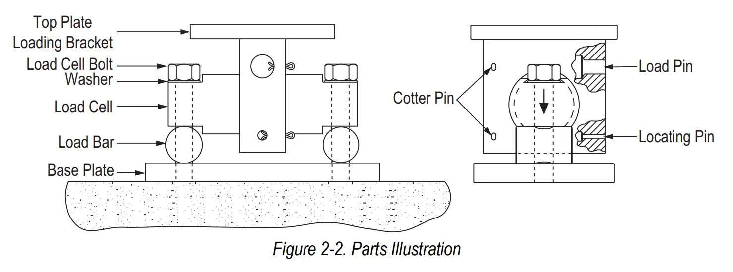
2.2 Installing the EZ Mount
The type of installation and strength of the mounting surface governs the method of locating, attaching, and assembling the EZ Mount assembly. Carefully consider three areas which commonly cause accuracy problems:
- Are supporting legs adequately braced so they will not spread when system is fully loaded?
- Does the supporting structure have the necessary strength to prevent excessive deflection when the system is fully loaded?
- Is there attached equipment such as skirting, venting, or piping which is likely to cause binding or lack of flexibility?
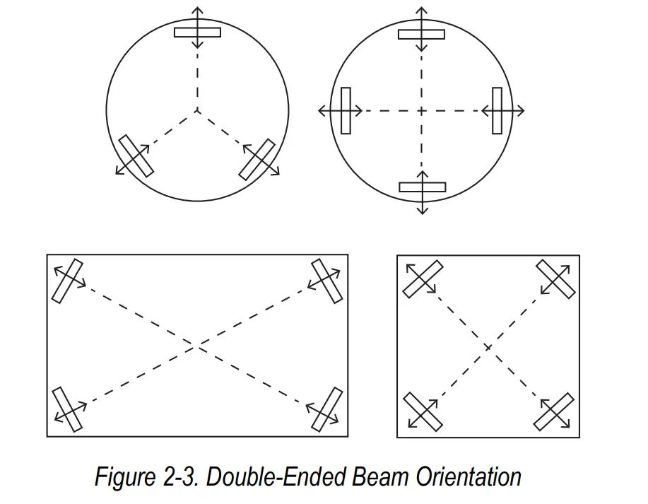
1. Determine where to position the mount and in which direction it should be oriented.
The EZ Mount is designed to allow for lateral movement in the direction perpendicular to the longitudinal axis of the load cell. These tank weighing units should be oriented so that the movement due to thermal expansion/contraction is perpendicular to the longitudinal axis. Sample mounting orientations to accommodate expansion for different vessel shapes are as follows: 2. Assemble the mounts by inserting either a dummy load cell or the actual load cell into the hole in the top plate loading bracket then installing the load pin and locating pin (Section 6.0 on page 14).
3. Pass the load cell bolts through the ends of the load cell and load bars and thread into the base plate. Tighten by hand. NOTE: The arrow on the load cell should point in the direction of the load.
4. Lift and block the vessel to the same height as the assembled mounts.
 2. Assemble the mounts by inserting either a dummy load cell or the actual load cell into the hole in the top plate loading bracket then installing the load pin and locating pin (Section 6.0 on page 14).
Load Cell Wiring
This section provides an overview of load cell wiring information.
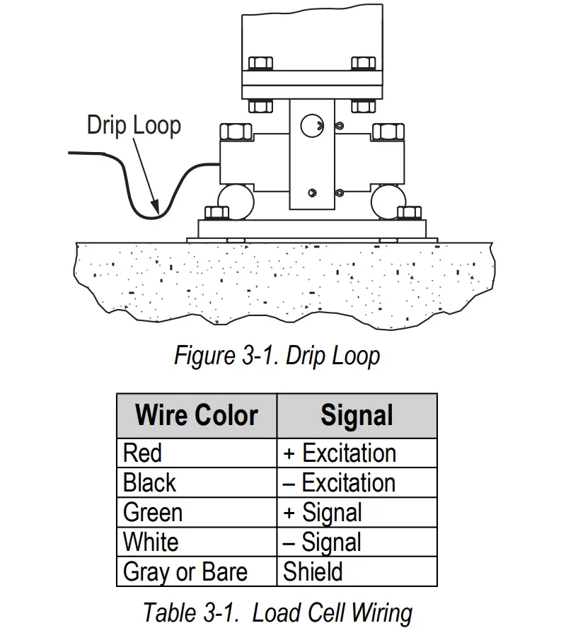
- Route the load cell cables so they will not be damaged or cut. Cable should not be routed near heat sources greater than 150°F. Do not shorten any load cell cable. The load cell is temperature compensated with the supplied length of cable. Cutting the cable will affect temperature compensation. Coil and protect excess cable so it will not be mechanically damaged or be sitting in water.
- Provide a drip loop in all cables so that water or other liquids will not run directly down the cables onto either the load cells or the junction box. Attach load cell cable to the dead structure, not to the vessel.NOTE: If conduit protection is necessary against mechanical or rodent damage to the load cell cables, use flexible conduit and conduit adapters at the load cells.
Conduit can also provide protection against moisture ingress into the load cell. - Connect cables for standard RL70000, RL70000SS, RTI 5103, RTI 9103 load cells or RL72019SS welded seal load cells to the summing board in the junction box according to the guide shown below and the labels on terminal strips of the junction box.NOTE: To verify the wiring scheme, see the certification shipped with each load cell.NOTE: For better performance, use positive and negative remote sense lines if the wiring running from the junction box to the indicator is longer than 25′.
Junction Box
See additional resources for device and junction box information.
NOTE: Manuals and additional resources are available on the Rice Lake Weighing Systems website at www.ricelake.com.
Additional information not included in this manual which may be required for proper device configuration may include material regarding connections, adjustments and calibration.
- Refer to the junction box manufacturers documentation for the junction box installed for trimming details
NOTE: Junction box installation details vary depending on model and manufacturer. - Refer to the Load Cell and Weigh Module Handbook (PN 22054) for system calibration details
Troubleshooting
Issues associated with load cells are often non-loadcell related. Ensure all parts of the device are properly connected and secured prior to troubleshooting:
- Check load cell mount for debris restricting load cell movement or debris between scale and structure.
- Check that tank/vessel and mounts are plumb, level, and square at critical areas.
- Check all piping and conduit for connections which restrict vessel movement.
NOTE: If check rods are used, loosen all connections to finger tight only for testing. - Check the load cell cables for damage.
- Check all electrical connections.
If the system can be calibrated but does not return to zero, loses calibration, or demonstrates non-linearity or non-repeatability, see Table 5-1 for troubleshooting information.
| Symptom | Possible Cause |
| Not returning to zero | Mechanical binding or debris in seals or under load cells; May have lost system calibration |
| Non-linearity | Thermal expansion or deflection under load causing binding or side load |
| Non-repeatability | Loose load cell mount; Drifting caused by moisture; Load cell overload or shack damage; Mechanical binding |
| Lost calibration | Out of level or plumb; Moisture problem; Mechanical binding |
| Drifting readout | Moisture in junction box, cables or load cells; Mechanical binding |
If issues persist:
- Check possible indicator malfunction by using a load cell simulator to input a known good signal into the indicator.
- Disconnect each load cell’s signal leads at the junction box and check individual load cell outputs with a multimeter then check input/output impedances for comparison with load cell manufacturer’s specifications.
If previous troubleshooting does not resolve the issue, see the following procedure:
1. Reconnect all but one load cell.
2. Replace the load cell with a load cell simulator. Alternate so that each load cell is individually disconnected and replaced with a simulator.
NOTE: If there is a problem with a particular load cell, the symptom should disappear when that load cell is disconnected and replaced with simulator.
Replacement Parts
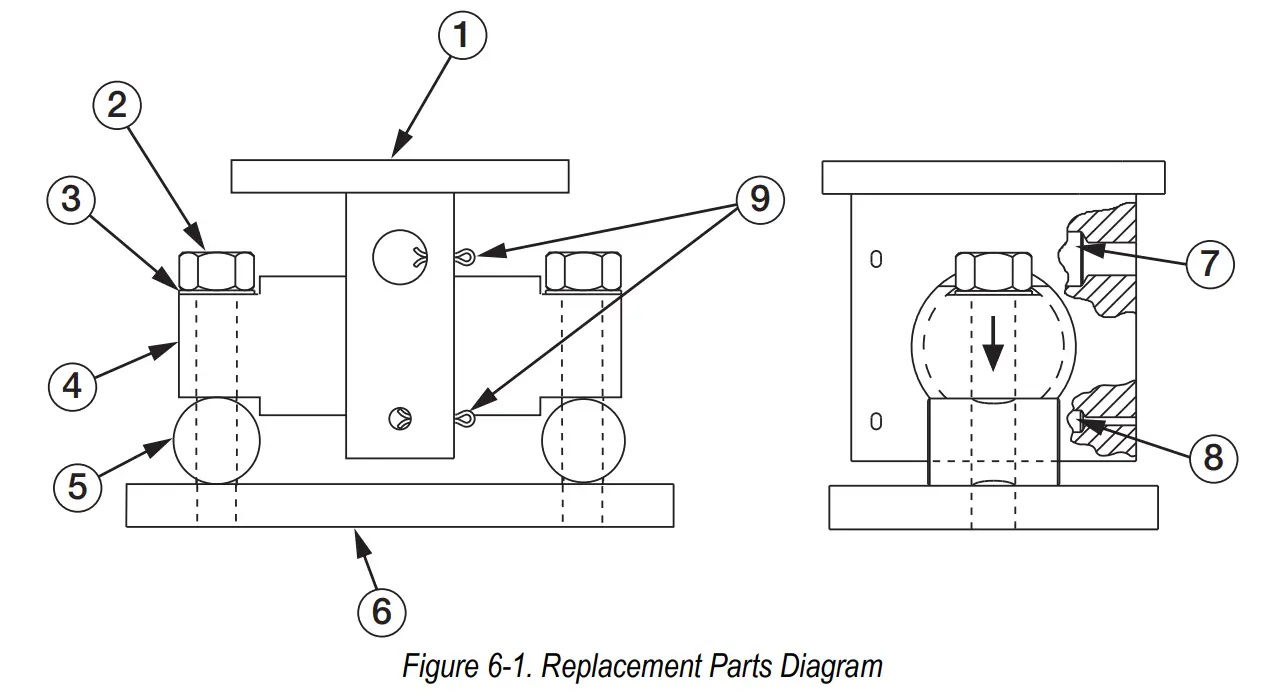
Mild Steel Mounts
| Item No. | Description | Qty. | Part No. | |||||
| 1 | Top Plate Loading Bracket | 1 | 18273 | 18274 | 18275 | 29014 | 26061 | |
| 2 | Load Cell Bolt | 2 | 14773 | 14795 | 14797 | 14797 | 26071 | |
| 3 | Washer | 6 | 15177 | 15184 | 15184 | 15184 | 26070 | |
| 4 | Double-Ended Shear Beam Load Cell | 1 | See Load Cell Selection Guide (PN 198058) | |||||
| 5 | Load Bar | 2 | 18267 | 18268 | 18269 | 18269 | 26073 | |
| 6 | Base Plate | 1 | 18264 | 18265 | 81266 | 82166 | 26074 | |
| 7 | Load Pin | 1 | 18270 | 18271 | 18272 | 18272 | 26067 | |
| 8 | Locating Pin | 1 | 18261 | 18262 | 18263 | 18263 | 26076 | |
| 9 | Cotter Pins | 2 | 15229 | 15251 | 15257 | 15257 | 26069 | |
| — | JB4SS Junction Box (30K to 250K Capacity Kits) | 1 | 107700 | |||||
Table 6-1. Mild Steel Mount Replacement Parts List
- A-size mounts use load cells with capacities from 5,000 lb – 20,000 lb.
- B-size mounts use load cells with capacities from 30,000 lb – 60,000 lb.
- C-size mounts use load cells with a capacity of 100,000 lb.
- D-size mounts use load cells with a capacity of 150,000 lb.
- E-size mounts use load cells with a capacity of 200,000 lb. and 250,000 lb.
Stainless Steel Mounts
| Item No. | Description | Qty. | Part No. | |||
| D* | ||||||
| 1 | Top Plate Loading Bracket | 1 | 18376 | 18377 | 18378 | 29013 |
| 2 | Load Cell Bolt | 2 | 14774 | 14796 | 14798 | 14798 |
| 3 | Washer | 6 | 15178 | 15187 | 15187 | 15187 |
| 4 | Double-Ended Shear Beam Load Cell | 1 | See Load Cell Selection Guide (PN 198058) | |||
| 5 | Load Bar | 2 | 18267 | 18268 | 18269 | 18269 |
| 6 | Base Plate | 1 | 18370 | 18371 | 18372 | 18372 |
| 7 | Load Pin | 1 | 18270 | 18271 | 18272 | 18272 |
| 8 | Locating Pin | 1 | 18373 | 18374 | 18375 | 18375 |
| 9 | Cotter Pins | 2 | 15230 | 15252 | 15258 | 15258 |
| — | JB4SS Junction Box (30K to 250K Capacity Kits) | 1 | 107700 | |||
Table 6-2. Stainless Steel Mount Replacement Parts List
- A-size mounts use load cells with capacities from 5,000 lb – 20,000 lb.
- B-size mounts use load cells with capacities from 30,000 lb – 60,000 lb.
- C-size mounts use load cells with a capacity of 100,000 lb.
- D-size mounts use load cells with a capacity of 150,000 lb.
- E-size mounts use load cells with a capacity of 200,000 lb. and 250,000 lb.
![]()
© Rice Lake Weighing Systems Content subject to change without notice.
230 W. Coleman St.
Rice Lake, WI 54868
USA
U.S. 800-472-6703
Canada/Mexico 800-321-6703
International 715-234-9171
Europe +31 (0)26 472 1319


 User Manual")


