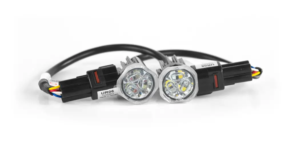
Cell2 UR06 LED Flush Mount Kit

CONTENTS

WIRING & FUNCTIONS
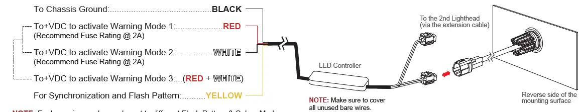
NOTE: Each warning mode may be set to different Flash Pattern & Colour Mode.
OPERATION
For Synchronization:
Connect ![]() wires of all lightheads together for synchronization. (All the lightheads should be set to the same Flash Pattern)
wires of all lightheads together for synchronization. (All the lightheads should be set to the same Flash Pattern)
For Warning Colour Mode:
Each Warning Mode ![]() may be set to warning or
may be set to warning or ![]() in ,
in , ![]()
![]() . To change Warning Colour Mode:
. To change Warning Colour Mode:
- Choose the desired warning mode to change and apply +VDC to its activation wire
 with
with  wire simultaneously to enter Setting Mode; lighthead will display short flashes in its current Colour Mode.
- Colour 1 (Warning Mode 1 Pre-set)
- Colour 2 (Warning Mode 2 Pre-set)
- Colour 1 alt. 2 (Warning Mode 3 Pre-set)
- Remove wire from +VDC and momentarily apply to +VDC again to change Colour Mode.
- Once in desired Colour Mode, save and Exit Setting Mode by powering off the lighthead.
For Flash Pattern:
While a warning mode is actiaved, momentarily apply +VDC to ![]() wire:
wire:
- once for next pattern
- quick three times to reset to FP#1 (see flash pattern chart)
| Flash Pattern | |||
| 1 | Double [2Hz] | 15 | Random |
| 2 | Single [2Hz] | 16 | Double [2Hz] (SPLIT) |
| 3 | Triple [2Hz] | 17 | Single [2Hz] (SPLIT) |
| 4 | Quad [2Hz] | 18 | Triple [2Hz] (SPLIT) |
| 5 | Single | 19 | Quad [2Hz] (SPLIT) |
| 6 | Double | 20 | Single (SPLIT) |
| 7 | Quad | 21 | Double (SPLIT) |
| 8 | Quint | 22 | Quad (SPLIT) |
| 9 | Mega | 23 | Quint (SPLIT) |
| 10 | Ultra | 24 | Mega (SPLIT) |
| 11 | Single-Quad | 25 | Ultra (SPLIT) |
| 12 | Single H/L | 26 | Single-Quad (SPLIT) |
| 13 | Steady EF * | 27 | Single H/L (SPLIT) |
| 14 | Steady Scene | ||
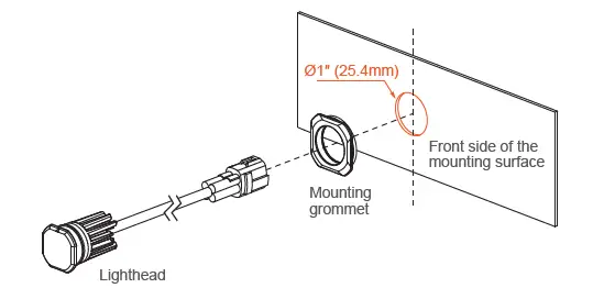
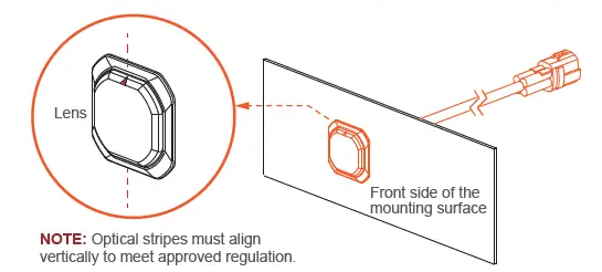
INSTALLATION – FLUSH MOUNT
- Select a mounting location and drill one 1″ (25.4mm) cut-out.
NOTE: Mounting surface thickness @ 0.8~2.0mm
- From the front, install MOUNTING GROMMET onto the cut-out, and then insert the LIGHTHEAD.

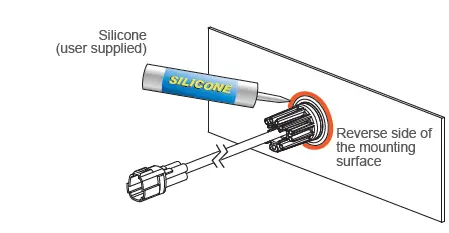
- Where necessary, apply silicone around the reverse side to prevent from rotating.

- Where necessary, apply silicone around the reverse side to prevent from rotating.

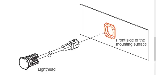
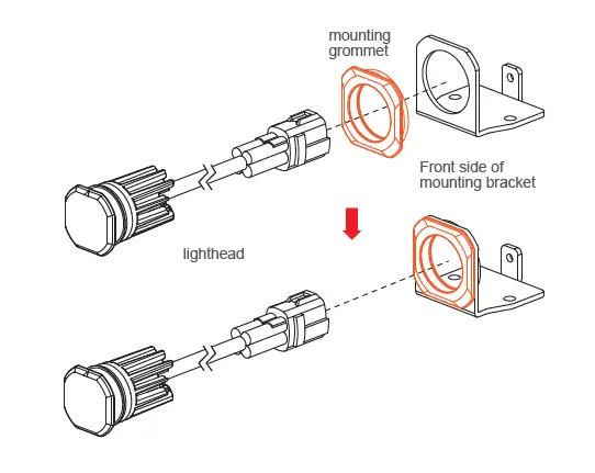
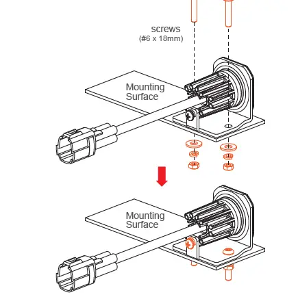
INSTALLATION – BRACKET MOUNT (sold-separately)
- From the front, install the MOUNTING GROMMET onto the BRACKET, and insert the LIGHTHEAD.

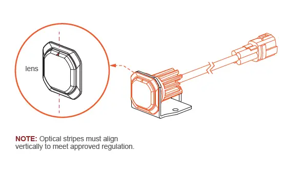
- Ensure that triangle mark on the lens is aligned vertically.

- Secure the LIGHTHEAD onto the BRACKET with a screw.
- Secure the BRACKET onto the desired mounting surface with screws.


WIRING 2 KITS TOGETHER
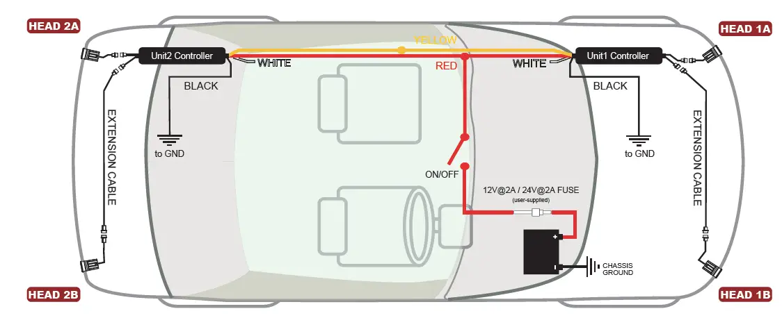
Below is a schematic diagram for wiring 2 kits together.
Yellow wires from both controllers must be connected together for synchronization.
- When Flash Pattern 1~12 is selected: All Heads will flash simultaneously.
- When Flash Pattern 15~26 is selected: Head 1A&2A will flash alternatively with Head 1B&2B.
* refer to Flash Pattern chart on opposite page.
NOTE: To have Head 1A&2B alternate with 1B&2A, simply reverse the lightheaded outlets on one of the Controllers; (both kits must be in Flash Pattern 15~26).
NOTE: The mounting area for controllers varies from vehicle to vehicle.


