
![]() UR04 Led Flush Mount Kit
UR04 Led Flush Mount Kit
User Guide
CONTENTS

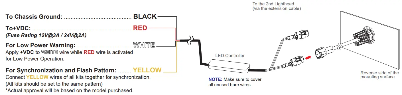
WIRING & FUNCTIONS
OPERATION
For Simultaneous or Alternating Synchronization:
- Apply +VDC to RED and YELLOW wires simultaneously to enter Flash Mode Selection.
- Remove YELLOW wire from +VDC and momentarily apply to +VDC to change mode selection:
Mode 1 = Head 1 & 2 flash alternately
Mode 2 = Head 1 & 2 flash simultaneously - Exit Flash Mode Selection by removing +VDC.
For Flash Pattern Selection:
Momentarily apply +VDC to YELLOW wire
Once to next pattern
Quick three times to FP#1 (see Flash Pattern Chart)
| FP# | Flash Patterns | ||
| 1 | Single [2Hz] | 8 | Quad |
| 2 | Double [R65]* | 9 | Quint |
| 3 | Triple [2Hz] | 10 | Mega |
| 4 | Quad [2Hz] | 11 | Ultra |
| 5 | Random | 12 | Single-Quad |
| 6 | Single | 13 | Single H/L |
| 7 | Double | 14 | Steady or Steady Double** |
* Actual approval will be based on the model purchased.
** In Mode 2, lightheads will both steady-burn; in Mode 1, one lighthead will steady burn while the other does double flash.
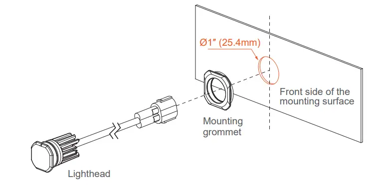
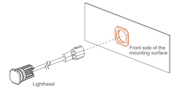
INSTALLATION – FLUSH MOUNT
- Select a mounting location and drill one 1″ (25.4mm) cut-out.
NOTE: Mounting surface thickness @ 0.8~2.0mm
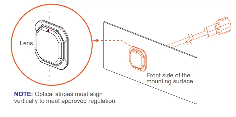
- From the front, install MOUNTING GROMMET onto the cut-out, and then insert the LIGHTHEAD.

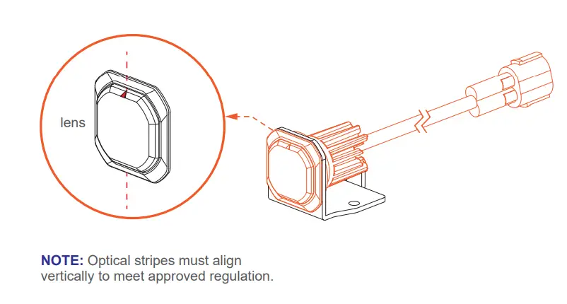
- Ensure that triangle mark on the lens is aligned vertically.

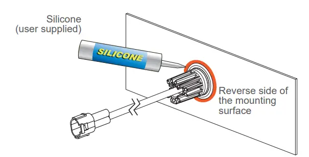
- Where necessary, apply silicone around the reverse side to prevent from rotating.

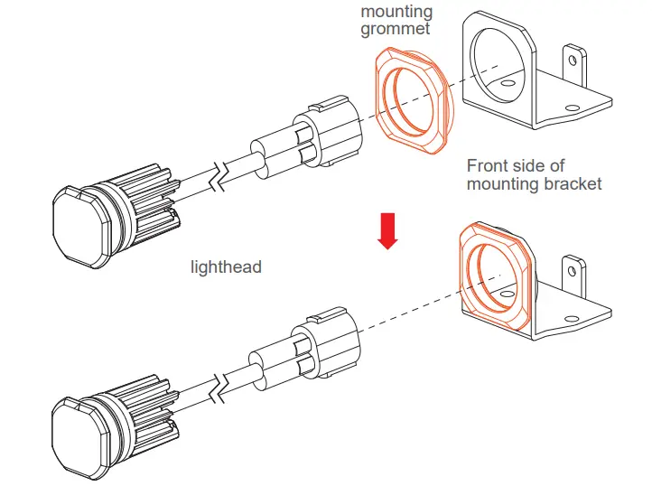
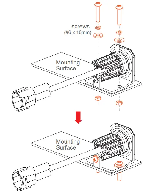
INSTALLATION – BRACKET MOUNT (sold-separately)
- From the front, install the MOUNTING GROMMET onto the BRACKET, and insert the LIGHTHEAD.

- Ensure that triangle mark on the lens is aligned vertically.

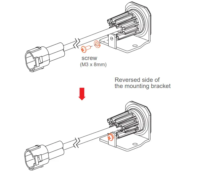
- Secure the LIGHTHEAD onto the BRACKET with a screw.

- Secure the BRACKET onto the desired mounting surface with screws.

WIRING 2 KITS TOGETHER
Below is a schematic diagram for wiring 2 kits together.
YELLOW wires from both controllers must be connected together for synchronization.
- If Mode 1 is selected: Head 1A&2A will flash alternately with Head 1B&2B.
- If Mode 2 is selected: All Heads will flash simultaneously.
* Refer to Flash Pattern Chart on the opposite page.
NOTE: To have Head 1A&2B alternate with 1B&2A, simply reverse the lighthead outlets on one of the Controllers; (both kits must be in Mode 1).
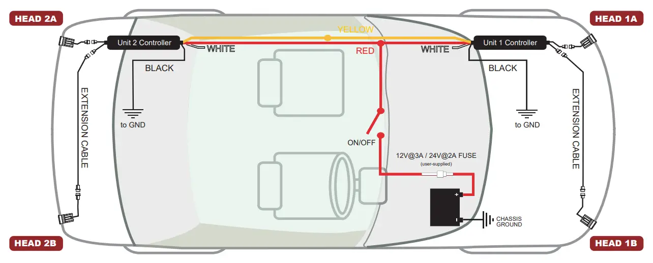
NOTE: The mounting area varies from vehicle to vehicle. (The diagram is not drawn to scale)


