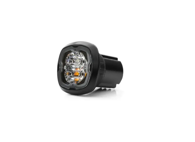
Cell2 CR06-DC Led Flush Mount Kit
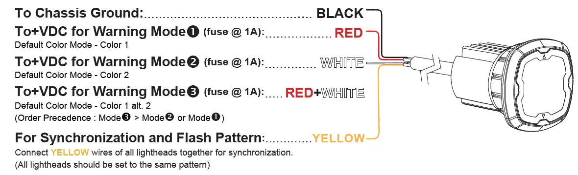
WIRING
OPERATION
For Flash Pattern Selection
While in Warning Mode, momentarily apply +VDC to YELLOW wire:
- once to next pattern
- quickly three times to FP#1 (Refer ro Flash Pattern Chart)
For Simultaneous or Alternating Flash
- Apply +VDC to RED and YELLOW wires simultaneously to enter SETTING MODE; lighthead will display short (single or double) flashes:
- Single flash = Group 1
- Double flash = Group 2
- Remove YELLOW wire from +VDC then momentarily apply +VDC again for more than 3 seconds to change Groups.
- Lightheads of the same Group will flash together.
- Lightheads of different Groups will flash alternately.
- Save and Exit the SETTING MODE by powering off the lighthead.
NOTE: All warning memories share the same Group setting.
For Color Mode Setting
- Apply +VDC to RED and YELLOW wires simultaneously to enter SETTING MODE; lighthead will display short (single or double) flashes:
- Single Color flashing Color 1 = Color1
- Single Color flashing Color 2 = Color2
- Dual Color flashing Color 1 = Color1 alt 2
- Dual Color flashing Color 2 = Color2 alt 1
- Remove YELLOW wire from +VDC then momentarily apply +VDC again for less than 3 seconds to change Color Mode.
- Save and Exit the SETTING MODE by powering off the lighthead.
Reset to Factory Default Settings
- Apply +VDC to RED and YELLOW wires simultaneously to enter SETTING MODE
- Remove YELLOW wire from +VDC then momentarily apply to +VDC again more than 5 seconds.
The lighthead will display fast shrot flashers to signify restoring successfully. - Save and Exit the SETTING MODE by powering off the lighthead
Flash Pattern 1 Double [R65*] 8 Double [SAE] 15 Single-Quad 22 Triple-Triple Fast 2 Single [2Hz] 9 Triple [SAE] 16 Single H/L 23 Quint-Triple 3 Triple [2Hz] 10 Quad [SAE] 17 Single-Triple-Quint 24 7-1 Flash 4 Quad [2Hz] 11 Quint [SAE] 18 Steady Scene 25 7-1 Flash # 5 Random 12 Mega 19 Single-Single 26 Quad-Single 6 Steady EF** 13 Giga 20 Double-Double 27 Quad-Single# 7 Single [SAE][CA13] 14 Ultra [SAE] 21 Triple-Triple Mid 28 Quint-Quint
FP19~28 will aways operate in dual color.
Inverted color mode.
Actual approval will be based on the model ordered.
For use with external flash controller
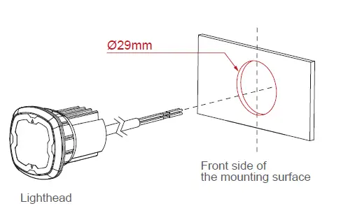
INSTALLATION
Pop-n-Lock
Recommended Surface thickness @1.5~4.0mm
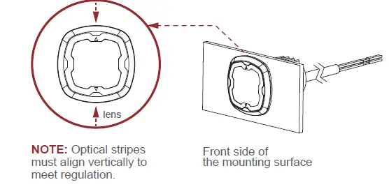
- Select a mounting location and drill an 1.14” (29mm) cut-out, and then install the LIGHTHEAD onto the cut-out.

NOTE: To install more efficiently, use a rotating motion to guide the LIGHTHEAD when installing onto the cut-out. - Ensure that the optical stripes are aligned vertically

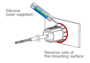
- Where necessary, apply silicone around the reverse side to prevent from rotating

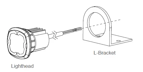
Bracket Mount
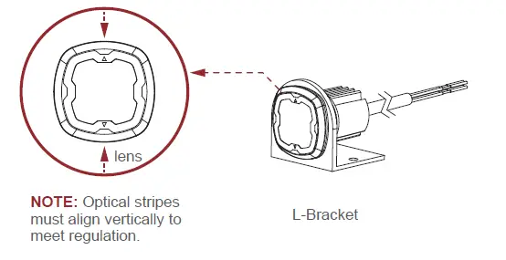
- From the front, install the LIGHTHEAD onto the BRACKET.

- Ensure that the optical stripes are aligned vertically.

NOTE: To install more efficiently, use a rotating motion to guide the LIGHTHEAD when installing onto the BRACKET.
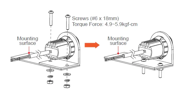
Secure the BRACKET onto the desired mounting surface with screws.: To install more efficiently, use a rotating motion to guide the LIGHTHEAD when installing onto the BRACKET. - Secure the BRACKET onto the desired mounting surface with screws.

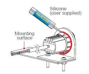
- Where necessary, apply silicone around the reverse side to prevent from rotating.