
![]() RAYZR Lighthead 3LED TIR
RAYZR Lighthead 3LED TIR
User Manual
RAYZR Lighthead 3LED TIR
WIRING FOR WARNING STICKS
RED ……………………[+] Warning Mode to +VDC with rated fuse (for correct rating, refer to the Fuse Rating Chart)
BLACK …………………to Chassis ground
| Fuse Rating | |
| 2-Head Model = 2 Amps | 4-Head Model = 3 Amps |
YELLOW………………. [+] Flash Pattern Selection (refer to Flash Patterns chart) / Synchronization Momentarily apply +VDC to YELLOW wire:
- Once to next pattern
- Quick 3 times to FP#1
Connect YELLOW wires of all sticks together for synchronization* *All sticks should be set to the same pattern
WHOTE …………………………..[+] for Simultaneous or Alternating Flash (for multi-sticks only)
Group1 – Sticks with WHOTE connected to +VDC will flash together
Group2 – Sticks with WHOTE not connected to +VDC will flash together
Group1 will alternate with Group2
| Warning Stick Flash Patterns | |||||
| 1 | Kit Scan | 10 | [Left-Right] Single | 19 | [All] Quint |
| 2 | Kit Scan + Double | 11 | [Left-Right] Double 2Hz | 20 | [Ali] Ultra |
| 3 | [wig-wag] Slow-Fast | 12 | [Left-Right] Quint | 21 | rem Single-Quad |
| 4 | [Outside-In] Single | 13 | [Left-Right] Ultra | 22 | [All] Single H/L |
| 5 | (Outside-In] Ultra | 14 | [Left-Right] Single-Quad | 23 | [All] Quint + (Left-eight] Mega |
| 6 | [Side-by-Side] Single | 15 | (Left-Right] Single H/L | 24 | [Half] Steady Half |
| 7 | [SIde-by-Side] Ultra | 16 | [Left-Right] Quint + [All] Mega | 25 | [Ali] Steady All |
| 8 | [Side-by-Side] Slow-Fast | 17 | [All) Single | 26 | Left Chaser |
| 9 | Random | 18 | [All) Double 2Hz | 27 | Right Chaser |
WIRING FOR TRAFFIC ADVISOR WARNING STICK
RED ………………..to +VDC with rated fuse (for correct rating, refer to the Fuse Rating Chart)
BLACK …………………….to Chassis ground
Fuse Rating
6-Head Model = 4 Amps
10-Head Model = 7 Amps
8-Head Model = 6 Amps
| BLUE……………………. [+] Rear “Left Arrow” [122] | Rear”Centre Out Arrow” [P1] |
| ORANGE……………… [+] Rear “Right Arrow” [P2] |
BROWN……………. [+] Warning Mode [P3]
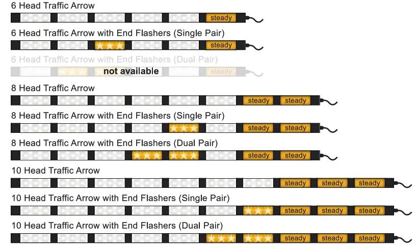
GREEN …………….[+] Low Power Operation or [+] End-Flasher* *See “Firmware Selection” for End-Flasher Mode.
| End Flasher Patterns (Green) | |
| 1 | Double [2Hz] (all) |
| 2 | Quad [2Hz] (all) |
| 3 | Single [2Hz] (all) |
| 4 | Double [2Hz] (split) |
| 5 | Quad [2Hz] (split) |
| 6 | Single [2Hz] (split) |
WHITE………….. [ ] Control Panel Indicator Signal out (connect to a compatible Control Panel)
YELLOW…………….. [+] Flash Pattern Selection (refer to respective pattern chart) While End-Flasher, Traffic Advising or Warning Mode is activated, Momentarily apply +VDC to YELLOW wire:
- Once to next pattern
- Quick 3 times to FP#1
NOTE: [Px] = Precedence order, when more than a wire is activated at the same time, higher priority wire will affect lower priority wire. P1 being the highest priority.
End Flasher Patterns (Green) 1 Double [2Hz] (all) 2 Quad [2Hz] (all) 3 Single [2Hz] (all) 4 Double [2Hz] (split) 5 Quad [2Hz] (split) 6 Single [2Hz] (split)
| Traffic Advisor Warning Stick Patterns (Brown) | |||
| 1 | Random / Custom | 11 | [Wig-wag] Slow-Fast |
| 2 | Random Standard | 12 | [Left-Right] Single |
| 3 | [Outside-In] Single | 13 | [Left-Right] Ultra |
| 4 | [Outside-In] Ultra | 14 | [Left-Right] Single H/L |
| 5 | [Side-by-Side] Single | 15 | [Left-Right] Quint + [All] Mega |
| 6 | [Side-by-Side] Ultra | 16 | [All] Single |
| 7 | [Side-by-Side] Slow-Fast | 17 | [All] Double |
| 8 | Kit Scan | 18 | [All] Ultra |
| 9 | Kit Scan Split | 19 | [All] Quint + [Left-Right] Mega |
| 10 | Kit Scan Dual + Double | 20 | [All] Steady |
| Arrow Patterns (Orange / Blue) | |
| 1 | Sweep Single |
| 2 | Sweep Double |
| 3 | Sweep Triple |
| 4 | Sweep Single End x2 |
| 5 | Solid |
| 6 | Solid End x2 |
| 7 | Solid Chaser |
| 8 | Solid Fade |
| 9 | Blink Double |
| 10 | Blink Triple |
| 11 | Blink Solid |
FIRMWARE SELECTION FOR TRAFFIC ADVISOR WARNING STICK
All Traffic Advisor Warning Stick come with built-in selectable firmwares. To change firmware:
- Apply +VDC to RED, = and GREEN wires simultaneously then remove GREEN wire from +VDC to enter FIRMWARE selection.
- Once in FIRMWARE selection mode, the unit will display one of the following patterns.

- Momentarily apply GREEN wire to +VDC to change FIRMWARE. 4. Once a desired FIRMWARE is selected, save and exit by disconnect all power.
CUSTOM PATTERN PROGRAMMING FOR TRAFFIC ADVISOR WARNING STICK
PROGRAMMING FP#1 Random Custom pattern from Warning Patterns can be customized. This can only be done through firmware that is set to Traffic Arrow.
To configure FP#1 flash pattern:
- Activate Warning Patterns by applying +VDC to BROWN wire.
- Scroll to flash pattern FP#1 by quickly tapping +VDC 3 times to YELLOW wire .
- Enter PROGRAMMING by quickly tapping +VDC 3 times to GREEN wire.
- Once in PROGRAMMING, all lightheads will faintly blink once every second. The center pair of lightheads will be activated.
- Tap +VDC to YELLOW wire:
• Once for next pattern (see Lighthead Pattern Chart).
• Quick 3 times for FP#1. - Scroll to the next pair of lightheads by tapping +VDC to GREEN wire.
- Repeat steps 5 and 6 until all lightheads are properly configured.
- Exit PROGRAMMING by quickly tapping +VDC 3 times to GREEN wire or disconnect all power.
RESETTING
To restore factory setting:
- Apply +VDC to RED, YELLOW, and GREEN wires simultaneously for more than 3 seconds and remove GREEN wire from +VDC to enter FIRMWARE selection.
- Once in FIRMWARE selection mode, momentarily apply GREEN wire to +VDC for more than 3 seconds to reset. All lightheads will blink once to indicate the reset.
- Save and exit by disconnect all power.
| Programmable Lighthead Pattern | ||
| 1 | Steady | (All) |
| 2 | Single Slow | (Left-Right Split) |
| 3 | Single Mid | (Left-Right Split) |
| 4 | Single Fast | (Left-Right Split) |
| 5 | Double 2Hz | (Left-Right Split) |
| 6 | Double | (Left-Right Split) |
| 7 | Qoad 2Hz | (Left-Right Split) |
| 8 | Ultra | (Left-Right Split) |
| 9 | Single-Quad | (Left-Right Split) |
| 10 | Single H/L | (Left-Right Split) |
| 11 | Random | (All) |
| 12 | Off | |
| 13 | Single Slow | (All) |
| 14 | Single Mid | (All) |
| 15 | Single Fast | (All) |
| 16 | Double 2Hz | (All) |
| 17 | Double | (All) |
| 18 | Qoad 2Hz | (All) |
| 19 | Ultra | (All) |
| 20 | Single-Quad | (All) |
| 21 | Single H/L | (All) |
![]()


