
![]()
ID26 Mini Light Head
Instruction Manual 170221M41-2
ID26 Mini Light Head
Surface Mount
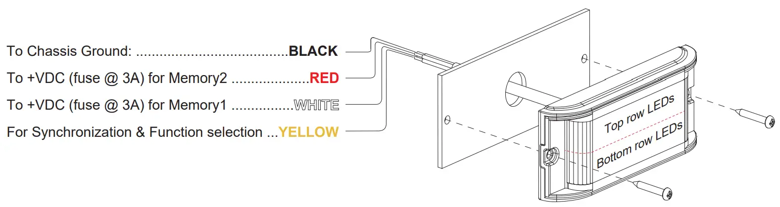
NOTE: RED wire has priority over WHITE wire when both wires are activated.
Operation
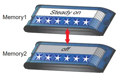
This lightheaded is designed with 2 sets of memory to allow instant switch between 2 pre-set flash patterns with a simple switch of a button (user-supplied). Connect BLACK wire to Ground, and apply +VDC to WHITE wire to activate Memory1 or to RED wire to activate Memory2.
Step 1
Select Function & Flash Pattern
a. Activate Memory1 by applying +VDC to WHITE wire.
b. While WHITE wire is activated, momentarily apply +VDC to YELLOW wire:
• once for <1 second for next flash pattern.
• quickly three times for reset to default.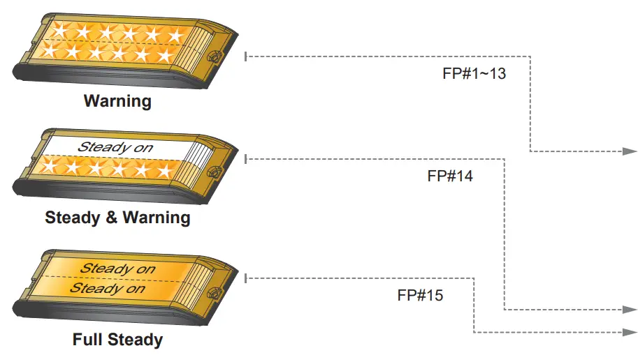
| Function | FP# | Flash Pattern | |
| Warning | 1 | Double (default) | R65 |
| 2 | Single | 2Hz | |
| 3 | Triple | 2Hz | |
| 4 | Quad | 2Hz | |
| 5 | Random | – | |
| 6 | Single | SAE | |
| 7 | Double | SAE | |
| 8 | Quad | SAE | |
| 9 | Quint | SAE | |
| 10 | Mega | – | |
| 11 | Ultra | SAE | |
| 12 | Single-Quad | – | |
| 13 | Single H/L | – | |
| Steady & Warning | 14 | Steady& Warning | – |
| Full Steady | 15 | Full Steady | – |
Step 2
Select Mode
a. While WHITE wire is activated, apply +VDC to YELLOW wire for >3 seconds to enter Mode setting.
b. Once in Mode setting, lightheaded will display dim slow pulses based on its Mode and Group (single or double pulses respectively).
c. Momentarily apply +VDC to YELLOW wire for <1 second for next Mode. (refer to Mode charts).
d. Momentarily apply +VDC to YELLOW wire quickly 3 times within 1 second to reset to Mode1.
e. When desired mode is selected, apply +VDC to YELLOW for >3 seconds or disconnect all power to exit Mode setting.
f. To configure Memory2, apply +VDC to RED wire and repeat the above steps A & B.
NOTE:
For multiple lightheaded installation, heads in the same Group flash together. [G1] Heads alternate with [G2] Heads. For synchronization all YELLOW wires must be connected together, and set at the same Flash Pattern.
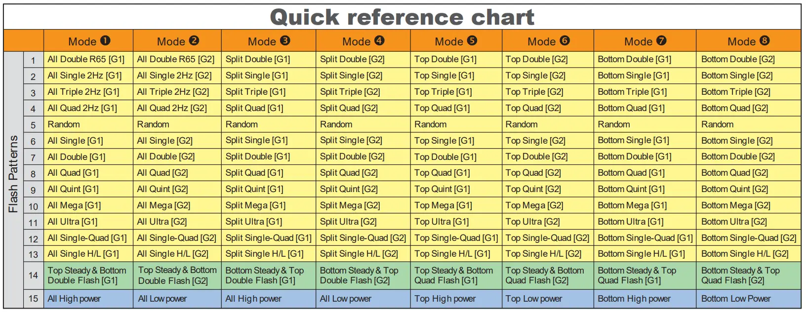
| Mode | Warning Effect | |
| 1 | All (single pulse) | All [G1] |
| 2 | All (double pulse) | All [G2] |
| 3 | Split (single pulse) | Split [G1] |
| 4 | Split (double pulse) | Split [G2] |
| 5 | Top (single pulse) | Top only [G1] |
| 6 | Top (double pulse) | Top only [G2] |
| 7 | Bottom (single pulse) | Bottom only [G1] |
| 8 | Bottom (double pulse) | Bottom only [G2] |
All = Top & Bottom simultaneous
Split = Top & Bottom alternating
[G1] = Group1 [G2] = Group2

| Mode | Steady & Warning Effect | |
| 1 | All (single pulse) | Top Steady & Bottom Double Flash [G1] |
| 2 | All (double pulse) | Top Steady & Bottom Double Flash [G2] |
| 3 | Split (single pulse) | Bottom Steady & Top Double Flash [G1] |
| 4 | Split (double pulse) | Bottom Steady & Top Double Flash [G2] |
| 5 | Top (single pulse) | Top Steady & Bottom Quad Flash [G1] |
| 6 | Top (double pulse) | Top Steady & Bottom Quad Flash [G2] |
| 7 | Bottom (single pulse) | Bottom Steady & Top Quad Flash [G1] |
| 8 | Bottom (double pulse) | Bottom Steady & Top Quad Flash [G2] |
[G1] = Group1 [G2] = Group2
All = Top & Bottom simultaneous
Split = Top & Bottom alternating

| Mode | Full Steady Effect | |
| 1 | All (single pulse) | All high power |
| 2 | All (double pulse) | All low power |
| 3 | Split (single pulse) | All high power |
| 4 | Split (double pulse) | All low power |
| 5 | Top (single pulse) | Top high power |
| 6 | Top (double pulse) | Top low power |
| 7 | Bottom (single pulse) | Bottom high power |
| 8 | Bottom (double pulse) | Bottom low power |
All = Top & Bottom simultaneous
Split = Top & Bottom alternating
Examples
Example Configuration#1:
I would like Memory1 to be Full Steady (All low power), and Memory2 to be split Ultra flash (Top row LEDs alternate Bottom row LEDs).
- Activate WHITE wire and select FP#15.
- Enter Mode setting and select Mode#2.
- Activate RED wire and select FP#11.
- Enter Mode setting and select Mode#3 (or Mode#4).


Example Configuration#2:
I would like Memory1 to be Top Steady & Bottom Double Flash, and Memory2 to be All Ultra flash.
- Activate WHITE wire and select FP#14.
- Enter Mode setting and select Mode#1 (or Mode#2).
- Activate RED wire and select FP#11.
- Enter Mode setting and select Mode#1 (or Mode#2).
 [G1] = Group1 [G2] = Group2
![]()


