86-M07710-0001.0
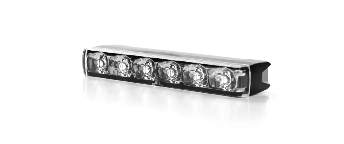
DUAL COLOUR 3+3 LED DUAL COLOUR LIGHTHEAD
WIRING
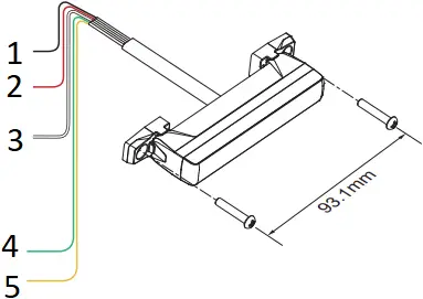
- To Chassis Ground:……………………………….. BLACK
- To+VDC for Warning Mode (1) (fuse @ 1A):……… RED
Default Colour Mode – Colour 1 - To+VDC for Warning Mode (2) (fuse @ 1A):….. WHITE
Default Colour Mode – Colour 2
(To+VDC for Warning Mode (3):………..RED+WHITE)
Default Colour Mode – Colour 1 alt. 2
Order of Precedence: Mode (3) > Mode (1) = Mode (2) > Cruise Mode - To+VDC for Cruise Mode (fuse @ 1A):……….. GREEN
- For Synchronization and Flash Pattern:…YELLOW
Connect YELLOW wires of all lightheads together for synchronization.
(All lightheads should be set to the same Flash Pattern)
OPERATION
For Flash Pattern Selection:
Each Warning Mode may select and save one Flash Pattern. While activating a Warning Mode, momentarily apply YELLOW wire to +VDC:
- Once to next pattern.
- Quick three times to the default Flash Pattern (FP#1).
(refer to Flash Pattern Chart)
For Simultaneous or Alternating Synchronization:
- Apply +VDC to RED (or WHITE or RED+WHITE) and YELLOW wires simultaneously to enter SETTING MODE; the lighthead will display short flashes:
• Single flash = Group 1 • Double flash = Group 2 - Remove YELLOW wire from +VDC then momentarily apply to +VDC again for more than 3 seconds to change Groups:
• Lightheads of the same Group will flash together.
• Lightheads of the different Group will flash alternately. - Save and exit SETTING MODE by disconnecting all power.
NOTE: All warning modes share the same Group setting.
For Color Mode Setting:
- Each Warning Memory may select and save one Colour Mode. Apply +VDC to RED (or WHITE or RED+WHITE) and YELLOW wires simultaneously to enter SETTING MODE; the lighthead will display its current Colour Mode:
• Single Colour flashing Color 1 = Color 1
• Single Colour flashing Color 2 = Color 2
• Dual Colour flashing Color 1 = Color 1 alt. 2
• Dual Colour flashing Color 2 = Color 2 alt. 1 - Remove YELLOW wire from +VDC then momentarily apply to +VDC for less than 3 seconds to change Colour Mode.
- Save and exit SETTING MODE by disconnecting all power.
Reset to Factory Default Settings:
- Apply +VDC to RED (or WHITE or RED+WHITE) and YELLOW wires simultaneously to enter SETTING MODE;
- Remove YELLOW wire from +VDC then momentarily apply to +VDC again for more than 5 seconds. The lighthead will display fast short flashes to signify restoring successfully.
- Save and exit SETTING MODE by disconnecting all power.
Flash Pattern (Dual Colour) | |||||||
1 | Double [2Hz] | 8 | Double [SAE] | 15 | Single-Quad | 22 | Triple-Triple Fast |
2 | Single [2Hz] | 9 | Triple [SAE] | 16 | Single H/L | 23 | Quint-Triple |
3 | Triple [2Hz] | 10 | Quad [SAE] | 17 | Single-Triple-Quint | 24 | 7-1 Flash |
4 | Quad [2Hz] | 11 | Quint [SAE] | 18 | Steady Scene | 25 | 7-1 Flash # |
5 | Random | 12 | Mega | 19 | Single-Single | 26 | Quad-Single |
6 | Steady EF* | 13 | Giga | 20 | Double-Double | 27 | Quad-Single# |
7 | Single [SAE][CA13] | 14 | Ultra [SAE] | 21 | Triple-Triple Mid | 28 | Quint-Quint |
FP#19~28 will always operate in dual colour.
* For use with external flash controller. # Inverted colour mode.
SINGLE COLOUR 6 LED SINGLE COLOUR LIGHTHEAD
WIRING
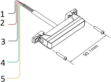
- To Chassis Ground:…………………………………. BLACK
- To+VDC for Warning Mode (fuse @ 2A):…………… RED
Apply +VDC to RED wire for High Power Operation (100%). - For Low Power Operation:………………………… WHITE
Apply +VDC to WHITE wire while RED wire is activated for Low Power Operation (40%). - To+VDC for Cruise Mode (fuse @ 2A):………… GREEN
Order of Precedence: Warning Mode > Cruise Mode - For Synchronization and Flash Pattern:….YELLOW
Connect YELLOW wires of all lightheads together for synchronization.
(All lightheads should be set to the same Flash Pattern)
OPERATION
For Flash Pattern Selection:
Each Warning Mode may select and save one Flash Pattern. While activating a Warning Mode, momentarily apply YELLOW wire to +VDC:
- Once to next pattern.
- Quick three times to the default Flash Pattern (FP#1).
(refer to Flash Pattern Chart)
For Simultaneous or Alternating Synchronization:
- Apply +VDC to RED and YELLOW wires simultaneously to enter SETTING MODE; the lighthead will display short flashes:
• Single flash = Group 1
• Double flash = Group 2 - Remove YELLOW wire from +VDC then momentarily apply to +VDC again for more than 3 seconds to change Groups:
• Lightheads of the same Group will flash together.
• Lightheads of the different Group will flash alternately. - Save and exit SETTING MODE by disconnecting all power.
Reset to Factory Default Settings:
- Apply +VDC to RED and YELLOW wires simultaneously to enter SETTING MODE;
- Remove YELLOW wire from +VDC then momentarily apply to +VDC again for more than 5 seconds. The lighthead will display fast short flashes to signify restoring successfully.
- Save and exit SETTING MODE by disconnecting all power.
Flash Pattern (Single Colour) | |||
1 | Double [2Hz] | 10 | Quad [SAE] |
2 | Single [2Hz] | 11 | Quint [SAE] |
3 | Triple [2Hz] | 12 | Mega |
4 | Quad [2Hz] | 13 | Giga |
5 | Random | 14 | Ultra [SAE] |
6 | Steady EF* | 15 | Single-Quad |
7 | Single [SAE][CA13] | 16 | Single H/L |
8 | Double [SAE] | 17 | Single-Triple-Quint |
9 | Triple [SAE] | 18 | Steady Scene |
* For use with external flash controller.
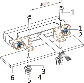
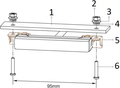
INSTALLATION
Universal Bracket (Multi-Angle)
NOTE:
Tighten the mounting bolts with the suggested range of torque value: 7.5~15 kgf-cm (6.5~13 lbf-in).
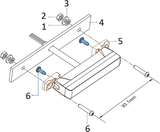
- Spring Washer
- Hex Nut
- Flat Washer
- Mounting Surface
- Universal Bracket
- Mounting Bolt
OR
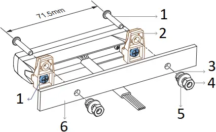
- Mounting Bolt
- Universal Bracket
- Spring Washer
- Hex Nut
- Flat Washer
- Mounting Surface
Adjustable Bracket (Optional)
The angle of lighthead is adjustable up to 20 degree for optimum warning efficiency.
Case (1)
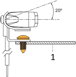
- Mounting Surface
OR
Case (2)
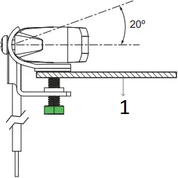
- Mounting Surface
NOTE:
Tighten the mounting bolts with the suggested range of torque value: 7.5~15 kgf-cm (6.5~13 lbf-in).
NOTE:
Apply the blackout tapes to avoid back-flash.
- Case (1): Mounting Screw
- Case (1): Toothed Washer
- Blackout Tape
- Case (2): Hex Bolt
- Foam Tape
- Adjustable Bracket
- Mounting Bolt
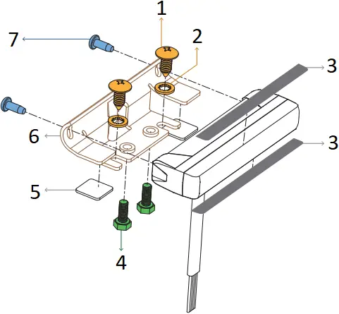
L-Bracket (Front / Rear)
NOTE:
Tighten the mounting bolts with the suggested range of torque value: 7.5~15 kgf-cm (6.5~13 lbf-in).
- Mounting Bolt
- L-Bracket
- Spring Washer
- Flat Washer
- Hex Nut
- Mounting Surface
OR
- Mounting surface
- Hex Nut
- Flat Washer
- Spring Washer
- L-Bracket
- Mounting Bolt


