
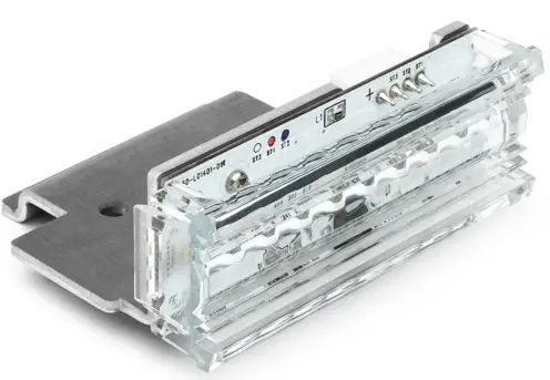
Cell2 Kuiper Lighthead Middle Linear 3LED
Operation Manual
WIRING & FUNCTIONS (L1)
Proper installation of the product requires the installer to have a good understanding of automotive electronics, systems and procedures. Different applications may require different functions. For optimum efficiency, it is highly recommended to determine, configure and test the required functions prior to Installation.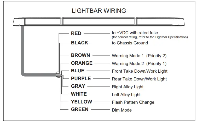
WIRING
- Route power cable’s red wire to a fused Install a fuse (user-supplied) on the end of power cable’s RED wire and route that wire to vehicle battery. Connect the BLACK wire to the vehicle chassis ground.
NOTE: Follow factory wiring harness through the firewall. It may be necessary to drill a hole in the firewall. Ensure that there is no component that could be damaged from the drilling. - Route control wires towards the dash area to a switch panel (user-supplied). Connect the required wires to the switch panel.
NOTE: Make sure that all wires of power cable are securely connected to power source.
WARNING
- DO NOT USE THE POWER WIRE(S) AS THE LIGHTBAR ACTIVATION SWITCH. USE ONLY THE FUNCTION WIRE(S) TO SWITCH AND ACTIVATE.
- FAULTY CONNECTIONS MAY CAUSE THE LIGHTBAR TO MALFUNCTION AND / OR RESET TO ITS DEFAULT SETTINGS.
- DO NOT USE A HIGH PRESSURE POWER WASHER TO CLEAN YOUR LIGHTBAR; THIS MAY DAMAGE YOUR LIGHTBAR AND VOID ITS WARRANTY.
FUNCTIONS
WARNING MODE
Activate Warning Mode by applying +VDC to BROWN wire for warning mode 1, ORANGE wire for warning mode 2.
To change flash pattern, tap +VDC to YELLOW wire while in a Warning Mode,
- Quick once to the next pattern.
- Quick 3 times to reset to default flash pattern.
NOTE:
- Order of precedence: Warning Mode 2 > Warning Mode 1
- Default flash pattern. Warning Mode 1: FP#14; Warning Mode 2: FP#1
DIM MODE
Apply GREEN wire to +VDC while a warning mode is active for Low Power function.
NOTE: Dim mode is not applicable for flash pattern #14 & #15.
TAKE-DOWN LIGHT/WORK LIGHT
Activate take-down light/work light by applying +VDC to
- BLUE wire for Front side take-down light/work light.
- PURPLE wire for Rear side work light.
ALLEY LIGHT
Activate Alley Light by applying +VDC to
- GRAY wire for Right side Alley Light.
- WHITE wire for Left side Alley Light.
| FLASH PATTERN | ||
| 1 | Double [2Hz] | All |
| 2 | Quad [2Hz] | All |
| 3 | Single [2Hz] | All |
| 4 | Double (Corners) [2Hz] | All |
| 5 | Quad (Corners) [2Hz] | All |
| 6 | Single (Corners) [2Hz] | All |
| 7 | Random | All |
| 8 | Single | All |
| 9 | Double | All |
| 10 | Quad | All |
| 11 | Quint | All |
| 12 | Mega | All |
| 13 | Ultra | All |
| 14 | Cruise (Corners) | All |
| 15 | Cruise | All |
| 16 | Single-Quad | All |
| 17 | Single H/L | All |
| 18 | Side-by-Side Single | NA |
| 19 | Side-by-Side Ultra | NA |
| 20 | Rotator1(fast) | NA |
| 21 | Rotator2(slow) | NA |
| 22 | Double [2Hz] | Split |
| 23 | Quad [2Hz] | Split |
| 24 | Single [2Hz] | Split |
| 25 | Double (Corners) [2Hz] | Split |
| 26 | Quad (Corners) [2Hz] | Split |
| 27 | Single (Corners) [2Hz] | Split |
| 28 | Random | Split |
| 29 | Single | Split |
| 30 | Double | Split |
| 31 | Quad | Split |
| 32 | Quint | Split |
| 33 | Mega | Split |
| 34 | Ultra | Split |
| 35 | Single-Quad | Split |
| 36 | Single H/L | Split |


