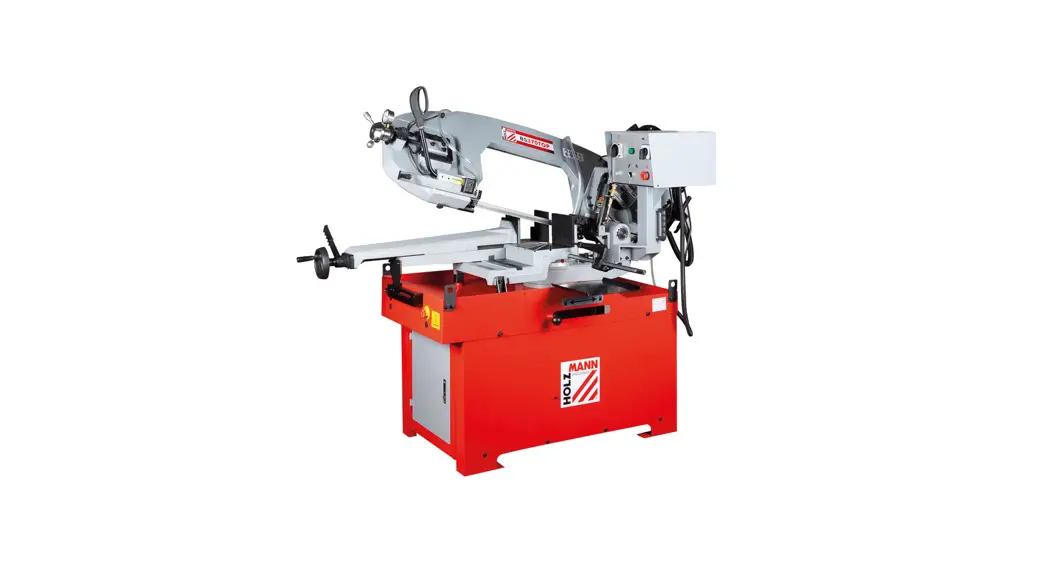
![]() BS320TOP Head Band Saw
BS320TOP Head Band Saw
User Manual
HOLZMANN MASCHINEN GmbH
+43 (0) 7289 71562-0 | FAX 7289 71562-4
[email protected] | www.holzmann-maschinen.at BS320TOP
SAFETY SIGNS
SAFETY SIGNS
DEFINITION OF SYMBOLS
 | CE-Conform! – This product complies with the EC-directives. |
| Follow the instructions! | |
| Switch off the machine before maintenance and breaks and pull out the mains plug. | |
| Warning of pointed (sharp) tool | |
 | Dangerous electrical voltage |
| Wear personal protective equipment! |
Missing or non-readable se curity stickers have to be replaced immediately
TECHNIC
BS320TOP
| # | Qty | # | Qty | |||
| 1 | machine | 1 | 7 | fixation material machine | 24 | |
| 2 | workpiece stop | 1 | 8 | machine stand parts | 4 | |
| 3 | Lift ring | 4 | 9 | shelf | 2 | |
| 4 | water recycle hose | 1 | 10 | fixation material machine stand | 114 | |
| 5 | water recycle hose clamp | 1 | 11 | manual | 1 | |
| 6 | (hex wrench 3,6,8,10mm) | 4 | ||||
| Machine with assembled saw band and coolant pump | ||||||
Components
BS320TOP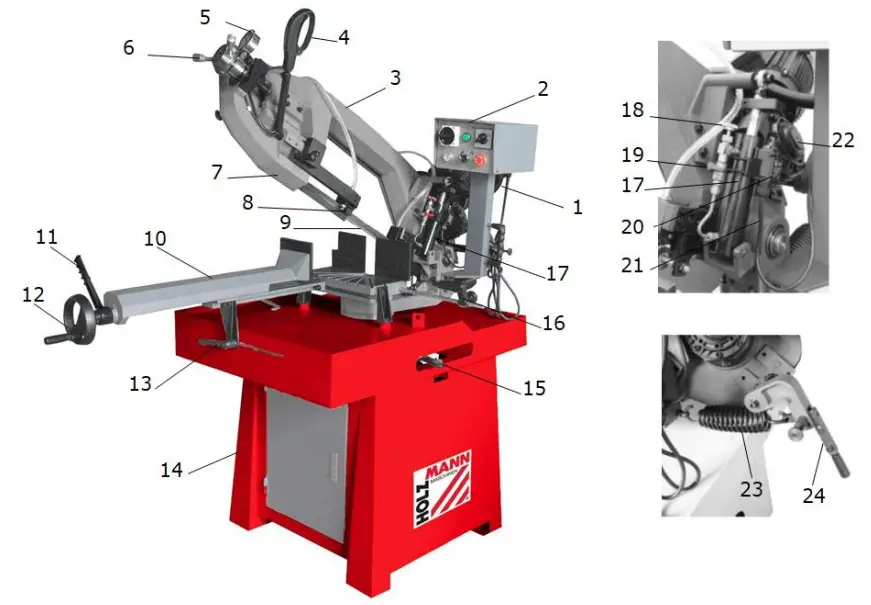
| 1 | motor | 13 | handle adjustable jaw, vise |
| 2 | switch box | 14 | machine stand |
| 3 | saw bow | 15 | saw arm lock lever |
| 4 | handgrip/trigger | 16 | workpiece stop |
| 5 | blade tension gauge | 17 | cylinder |
| 6 | saw bandtension adjustment wheel | 18 | feed rate adjustment knob |
| 7 | saw bandcover | 19 | ON/OFF valve at the hydraulic cylinder |
| 8 | saw band guidance / guard | 20 | automatic shutt off switch |
| 9 | saw band | 21 | shut-off valve cylinder |
| 10 | vice | 22 | gear box |
| 11 | quick lock lever for vice | 23 | saw arm return spring |
| 12 | handwheel vice | 24 | manueller Betrieb / handle, auto/manual operation |
Technical data
| BS320TOP | |
| voltage | 400 V / 3 / (50 Hz) |
| power drive-moter | 1,5 kW (2) / 1,1 kW (1) |
| power coolant pumpt | 45 W |
| saw band dimension | 2680 x 27 x 0,9 mm |
| Schnittgeschwindigkeit cutting speed | 70 / 35 m/min |
| fly-wheel diameter | 300 mm |
| swivel range | L: 0 – 45° R: 0 – 60° |
| cutting performance mm | 0°: 245 / 45°R: 190 / 60°R: 140 / 45°L: 190 |
| cutting performence mm | 0°: 245 / 45°R: 155 / 60°R: 125 / 45°L: 155 |
| cutting performance mm | 0°: 320 x 195 / 45°R: 180×140 60°R: 140×125 / 45°L: 200×140 |
| distance floor to vise support | 950 mm |
| recommended gear oil-type | SAE 80W-90 |
| amount of gear oil | 0.5 l |
| coolant tank volume | 15 l |
| Nettogewicht net weight | 320 kg |
| Bruttogewicht gross weight | 384 kg |
| Verpackungsmaße (L x B x H) packaging dimension (L x W x H) | 1600 x 805 x 955 mm |
| Maschinenmaße (L x B x H) machine dimension (L x W x H) | 2000x1500x1900 mm |
| Sound power level LWA | 88.3 dB(A) k=3dB(A) |
| Sound pressure level LPA | 75.7 dB(A) k= 3dB(A) |
Notice Noise indications: The figures given are emission levels and not necessarily safe working levels. Although there is a relationship between the level of noise emission and the level of noise exposure, it cannot be used reliably to determine whether further protective measures are necessary or not. Factors influencing the actual level of exposure of workers include the characteristics of the workspace, other sources of noise, etc., i.e. the number of machines and other nearby processes and the length of time an operator is exposed to noise. In addition, the permissible exposure level may vary from country to country. However, this information should allow the user of the machine to better assess the hazards and risks.
PREFACE
Dear Customer!
This operating manual contains information and important notes for safe start-up and handling of the head band BS320TOP hereinafter referred to as “machine”. The manual is an integral part of the machine and must not be removed. Keep it for later use in a suitable place, easily accessible to users (operators), protected from dust and moisture, and enclose it with the machine if the machine is passed on to third parties!
Please pay special attention to the chapter Safety!
Due to the constant further development of our products, illustrations and contents may differ slightly. If you notice any errors, please inform us.
Subject to technical changes!
Check the goods immediately after receipt and note any complaints on the consignment note when taking over the goods from the deliverer!
Transport damage must be reported separately to us within 24 hours.
HOLZMANN cannot accept any liability for unnoticed transport damage.
Copyright © 2020
This documentation is protected by copyright. All rights reserved! Especially the reprint, the translation and the extraction of photos and illustrations will be prosecuted.
The place of jurisdiction shall be the Regional Court of Linz or the court responsible for 4170 Haslach.
Customer Service Address
HOLZMANN MASCHINEN GmbH
4170 Haslach, Marktplatz 4
AUSTRIA
Tel +43 7289 71562 – 0
Fax +43 7289 71562 – 4
[email protected]
SAFETY
This section contains information and important notes on safe commissioning and handling of the machine.![]() For your own safety, read these operating instructions carefully before putting the machine into operation. This will enable you to handle the machine safely and prevent misunderstandings as well as personal injury and damage to property. In addition, observe the symbols and pictograms used on the machine as well as the safety and hazard information!
For your own safety, read these operating instructions carefully before putting the machine into operation. This will enable you to handle the machine safely and prevent misunderstandings as well as personal injury and damage to property. In addition, observe the symbols and pictograms used on the machine as well as the safety and hazard information!
13.1 Intended Use of the Machine
The machinery is intended exclusively for the following operations: For sawing/cutting through metals, castings and plastics, or other materials that are not hazardous to health or do not generate dust, within the specified technical limits.
HOLZMANN MASCHINEN assumes no responsibility or warranty for any other use or use beyond this and for any resulting damage to property or injury.
13.1.1 Technical Restrictions
The machine is intended for use under the following ambient conditions:
| Rel. Humidity: | max. 70 % |
| Temperature (Operation) | +5° C bis +40° C |
| Temperature (Storage, Transport) | -20° C bis +50° C |
13.1.2 Prohibited Applications / Hazardous Misapplications
- Operating the machine without adequate physical and mental aptitude
- Operating the machine without knowledge of the operating instructions
- Changes in the design of the machine
- Operating the machine in a potentially explosive environment (machine can generate ignition sparks during operation)
- Operating the machine outside the technical limits specified in this manual
- Remove the safety markings attached to the machine.
- Modify, circumvent or disable the safety devices of the machine.
- Processing of wood-based materials
- Machining of a workpiece which is not securely clamped in the vise.
The improper use or disregard of the versions and instructions described in this manual will result in the voiding of all warranty and compensation claims against Holzmann Maschinen GmbH.
13.2 User Requirements
The machine is designed for operation by one person. The physical and mental aptitude as well as knowledge and understanding of the operating instructions are prerequisites for operating the machine. Persons who, because of their physical, sensory or mental abilities or their inexperience or ignorance, are unable to operate the machinery safely must not use it without supervision or instruction from a responsible person.
Please note that local laws and regulations may determine the minimum age of the operator and restrict the use of this machine!
Put on your personal protective equipment before working on the machine.
Work on electrical components or equipment may only be carried out by a qualified electrician or under the instruction and supervision of a qualified electrician.
13.3 Safety Devices
The machine is equipped with the following safety devices:
| Protective cover saw band (back-side) | |
 | Micro switch saw arm/cylinder |
 | Micro switch saw band tension |
 | Adjustable saw band guide/guard |
13.4 General Safety Instructions
To avoid malfunctions, damage and health hazards when working with the machine, the following points must be observed in addition to the general rules for safe working:
- Before start-up, check the machine for completeness and function. Only use the machine if the guards and other non-parting guards required for machining have been fitted, are in good operating condition and have been properly maintained.
- Choose a level, vibration-free, non-slip surface for the installation location.
- Ensure sufficient space around the machine!
- Ensure sufficient lighting conditions at the workplace to avoid stroboscopic effects.
- Ensure a clean working environment.
- Only use perfect saw bands that are free of cracks and other defects (e.g. deformations).
- Remove tool keys and other adjustment tools before switching on the machine.
- Keep the area around the machine free of obstacles (e.g. dust, chips, cut parts, etc.).
- Check the strength of the machine connections before each use.
- Never leave the running machine unattended. Switch off the machine before leaving the working area and secure it against unintentional or unauthorised recommissioning.
- The machine may only be operated, serviced or repaired by persons who are familiar with it and who have been informed of the hazards arising from this work.
- Ensure that unauthorised persons maintain a safe distance from the machine and keep children away from the machine.
- When working on the machine, never wear loose jewellery, loose clothing, ties or long, open hair.
- Hide long hair under hair protection.
- Wear close-fitting protective clothing and suitable protective equipment (eye protection, dust mask, ear protection; gloves only when handling tools).
- Always work with care and the necessary caution and never use excessive force.
- Do not overload the machine!
- Shut down the machine and disconnect it from the power supply before carrying out any adjustment, conversion, cleaning, maintenance or repair work. Before starting any work on the machine, wait until all tools or machine parts have come to a complete standstill and secure the machine against unintentional restarting.
- Do not work on the machine if it is tired, not concentrated or under the influence of medication, alcohol or drugs!
- Do not use the machine in areas where vapours from paints, solvents or flammable liquids represent a potential danger (danger of fire or explosion!).
13.5 Electrical Safety
- Ensure that the unit is earthed.
- Only use suitable extension cords.
- Proper plugs and suitable sockets reduce the risk of electric shock!
- Use of the power tool in a humid environment is only permitted if the power source is protected by a residual current circuit breaker.
13.6 Special Safety Instructions for Band-Saws
- Risk of injury to hands/fingers from the saw band during operation.
- Risk of injury/cutting hazard due to unburred cutting edges.
- Risk of injury due to breakage or ejection of the saw band or parts thereof, especially in the event of overloading or incorrect running direction of the saw band.
- Hearing damage, unless the user has taken precautions for hearing protection.
- Risk of injury to the eye from flying parts, also with protective goggles.
13.7 Hazard Warnings
Despite their intended use, certain residual risks remain. Due to the design and construction of the machine, hazardous situations may occur when handling the machines, which are identified as follows in these operating instructions:
![]() DANGER
DANGER
A safety instruction designed in this way indicates an imminently hazardous situation which, if not avoided, will result in death or serious injury.
![]() WARNING
WARNING
Such a safety instruction indicates a potentially hazardous situation which, if not avoided, may result in serious injury or even death.
![]() CAUTION
CAUTION
A safety instruction designed in this way indicates a potentially hazardous situation which, if not avoided, may result in minor or moderate injury.
![]() NOTE
NOTE
A safety notice designed in this way indicates a potentially hazardous situation which, if not avoided, may result in property damage.
Irrespective of all safety regulations, your common sense and appropriate technical suitability/training are and will remain the most important safety factor for error-free operation of the machine. Safe working depends primarily on you!![]() WARNING
WARNING
Damaged or insufficiently strong hoists and load slings can result in serious injury or even death. Therefore, check hoists and load slings for sufficient load capacity and perfect condition before use. Attach the loads carefully. Never stand under suspended loads!
To ensure proper transport, also observe the instructions and information on the transport packaging regarding centre of gravity, attachment points, weight, means of transport to be used and the prescribed transport position, etc. 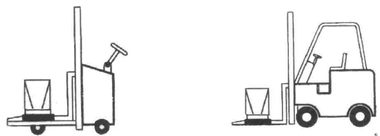
Before unpacking, transport the delivered product with a lift truck or stacker to the desired installation site.
If you transport the machine with a vehicle, make sure that the load is properly secured, and secure the wheels so that the machine remains fixed in position!
Lifting out of the packaging for assembly and positioning at the workplace: Only by means of suitable lifting equipment!
The machine is heavy. Load lifting slings are required to remove it from the packaging. They can be attached underneath the table to lift the machine from the transport pallet.
Note that any lifting equipment used (crane, forklift, sling, etc.) must be in perfect condition.
ASSEMBLY
15.1 Preparatory activities
15.1.1 Delivery content
Please check the product contents immediately after receipt for any eventual transport damage or missing parts. Claims from transport damage or missing parts must be placed immediately after initial machine receipt and unpacking before putting the machine into operation. Please understand that later claims cannot be accepted anymore.
15.1.2 Workplace requirements
The workplace has to fulfill the requirements.
The ground has to be even, in level and hard. It must be suitable at least to weight it with double weight per square meter than the machines net weight.
The chosen workplace must have access to a suitable electric supply net hat complies with the machines requirements.
You must also secure a distance of at least 0.8 m around the machine all around. In front of and behind the machine, the necessary distance for feeding long workpieces must be provided.
15.1.3 Cleaning the machine
Remove the corrosion protection agent that is applied to the parts without painting. This can be done with the usual solvents. Do not use nitro solvents or similar agents and under no circumstances use water.
15.2 Assembly
The machine comes pre-assembled, it is necessary to reassemble the components that have been disassembled for transport according to the following instructions.
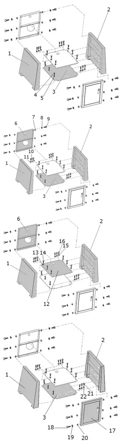 | 1. Machine stand assembly Connect the left (1) and right side parts, (2) with the base plate (3) using 6 screws M6x12 (4) and 6 nuts M6 (5). Mount the rear panel (6) to the left (1) and right side panel (2) using 6 nuts M8 (7), 6 washers 8 mm (8) and 6 screws M8x20 (9). Connect the rear panel (6) to the base plate (3) with 3 screws M6x12 (10) and 6 nuts M6 (11). Mount the shelf (12) to the left (1) and right side panels (2) using 6 M6x12 screws (14) and 6 M6 nuts (13). Connect the rear panel (6) to shelf (12) with 3 screws M6x12 (16) and 6 nuts M6 (15). Connect the front door (17) to the left (1) and right side panels (2) using 6 M8x20 screws (18), 6 8 mm washers (19) and 6 M8 nuts (20). Connect the front door (17) to the base plate (3) with 3 screws M6x12 (21) and 6 nuts M6 (22). |
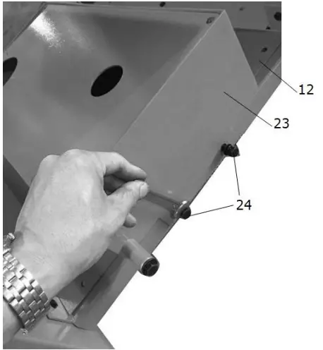 | 2. Coolant pump assembly Mount the coolant pump (23) to the bottom plate (12) with two screws M6x12 (24). |
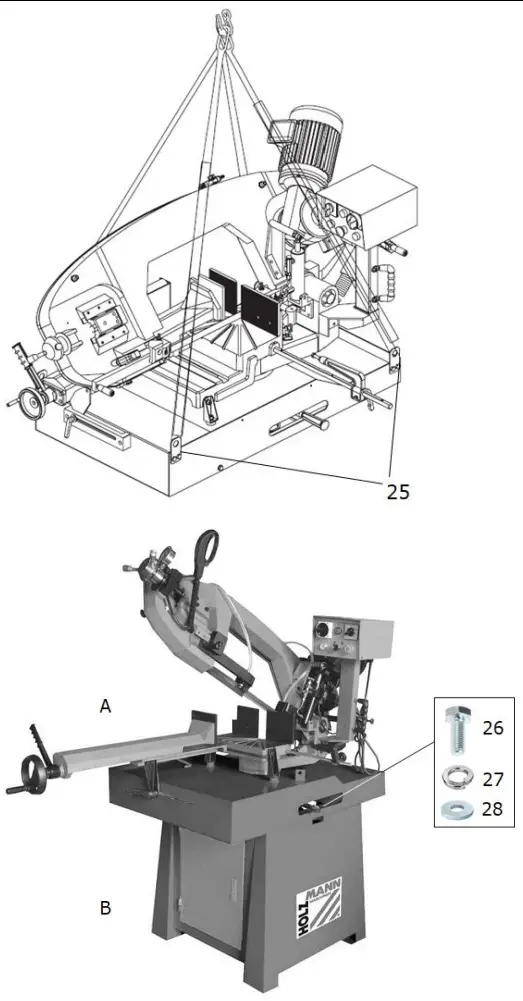
| 3.Saw head assembly The machine is heavy. Load lifting slings are required to remove it from the packaging. These slings are attached to the four lifting rings (25) in order to lift the machine and place it on the base frame.WARNING Damaged or insufficiently strong hoists and load slings can result in serious injury or even death. Therefore, check hoists and load slings for sufficient load capacity and perfect condition before use. Attach the loads carefully. Never stand under suspended loads! NOTICE: |
 | |
 | 4. Workpiece stop assembly Screw the thread (29) of the workpiece stop into the borehole on the vice (29). |
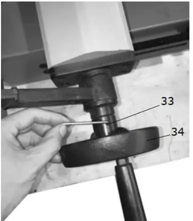 | 5. Handwheel for the vice assembly Mount the handwheel (34) and tighten the set screw (33) with a 3mm Allen key. |
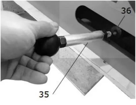 | 6.Saw arm lock lever assembly The handle (34) is screwed directly to the locking bar (35). |
 WARNING
Dangerous electrical voltage! Connection of the machine as well as electrical inspections, maintenance and repair may only be carried out by qualified personnel or under the supervision and supervision of a qualified electrician!
NOTICE![]() Heavy current machines must always be connected to 3 phases and an earthing.
Heavy current machines must always be connected to 3 phases and an earthing.
Check the correct running direction of the lathe immediately after making the electrical connection! If necessary, replace two of the three phases (L1/L2 or L1/L3)!
The machine is operated with high voltage current (400 V, 3~, 50 Hz). The use of 16 A fuses is recommended.
15.3.1 Establishing the power connection
To connect the machine to the electrical mains, proceed as follows:
- Check that the supply voltage and current frequency correspond to the specifications on the machine nameplate.
- Use a suitable device to check that the zero connection and earthing are working properly.
- The power supply circuit must be equipped with overvoltage protection (RCD with maximum residual current of 30 mA).
- For the required cross-section of the supply cables, please refer to the current carrying capacity table. (Make sure that the cables are in good condition and suitable for power transmission. Undersized cables reduce the power transmission and heat up considerably.)
- Connect the supply cables to the corresponding terminals in the input box (L1, L2, L3, N, РЕ) – see following figure. If there is a СЕЕ plug, the connection to the mains is made by an appropriately supplied СЕЕ coupling (L1, L2, L3, N, РЕ).
| Plug connection 400V: | 5-wire: with N conductor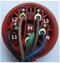 | 4-wire: without N conductor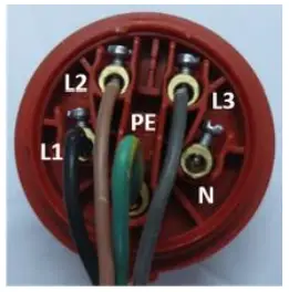 |
OPERATION
Device to be operated in a perfect state only. Inspect the device visually every time it is to be used. Check in particular the safety equipment, electrical controls, electric cables and screwed connection for damage and if tightened properly. Replace any damaged parts before operating the device.
16.1 Operation instructions![]() Carry out all setting and adjustment work only after disconnecting from the electrical mains!
Carry out all setting and adjustment work only after disconnecting from the electrical mains!
![]() NOTICE
NOTICE
Check the machine before starting work:
- Safety devices in place and in good condition
- Check saw band for wear and tear and replace if necessary
- Check coolant level and fill up if necessary
- Check moving parts for ease of movement
- Check all components for correct seating and functioning especially the screws of saw band guard and the lever.
- All tool for maintenance/servicing removed from machine.
- Place the saw band guard as close as possible to the workpiece Check before each cut:
- Cutting angle correctly adjusted?
- Vice fixed?
- Make sure that the material to be machined is properly fixed in the vice.
- Mare sure that coolant circulates properly.
- Saw band direction correct?
- Long workpieces must be support (eg stand, roll stand,…)
- Always run teh motor at full speed before you start cutting (wait at least 30sec after starting the saw band)
- Never start the machine with the saw band pressed down (10mm distance)
16.2 Operation
16.2.1 Operating console
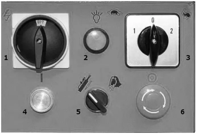 | Main switch (1) Switch power supply on and off Control lamp (2) Lights up when the power supply is switched on Selector switch for cutting speed (3) Select the speed of the saw band: NEUTRAL (switch position 0) START button (4) Switch on band saw in automatic mode Selector switch for operating mode (5) Selection of manual or automatic operation of the saw arm. EMERGENCY STOP switch (6) Switch off the machine in an emergency. Only after the malfunction has been rectified and there are no risks left: Release the EMERGENCY switch by turning it clockwise. The machine can now be started again. |
16.2.2 Automatic operation
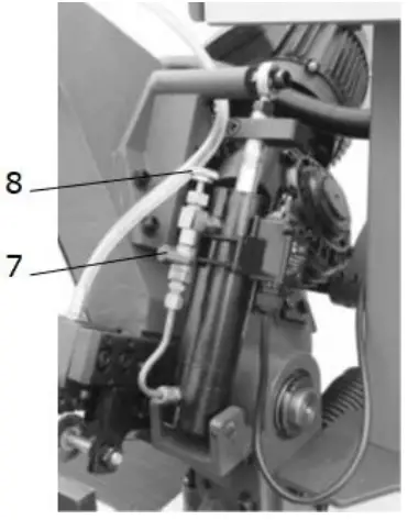 | Lift the saw arm to the maximum height to release the spring. Close the feed control valve (8) and the ON/OFF valve (7) to hold the arm in position. Lift the fixing knob (9). Now the lever (10) can be moved upwards to the “automatic” position. To fix the lever (10), return the fixing knob (9) to its original position. Turn the selector switch of the operating mode (11) counterclockwise to automatic operation (see 16.2.1). Select the cutting speed (12). Turn the main switch (13) to the ON position. Control lamp (14) must light up. Clamp workpiece in the vice. Switch the START (15) button. |
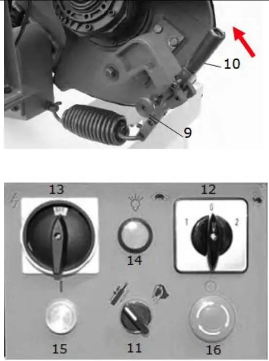 | Make sure that the saw band runs in the right direction. Open the ON/OFF valve (7) by turning it counterclockwise. NOTICE: slightly press the saw arm down to allow air bubbles to escape from the hydraulic cylinder. Slowly open the feed control valve (8) counter-clockwise until the saw arm descends and allow the saw to cut at an appropriate feed rate. When the cut is complete (lower position reached), the machine switches off automatically by the limit switch. NOTICE: if the saw arm falls too fast, close the ON/OFF valve (7) fully to stop its descent. NOTICE: a saw arm that falls too fast can cause the saw band to stop on the workpiece and the machine to switch off automatically. In an emergency you can stop all machine functions immediately by pressing the EMERGENCY STOP switch (16). |
16.2.3 Manual operation
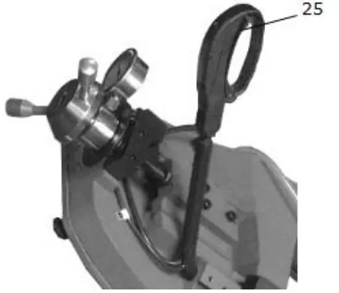
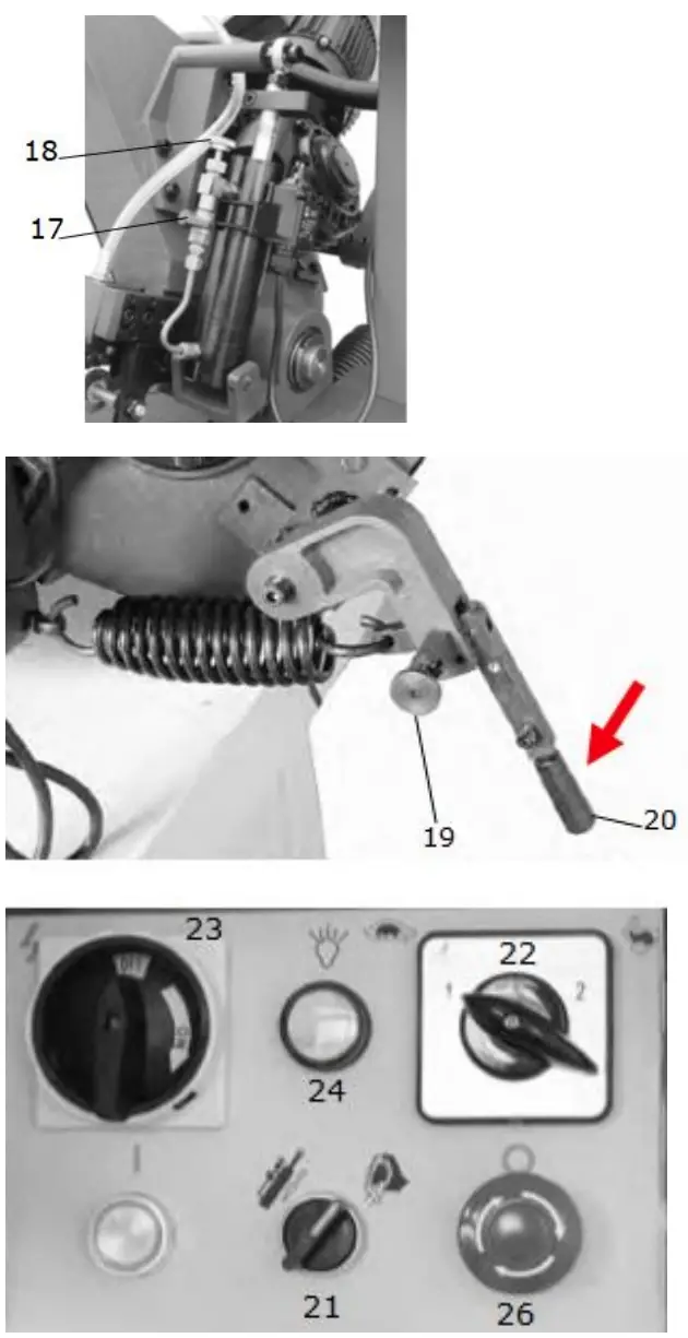 | Close the ON/OFF valve (17). Lift the saw arm to the maximum height Lift the fixing knob (19). Now the lever (20) can be moved downwards to the “manual” position. Return the fixing knob (19) to its original position. Turn the selector switch of the operating mode (21) clockwise to manual operation (see 16.2.1). Select the cutting speed (22). Turn the main switch (23) to the ON position. Control lamp (24) must light up. Clamp workpiece in the vice. Fully open the feed control valve (18) by turning the valve clockwise. Fully open the ON/OFF valve (17) by turning it clockwise. Hold the saw arm at the handgrip. Press the trigger switch (25) on the handgrip to start the machine. Saw band is running at the selected speed. Check that the saw band runs in the right direction. Slowly move the saw arm down and cut the workpiece. |
 | In an emergency you can stop all machine functions immediately by pressing the EMERGENCY STOP switch (26). |
16.3 Settings
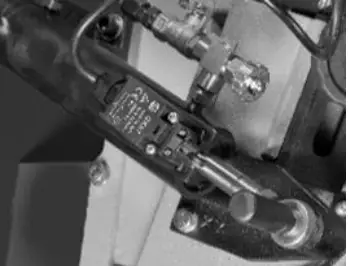
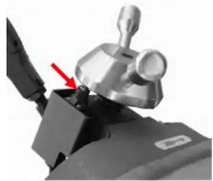
16.3.1 Saw band tension
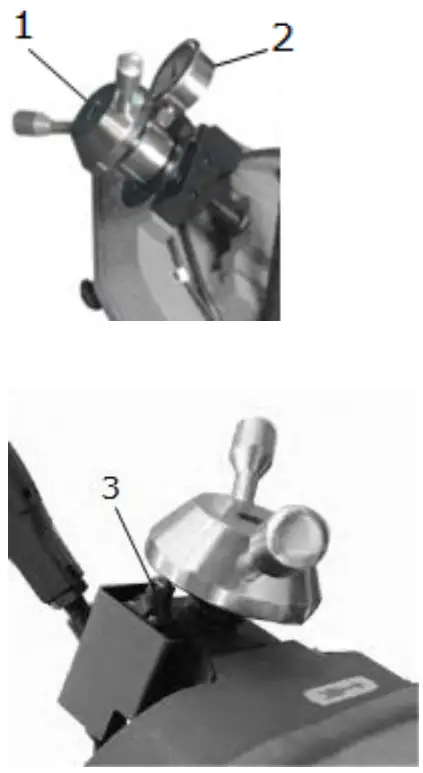 | Correct saw band tension is essential for a long life of the saw band and to ensure the quality of the cut. For this purpose the saw band tension must be adjusted with the hand wheel (1). The correct saw band tension is achieved when the handwheel is turned until it touches the microswitch (3). Only at this point can the machine be put into operation. The current belt tension is displayed on the blade tension gauge (2). NOTICE: The position of this microswitch is factory set. For this reason, when replacing the saw band, it is necessary to use only saw bands that comply with the technical data (see 4.3). |
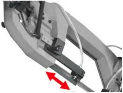
16.3.1 Saw band guide
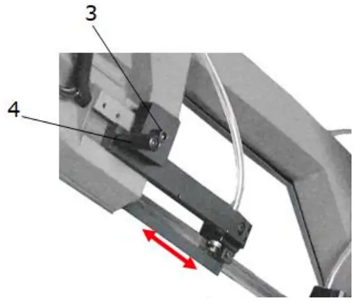 | The saw band guide should be close to the workpiece. This helps to ensure a clean cut. The following steps are necessary: Loosen the screw (3) with an allen key. Push the saw band guide with the handle (4) into the desired position. Retighten the screw (3) with the allen key. |
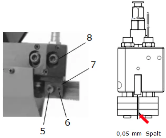 | Adjustment The saw band guide (7) is preset for a saw band with a thickness of 0.9 mm. However, if the saw band guide needs to be adjusted, the following setting should be carried out: The lateral bearings of the saw band guide (7) can be adjusted by loosening the screw (5) and the adjusting screw (6). Adjust the bearings so that the saw band can slide smoothly and there is a gap of approx. 0.05mm between the bearings and the saw band. Retighten the screw (5). Loosen the screws (8) and adjust the upper saw band guide (7). Check that there is at least 0.2-0.3 mm space between the saw band and the upper bearing. |
16.3.2 Adjusting the saw band tracking
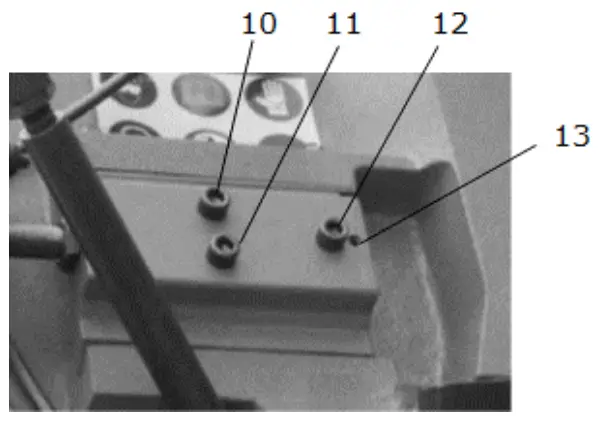 | The saw band tracking has been adjusted in the factory. However, if adjustment is necessary because the saw band does not run centrally on the saw band wheel, the following steps must be carried out: Move the saw arm to its uppermost position, fix it and close the hydraulic control. Remove the rear protective cover of the saw arm. To do this, loosen and remove all screws. Loosen the hexagon head screws (10,11,12) (only loosen, do not remove). Use the adjusting screw (13) to adjust the inclination of the wheel and thus the saw band track. o Tightening the screw (13) moves the saw band to the shoulder side of the wheel, o Loosening moves the belt away. and then re-tighten the hexagon head screw (13). Tighten the hexagon head screws in the following chronological order (12,11,10). Re-install the protective cover of the saw arm. Finally the tracking must be checked, if it is not yet correct repeat the above steps |
16.4 Adjusting the vice
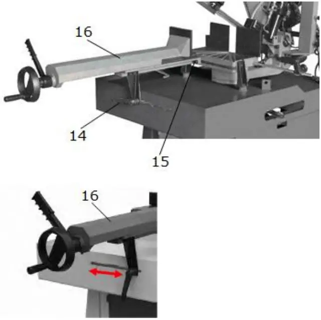 | Loosen the adjustable vice jaw by turning the lever (14) counter-clockwise. Release the vice (16) by loosening the 2 allen screws (15). The vice (16) can now be placed in the desired position. Retighten the 2 allen screws (15). Fix the vice jaw by turning the lever (14) clockwise. |
16.4.1 Clamping the workpiece
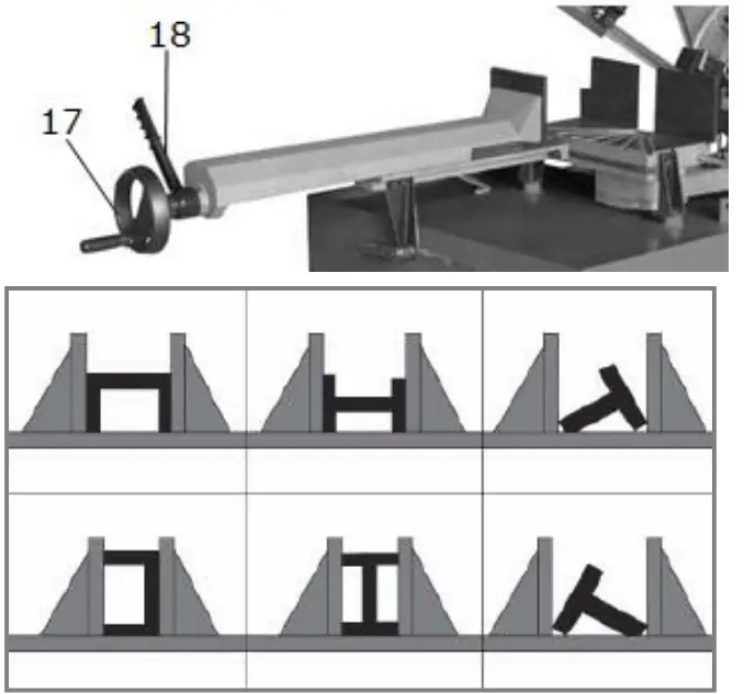 | Open the vice with the hand wheel (17) Insert workpiece so that it rests against the fixed jaw. Insert workpiece correctly (see figure on the right) Protruding workpieces must be supported! Move the movable jaws to the workpiece by turning the hand wheel (17) and leave a gap of approx. 3-4 mm. Clamp the workpiece with the quick lock lever (18). o This facilitates rapid re-clamping of workpieces of the same length. |
16.5 Adjusting the cutting angle
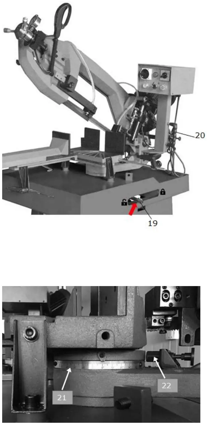 | The cutting angle between vice and saw band can be adjusted within the specified angle range (see technical Data). The saw arm can be swivelled to the right at an angle of up to 60°. This requires a positioning of the vice to the left. Procedure: see 16.4 If the saw arm is positioned on the left side, it is possible to cut at an angle of up to 45°. This requires a positioning of the vice to the right. Procedure: see 16.4 NOTICE: Take into account the lower cutting performance for angle cutting (see technical data)! Swivelling the saw arm Procedure: Turn the saw arm lock lever (19) to the left. Saw arm can be swivelled. Use the handle (20) to turn the saw arm until you reach the mechanical stop. Check if the desired angle corresponds to the indication on the scale (21). Use the locking screw (22) to arrest the set angle. Turn the saw arm lock lever (19) to the right. |
CLEANING, MAINTENANCE, STORAGE, DISPOSAL
17.1 Cleaning![]() NOTICE
NOTICE
Wrong cleaning agents can attack the varnish of the machine. Do not use solvents, nitro thinners, or other cleaning agents that could damage the machine’s paint.
Observe the information and instructions of the cleaning agent manufacturer!
Prepare the surfaces and lubricate the bare machine parts with an acid-free lubricating oil.
Regular cleaning is a prerequisite for the safe operation of the machine and its long service life.
Therefore, clean the device after each use of chips and dirt particles.
17.2 Maintenance![]() WARNING
WARNING
Danger due to electrical voltage! Handling the machine with the power supply up may result in serious injury or death. Always disconnect the machine from the power supply before servicing or maintenance work and secure it against unintentional restart!
The machine is low-maintenance and only a few parts have to be serviced. Nevertheless, any faults or defects which may affect the safety of the user must be rectified immediately!
- Before each start-up, make sure that the safety devices are in perfect condition and function properly.
- Check all connections for tightness at least once a week.
- Regularly check that the warning and safety labels on the machine are in perfect and legible condition.
- Use only proper and suitable tools.
- Only use original spare parts recommended by the manufacturer.
17.3 Inspection and Maintenance Plan
The type and degree of machine wear depends to a large extent on the operating conditions. The following intervals apply when the machine is used within the specified limits:
| Interval | component | Action |
| After work | Machine | Clean the machine from chips Lubricate plank metal surfaces with a thin layer of oil Lubricate the sliding surfaces of the vice and the saw band guide with light machine oil |
| Coolant | Clean the lubricating coolant drain hole Check the coolant level and eventually fill up | |
| Saw band | Check the blade of wear | |
| Lift the saw arm upwards and release the tension of the saw band | ||
| Savety devices Emergency stop switch | Check for proper function | |
| Weekly | Machine | Clean the machine, especially the lubricant fluid tank |
| Coolant pump | Clean the suction filter and suction zone | |
| Saw band guide | Use compressed air to clean the saw band guide, the bearings and the drain hole of the lubrication cooling system. | |
| Saw band cover Flywheels | Clean the saw band cover and wheels | |
| Moving parts | Lubricate with a thin layer of lubricating oil or grease | |
| Monthly | Flywheels | Check the tightening of the flywheels screws |
| Saw band guide | Check the condition of the screws | |
| Motor fixture Protective device | Check the fastening screws of the motor, the pump and the protective devices for tightness. | |
| Half-yearly | Equipotential protection circuit | Continuity test |
17.4 Saw band replacement
- Lift the saw arm.
- Loosen the band tension with the hand-wheel.
- Slide the mobile band guide to far away as possible.
- Remove the band guard lock knob, remove the blade guard.
- Remove the old band, from the flywheel and the blade guide block.
- Assemble a new band by placing it first between the pads and then on the race of flywheels, paying
- Particular attention to the cutting direction of the teeth.
- Tension the band and make sure it perfectly fits inside the seat of the flywheels.
- Assemble the band guard, and fasten it with relative knobs.
- Check the safety microswitch is activated otherwise when electric connection will be restored the machine will not start.
- Always assemble bands having dimensions specified in this manual and for which the band guide heads have been set.
17.5 Checking the gear oil level![]()
![]() NOTICE
NOTICE
Waste oils are toxic and must not be allowed to enter the environment! If necessary, contact the local authorities for information on proper disposal.
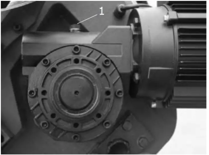 | The following steps are necessary to check the oil level: Bring the saw arm to its uppermost position, fix it and close the hydraulic control. Wait a few minutes until the oil has deposited. Loosen the vent screw (1) on the top of the gearbox. If the oil level is low, top up the recommended oil to the upper edge (amount and recommended oil-type please refer to technical data). |
STORAGE
![]() NOTICE
NOTICE
Improper storage can damage and destroy important components. Only store packed or unpacked parts under the intended environmental conditions!
When not in use, store the machine in a dry, frost-proof and lockable place to prevent the formation of rust on the one hand and to ensure that unauthorised persons and in particular children have no access to the machine on the other.
DISPOSAL
![]() Observe the national waste disposal regulations. Never dispose of the machine, machine components or equipment in residual waste. If necessary, contact your local authorities for information on the disposal options available.
Observe the national waste disposal regulations. Never dispose of the machine, machine components or equipment in residual waste. If necessary, contact your local authorities for information on the disposal options available.
If you buy a new machine or an equivalent device from your specialist dealer, he is obliged in certain countries to dispose of your old machine properly.
TROUBLE SHOOTING
![]() WARNING
WARNING
Danger due to electrical voltage! Manipulating the machine with the power supply up may result in serious injury or death. Before carrying out any troubleshooting work, always disconnect the machine from the power supply and secure it against unintentional recommissioning.
Many possible sources of error can be excluded in advance if the machine is properly connected to the mains.
If you are unable to carry out necessary repairs properly and/or do not have the required training, always consult a specialist to solve the problem.
| Fault | Possible cause | Remedy |
| Machine does not start | Machine not connected to power supply Fuse of power circuit defect or not suitable Cable defect | Check all power connections Change fuse Change cable |
| Saw band does not come to full speed, no power | To long extension cord Power supply not matching with motor requirements. Weak, instable/volatile power supply | change to suitable extension cord with sufficient cross-section, insulation and length Let check by electrician Contact electric power company |
| Motor gets hot very fast and has weak performance | Motor does not receive power on one or even 2 phases | Shut off machine immediately. Let the connection to supply circuit be checked by an electrician! |
| Saw band runs in opposite direction | 2 of the 3 leading phases are switched whether in Plug or socket | Shut off machine immediately. Let the connection to supply circuit be corrected by an electrician! |
| Machine vibrates | Placed on uneven underground Motor or any other parts loose | Modify check all screw joints if tightened |
| Bad cuts | too high descent velocity unsuitable saw band for cutted material worn saw band saw band not tensioned correctlysaw band guide outbalanced | Reduce the descent velocity Use e.g. for stainless steel HQ Bi-Metal bands only replace tension saw band correctly readjust saw band guide |
SCHALTPLAN / WIRING DIAGRAM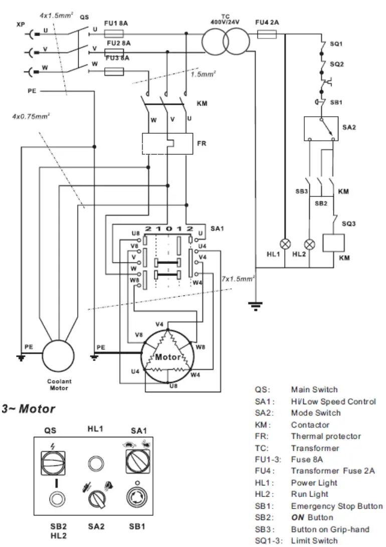
SPARE PARTS
![]() NOTICE
NOTICE
The installation of parts other than original spare parts leads to the loss of the guarantee! Therefore: When replacing components/parts, only use spare parts recommended by the manufacturer.
When you place a spare parts order please use the service formula you can find in the last chapter of this manual. Always take a note of the machine type, spare parts number and part name. We recommend to copy the spare parts diagram and mark the spare part you need.
Or use the electronic ordering opportunity via the spare parts catalogue or spare parts request form on our homepage You find the order address in the preface of this operation manual.
For electronic spare-parts catalogue please refer to our homepage (spare-parts)
exploded view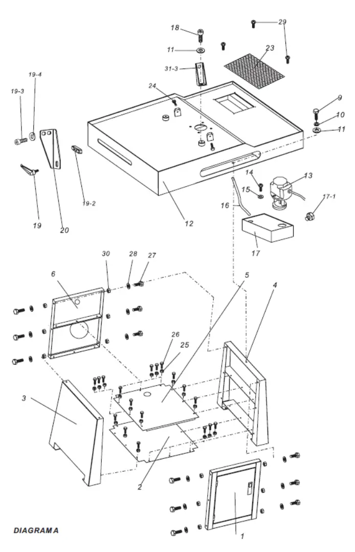
SPARE PARTS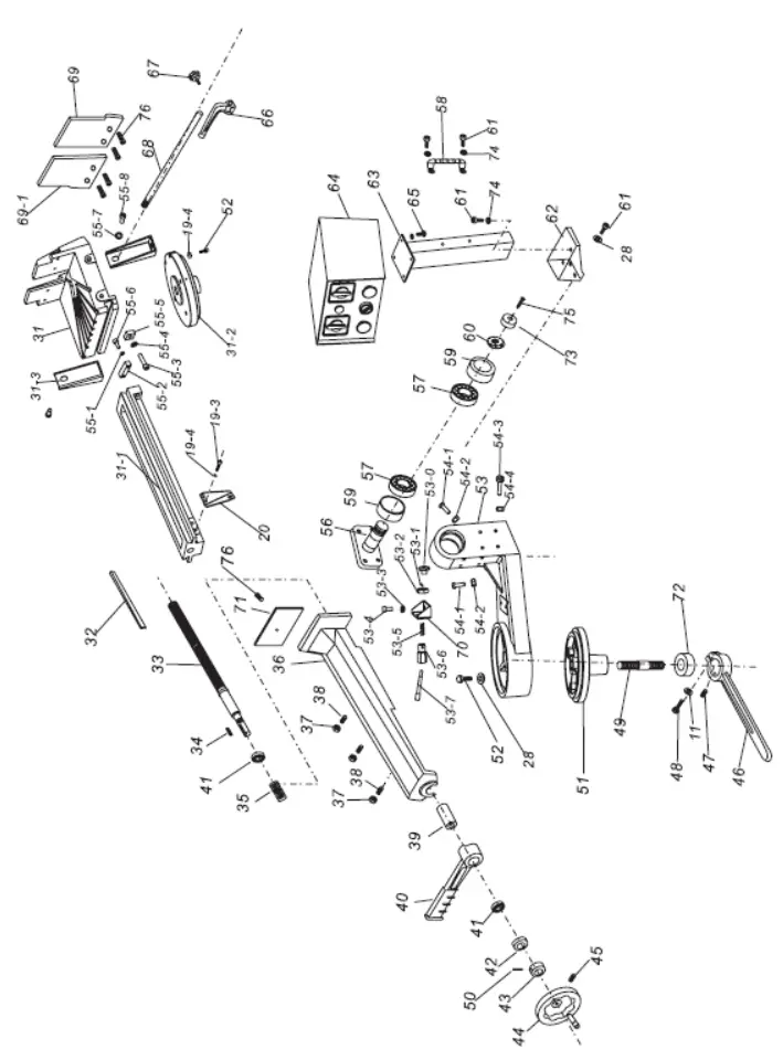
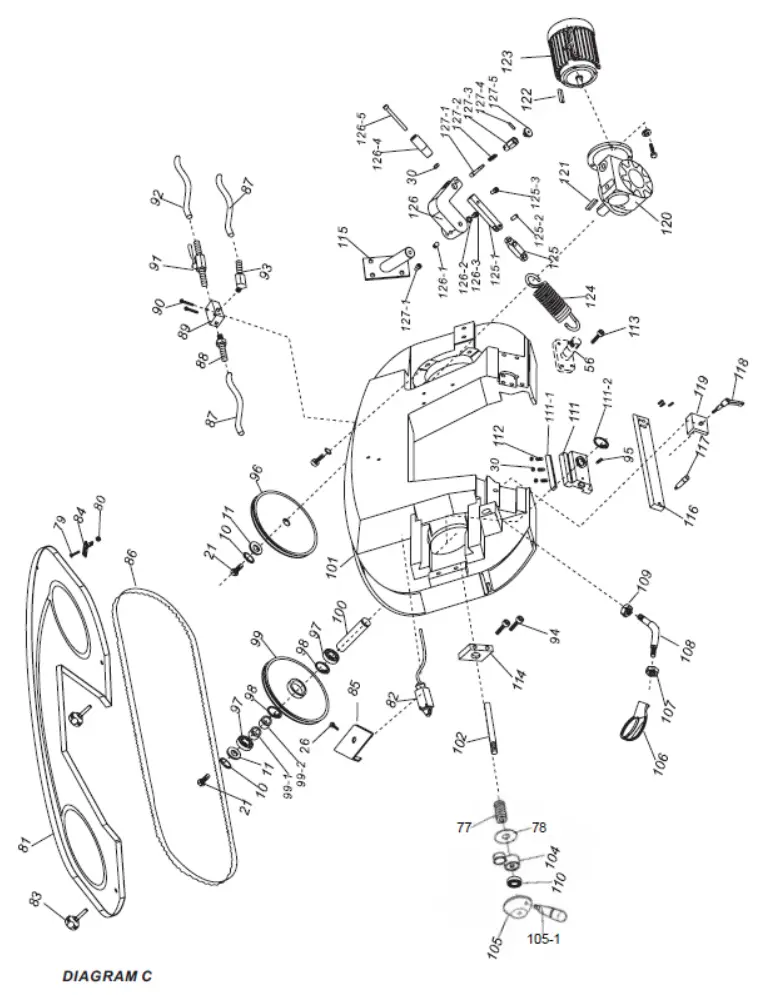
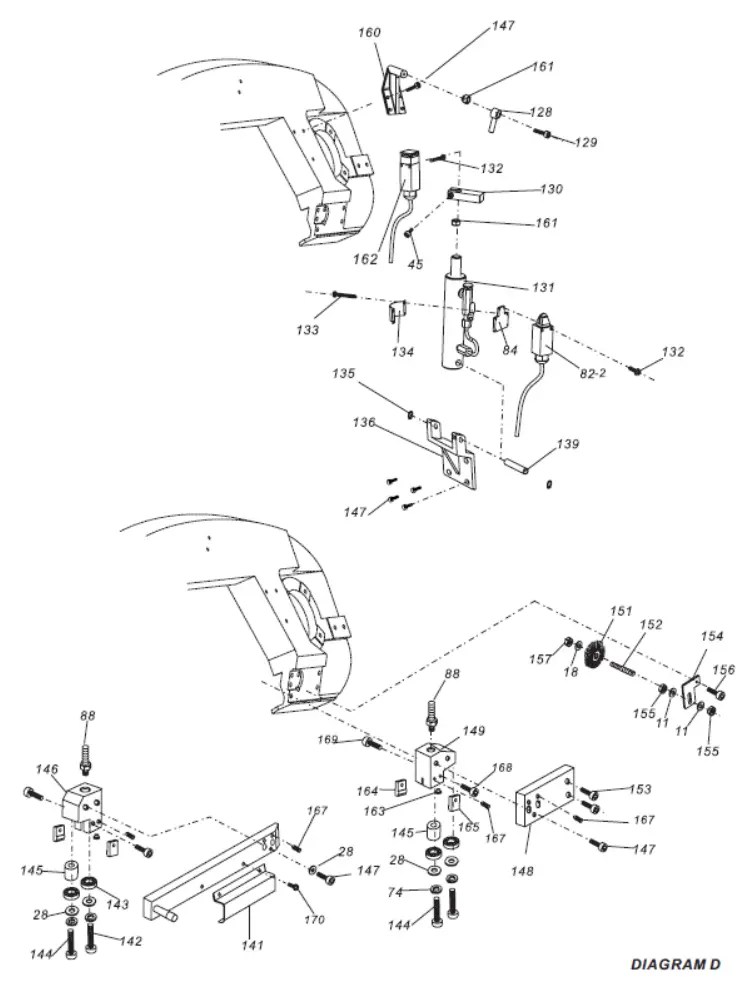
| No. | Description | No. | Description |
| 1 | Front panel w/door | 51 | Vise amount base |
| 2 | Bottom shelf | 52 | Allen screw M8x30 |
| 3 | Left side panel | 53 | Vise rotate base |
| 4 | Right side panel | 53-1 | Roll pin 2.5×22 |
| 5 | Upper shelf | 53-2 | Thin nut M16x1.5 |
| 6 | Rear panel | 53-3 | Washer 8mm |
| 9 | 9 Hex screw M10x25 | 53-4 | Allen screw M8x16 |
| 10 | Spring washer 10mm | 53-5 | Spring |
| 11 | 11 Washer 10mm | 53-6 | Hex tube |
| 12 | Base | 53-7 | Spindle rod |
| 13 | Coolant pump | 53-0 | Knurled Lever |
| 14 | Pan head screw M6x15 | 54-1 | Allen screw M10x20 |
| 15 | Washer 5mm | 54-2 | Hex nut M10 |
| 16 | Coolant hose | 54-3 | Spring lower holder |
| 17 | Coolant container | 54-4 | Hex nut M12 |
| 17-1 | 17-1 Container plug M12x10 | 55-1 | Spring washer 6mm |
| 18 | Hex head screw M10x16 | 55-2 | Slide guide |
| 19 | Ratchet lever | 55-3 | Allen screw M10x40 |
| 19-2 | Bolt guide | 55-4 | Spring washer M10 |
| 19-3 | Allen screw M8x16 | 55-5 | Screw guide M10 |
| 19-4 | Spring washer 8mm | 55-6 | Allen screw M6x20 |
| 20 | 20 Vice support | 55-7 | Washer 8mm |
| 23 | Filter | 55-8 | Allen screw M8x16 |
| 24 | Hex head screw M12x60 | 56 | Rotate shaft, saw bow |
| 25 | Hex nut M6 | 57 | Bearing 32006 |
| 26 | Hex head screw M6x12 | 58 | “U” handle |
| 27 | Hex head screw M8x20 | 59 | Bearing seat |
| 28 | Washer 8mm | 60 | Round nut M30 |
| 29 | Pan head screw M6x10 | 61 | Allen screw M8x20 |
| 30 | Hex nut M8 | 62 | Bracket, control box |
| 31 | Fixed jaw, vise | 63 | Support, control box |
| 31-1 | Segment, fixed jaw | 64 | Control box |
| 31-2 | Swing disc | 65 | Allen screw M6x12 |
| 31-3 | Support, vice | 66 | Stop, workpiece |
| 32 | Slide plate | 67 | Star type screw |
| 33 | Pivot shaft | 68 | Bar-stop |
| 34 | Key | 69 | Fixed jaw plate |
| 35 | Spring | 69-1 | 69-1 Fixed jaw plate |
| 36 | Adjustable jaw, vise | 70 | Bracket |
| 37 | Thin nut M8 | 71 | Adjustable jaw plate |
| 38 | Set screw M8x25 | 72 | Collar |
| 39 | Spacer | 73 | Cap, bearing |
| 40 | Quick lock lever | 74 | Spring washer 8mm |
| 41 | Bearing AXK2035 | 75 | Sunk head screw M8x16 |
| 42 | Cover, bearing | 76 | Allen screw M10x20 |
| 43 | Collar | 77 | Butterfly gasket |
| 44 | Vise handwheel | 78 | Plate |
| 45 | Set screw M6x10 | 79 | Panhead screw M4x10 |
| 46 | Saw arm lock lever | 80 | Hex nut M4 |
| 47 | Set screw M10x12 | 81 | Blade guard |
| 48 | Allen screw M10x35 | 82 | Micro-switch |
| 49 | Lock thread | 82-2 | Micro-switch |
| 50 | Roll pin | 83 | Guard lock(star-type screw) |
| No. | Description | No. | Description |
| 84 | Key, micro- switch | 126-4 | Allen screw M10x25 |
| 85 | Guard, micro- switch | 126-5 | Allen screw M8x80 |
| 86 | Blade | 127-1 | Rod M10x30 |
| 87 | Hose, coolant water | 127-2 | Spring |
| 88 | Hose fitting | 127-3 | Hex tube |
| 89 | 3-way fitting | 128 | 128 Jointer |
| 90 | Pan head screw M5x30 | 129 | 129 Allen screw M10X40 |
| 91 | Valve | 130 | 130 Limited block |
| 92 | Supply hose | 131 | 131 Hydraulic cylinder |
| 93 | Hose fitting | 132 | 132 Pan head screw M4x25 |
| 94 | Allen screw M10x55 | 133 | 133 Pan head screw M4x40 |
| 95 | Set screw M8x12 | 134 | 134 Support, micro switch |
| 96 | Drive wheel | 135 | 135 Circle ring 12mm |
| 97 | Bearing 6007 | 136 | 136 Lower support, hydraulic cylinder |
| 98 | Circle ring 55mm | 139 | 139 Roll pin |
| 99 | Idler wheel | 141 | 141 Blade safety guard |
| 99-1 | Spacer 1 | 142 | 142 Hex head screw M8x25 |
| 99-2 | Spacer 2 | 143 | 143 Bearing 608-2Z |
| 100 | Shaft, idler wheel | 144 | 144 Hex head screw M8x35 |
| 101 | Saw bow | 145 | 145 Spacer, guide |
| 102 | Tension bar | 146 | 146 Guide, mobile |
| 104 | Blade tension gauge | 147 | 147 Allen screw M8x25 |
| 105 | Tension adjust hand- wheel | 148 | 148 Bracket, fixed guide |
| 105-1 | Handle | 149 | 149 Fixed blade guide |
| 106 | Handgrip | 151 | 151 Chip brush |
| 107 | Hex nut M16 | 152 | 152 Brush rod |
| 108 | Rod-handgrip | 153 | 153 Allen screw M10x20 |
| 109 | Thin nut M20x2 | 154 | 154 Brush support |
| 110 | Thrust bearing | 155 | 155 Thin hex nut M10 |
| 111 | Slide, idler wheel | 156 | 156 Allen screw M10x16 |
| 111-1 | Adjusting wedge | 157 | 157 Hex nut M6 |
| 111-2 | Circle ring 30mm | 160 | 160 Upper support, Hydraulic cylinder |
| 112 | Set screw M8x25 | 161 | 161 Hex nut M10 |
| 113 | Allen screw M10x30 | 162 | 162 Micro switch (Limit switch) |
| 114 | Bracket, handle | 163 | 163 Upper teeth |
| 115 | Holder, arm stroke spring | 164 | 164 Fixed teeth |
| 116 | Bar, adjustable guard | 165 | 165 Adjustable teeth |
| 117 | Handle, bar | 167 | 167 Set screw M6x12 |
| 118 | Lock lever | 168 | 168 Allen screw M6x20 |
| 119 | Lock plate | 169 | 169 Allen screw M6x10 |
| 120 | Gear box | 170 | 170 Pan head screw M4x10 |
| 121 | Flat key, gear box | ||
| 122 | Flat key, motor | ||
| 123 | Motor | ||
| 124 | Spring, saw bow | ||
| 125 | Spring rod | ||
| 125-1 | Spring rod | ||
| 125-2 | Roll pin 8×18 | ||
| 125-3 | Allen screw M8x12 | ||
| 126 | Connector | ||
| 126-1 | Set screw M10x16 | ||
| 126-2 | Spring washer 10mm | ||
| 126-3 | Allen screw M10x25 |
CERTIFICATE OF CONFORMITY
Distributor
HOLZMANN MASCHINEN® GmbH
4170 Haslach, Marktplatz 4, AUSTRIA
Tel.: +43/7289/71562-0; Fax.: +43/7289/71562-4
www.holzmann-maschinen.at
name…………………………………………………………………….
HEAD BAND SAW………………………………………..
model…………………………………………………………
BS320TOP……………………………………………………….
EC-directives………………………………………..
2006/42/EC
2014/30/EC
applicable Standards………………………………….
EN ISO 16093:2017
EN 60204-1:2018
EN 55014-1:2017; EN 55014-2:2015
EN IEC 61000-3-2:2019; EN 61000-3-3:2013
Hereby we declare that the above mentioned machines meet the essential safety and health requirements of the above stated EC directives. Any manipulation or change of the machine not being explicitly authorized by us in advance renders this document null and void.
Technische Dokumentation
HOLZMANN-MASCHINEN GmbH
4170 Haslach, Marktplatz 4![]() Haslach, 30.06.2020
Haslach, 30.06.2020
Ort / Datum place/date
GUARANTEE TERMS
1.) Warranty:
For mechanical and electrical components Company Holzmann Maschinen GmbH garants a warranty period of 2 years for DIY use and a warranty period of 1 year for professional/industrial use – starting with the purchase of the final consumer (invoice date).
In case of defects during this period which are not excluded by paragraph 3, Holzmann will repair or replace the machine at its own discretion.
2.) Report:
In order to check the legitimacy of warranty claims, the final consumer must contact his dealer. The dealer has to report in written form the occurred defect to Holzmann. If the warranty claim is legitimate, Holzmann will pick up the defective machine from the dealer. Returned shippings by dealers which have not been coordinated with Holzmann will not be accepted. A RMA number is an absolute must-have for us – we won‘t accept returned goods without an RMA number!
3.) Regulations:
a) Warranty claims will only be accepted when a copy of the original invoice or cash voucher from the trading partner of Holzmann is enclosed to the machine. The warranty claim expires if the accessories belonging to the machine are missing.
b) The warranty does not include free checking, maintenance, inspection or service works on the machine. Defects due to incorrect usage through the final consumer or his dealer will not be accepted as warranty claims either.
c) Excluded are defects on wearing parts such as carbon brushes, fangers, knives, rollers, cutting plates, cutting devices, guides, couplings, seals, impellers, blades, hydraulic oils, oil filters, sliding jaws, switches, belts, etc.
d) Also excluded are damages on the machine caused by incorrect or inappropriate usage, if it was used for a purpose which the machine is not supposed to, ignoring the user manual, force majeure, repairs or technical manipulations by not authorized workshops or by the customer himself, usage of non-original Holzmann spare parts or accessories.
e) After inspection by our qualified staff, resulted costs (like freight charges) and expenses for not legitimated warranty claims will be charged to the final customer or dealer.
f) In case of defective machines outside the warranty period, we will only repair after advance payment or dealer’s invoice according to the cost estimate (incl. freight costs) of Holzmann.
g) Warranty claims can only be granted for customers of an authorized Holzmann dealer who directly purchased the machine from Holzmann. These claims are not transferable in case of multiple sales of the machine.
4.) Claims for compensation and other liabilities:
The liability of company Holzmann is limited to the value of goods in all cases.
Claims for compensation because of poor performance, lacks, damages or loss of earnings due to defects during the warranty period will not be accepted.
Holzmann insists on its right to subsequent improvement of the machine.
SERVICE
After Guarantee and warranty expiration specialist repair shops can perform maintenance and repair jobs. But we are still at your service as well with spare parts and/or product service. Place your spare part / repair service cost inquiry by filing the SERVICE form on the following page and send it: via Mail to [email protected]
or use the online complaint.- or spare parts order formula provided on our homepage www.holzmann-maschinen.at under the category service/news.
PRODUCT MONITORING
We monitor our products even after delivery.
In order to be able to guarantee a continuous improvement process, we are dependent on you and your impressions when handling our products. Let us know about:
– Problems that occur when using the product
– Malfunctions that occur in certain operating situations
– Experiences that may be important for other users
Please note down such observations and send them to us by e-mail, fax or letter post.
My experiences:
Name :
Product :
Purchasedate :
purchasedfrom :
e-mail :
Thank you for your cooperation !
CONTACT:
HOLZMANN MASCHINEN GmbH
4170 Haslach, Marktplatz 4 AUSTRIA
Tel : +43 7289 71562 0
Fax: +43 7289 71562 4
[email protected]
SERVICE FORM
Please tick one box from below:
service inquiry
Spare part inquiry
guarantee claim
senders information (* required)
first name, family name
street, house number
ZIP code, place
country
(mobile) phone
International numbers with country code
* E-Mail
Fax a
tool information
*Maschinentype/machine type:
required spare parts
| Part No° | description | number |
Problem description
Please describe amongst others in the problem:
What has cause the problem/defect, what was the last activity before you noticed the problem/defect?
For electrical problems: Have you had checked you electric supply and the machine already by a certified electrician?
Additional information
INCOMPLETELY FILLED SERVICE FORMS CANNOT BE PROCESSED!
FOR GUARANTEE CLAIMS PLEASE ADD A COPY OF YOUR ORIGINAL SALES / DELIVERY RECEIPT OTHERWISE IT CANNOT BE ACCEPTED.
FOR SPARE PART ORDERS PLEASE ADD TO THIS SERVICE FORM A COPY OF THE RESPECTIVE EXPLODED DRAWING WITH THE REQUIRED SPARE PARTS BEING MARKED CLEARLY AND UNMISTAKABLE.
THIS HELPS US TO IDENTIFY THE REQUIRED SPARE PARTS FASTLY AND ACCEL- LERATES THE HANDLING OF YOUR INQUIRY.
THANK YOU FOR YOUR COOPERATION!


