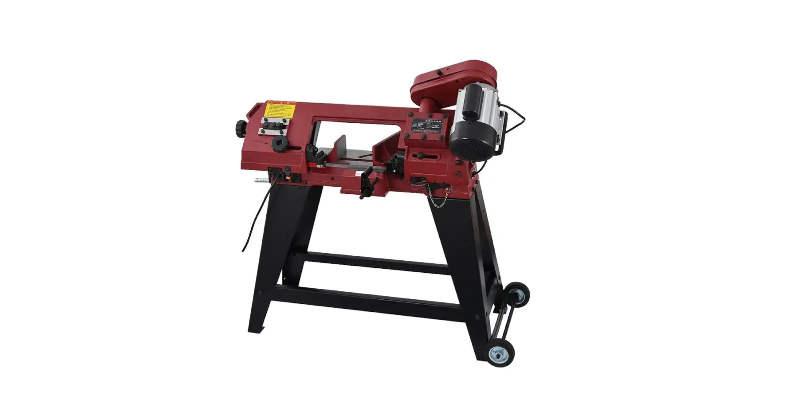
TOPMAQ GFW5012 Metal Band Saw Instruction Manual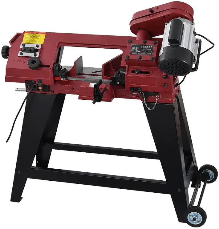
Technical Specification
Attention: Please choose proper power source, voltage and frequency that are shown in the l
| Metal band saw | GFW5012 |
| Motor Power | 550 W |
| Saw Blade | 1638X 12.7 X 0.65 mm |
| Cutting Capacity at 90 º | ● Φ115 mm ■ 115X115mm ▌100X140mm |
| Cutting Capacity at 45 º | ● Φ70 mm ■ 70X70mm ▌70X90mm |
| Cutting Angle Adjustment | 0—45 º |
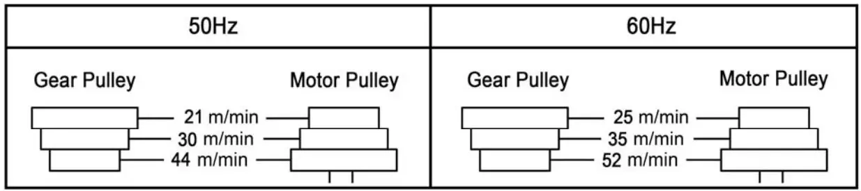
| Blade Speed | 50Hz: 21 / 30 / 44 m/min 60Hz: 25 / 35 / 52 m/min |
SAFETY
WARNING: To avoid electrical hazards, fire hazards, or damage to the tool, use proper circuit protection. Use a separate electrical circuit for your tools. To avoid shock or fire, replace power cord immediately if it is worn, cut or damaged in any way.
GENERAL SAFETY INSTRUCTIONS
WARNING: Read carefully these Operating Instructions. Familiarise with the controls and proper use of the machine. Keep the Operating Instructions for future reference. The warning labels with instructions attached to the machine provide important information on safe operation.
- READ and become familiar with the entire Operator’s Manual. LEARN thetool’s application, limitations and possible hazards.
- REMOVE ADJUSTING KEYS AND WRENCHES. Form a habit of checking to see that keys and adjusting wrenches are removed from the tool before turning ON.
- KEEP WORK AREA CLEAN. Cluttered areas and benches invite accidents.
- DON’T USE IN DANGEROUS ENVIRONMENT. Don’t use power tools in damp or wet locations, or expose them to rain. Keep work area well lighted.
- KEEP CHILDREN AWAY. All visitors should be kept at a safe distance from work area.
- MAKE WORKSHOP CHILDPROOF with padlocks.
- DON’T FORCE THE TOOL. It will do the job better and safer at the rate for which it was designed.
- USE THE RIGHT TOOL. Do not force tool or attachment to do a job for which it was not designed.
- USE PROPER EXTENSION CORD. Make sure your extension cord is in good condition. When using an extension cord, be sure to use one heavy enough to carry the current your product will draw. An undersized cord will result in a drop in line voltage and in loss of power that will cause the tool to overheat.
- WEAR PROPER APPAREL. Do not wear loose clothing, gloves, neckties, rings, bracelets, or other jewelry that may get caught in moving parts. Non-slip footwear is recommended. Wear protective hair covering to contain long hair.
- ALWAYS WEAR EYE PROTECTION. Wear goggles for protection against projected chips.
- DISCONNECT TOOLS before servicing; when changing blade and other part.
- USE RECOMMENDED ACCESSORIES. Consult the Operator’s Manual for recommended accessories. The use ofimproper accessories may cause serious injury.
- NEVER STAND ON TOOL. Serious injury could occur if the tool is tipped or if the cutting tool is unintentionally contacted.
- CHECK FOR DAMAGED PARTS. Before further use of the tool, a guard or other part that is damaged should be carefully checked to determine that it will operate properly and perform its intended function – check for alignment of moving parts, binding of moving parts, breakage of parts, mounting, and any other conditions that may affect its operation. A guard or other part that is damaged should be properly repaired or replaced.
- NEVER LEAVE TOOL RUNNING UNATTENDED. TURN POWER “OFF”. Don’t leave tool until it comes to a complete stop.
- DON’T OVERREACH. Keep proper footing and balance at all times.
- MAINTAIN TOOLS WITH CARE. Keep tools sharp and clean for best and safest performance. Follow instructions for lubricating and changing accessories.
- DO NOT use power tools in the presence of flammable liquids or gases.
- NEVER REMOVE GUARD, SAFETY DIVICES OR ART OF THE MACHINE.
- BE CAREFUL. Pay attention to what you are doing. Work reasonably. Do not use the machine when you are tired.
- HAVE YOUR MACHINE REPAIRED BY AN EXPERT ONLY! Thismachine meets the applicable safety provisions. Any repairs may only be executed by an expert, using original spare parts; otherwise, the user could face a risk of injury.
- Children and persons not familiarised with the machine and persons with limited physical, sensory and mental skills must not use the machine.
SPECIFIC SAFETY INSTRUCTIONS FOR THE MACHINE
- Secure the machine to floor before operating.
- The machine must be switched off before inserting material to be cut in the vice or before removing material to be cut from the vice.
- Keep your hands and fingers in a safe distance from the running saw blade atall times.
- The saw blade must not be broken by hand.
- Safety equipment and guards, etc, must not be removed.
- Never remove the cutting chips by hand. Use a brush at all times.
- Never leave the machine when in operation
ELECTRICAL REQUIREMENTS
POWER SUPPLY AND MOTOR SPECIFICATIONS
WARNING: To avoid electrical hazards, fire hazards, or damage to the tool, use proper circuit protection. Use a separate electrical circuit for your tools. To avoid shock or fire, if power cord is worn or cut, or damaged in any way, have it replaced immediately.
GROUNDING INSTRUCTIONS
WARNING: This tool must be grounded while in use to protect the operator from electrical shock.
IN THE EVENT OF A MALFUNCTION OR BREAKDOWN, grounding provides a path of least resistance for electric current and reduces the risk of electric shock. This tool is equipped with an electric cord that has an equipment-grounding conductor and a grounding plug. The plug MUST be plugged into a matching receptacle that is properly installed and grounded in accordance with ALL local codes and ordinances.
DO NOT MODIFY THE PLUG PROVIDED. If it will not fit the receptacle, have the proper receptacle installed by a qualified electrician.
IMPROPER CONNECTION of the equipment-grounding conductor can result in risk of electric shock. The conductor with green insulation (with or without yellow stripes) is the equipment-grounding conductor. If repair or replacement of the electric cord or plug is necessary, DO NOT connects the equipment-grounding conductor to a live terminal.
CHECK with a qualified electrician or service person if you do not completely understand the grounding instructions, or if you are not sure the tool is properly grounded.
Refer to nether picture: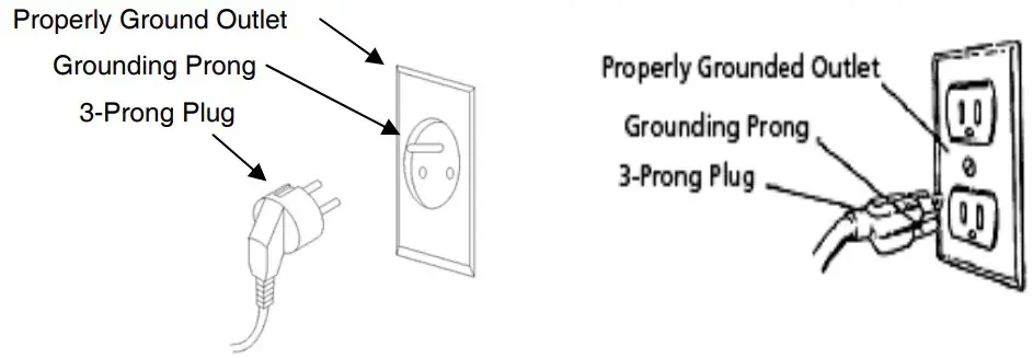
WARNING: Improper connection of equipment grounding conductor can result in the risk of electrical shock. Equipment should be grounded while in use to protect operator from electrical shock.
WARNING: This machine is for indoor use only. Do not expose to rain or use in damp locations.
GUIDELINES FOR EXTENSION CORDS
USE PROPER EXTENSION CORD. Make sure your extension cord is in good condition. When using an extension cord, be sure to use one heavy enough to carry the current your product will draw. An undersized cord will cause a drop in line voltage, resulting in loss of power and cause overheating.
Be sure your extension cord is properly wired and in good condition. Always replace a damaged extension cord or have it repaired by a qualified person before using it. Protect your extension cords from sharp objects, excessive heat and damp or wet areas.
ACCESSORIES AND ATTACHMENTS
RECOMMENDED ACCESSORIES
WARNING: To avoid injury:
- Use only accessories recommended for machine.
- Follow instructions that accompany accessories. Use of improper accessories may cause hazards.
- Use only accessories designed for this machine to avoid injury from thrown broken parts or work pieces.
- Do not use any accessory unless you have completely read the instruction or operator’s manual for that accessory.
CARTON CONTENTS
UNPACKING AND CHECKING CONTENTS
Carefully unpack the machine and all its parts, and compare against the illustration following.
WARNING:
- To avoid injury from unexpected starting, do not plug the power cord into a power source receptacle during unpacking and assembly. This cord must remain unplugged whenever you are assembling or adjusting the machine.
- If any part is missing or damaged, do not plug machine in until the missing or damaged part is replaced, and assembly is complete.
TABLE OF LOOSE PARTS
Unpack carton; check you machine to see parts listed below: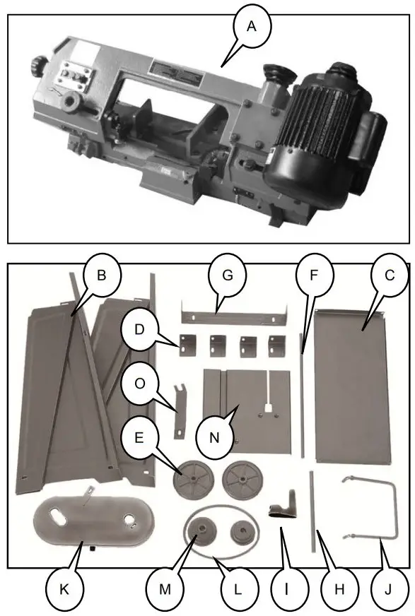
- A. Band saw X1
- B. Stand legs X2
- C. Tool tray X1
- D. Corner Support Braces X4
- E. Wheels X2
- F. Wheel mounting shaft X1
- G. Wheel Mounting Bracket X1
- H. Work Stop rod X1
- I. Work Stop X1
- J. Transport handle X1
- K. Pulley Cove X1
- L. V-Belt X1
- M. Pulleys with Keys X2
- N. Table X1
- O. Table Support X1
- P. Hardware bag (not shown)
ASSEMBLY
To assemble the band saw:
- Unfold the two stand leg assemblies, they are hinged on the edges for easy set up.
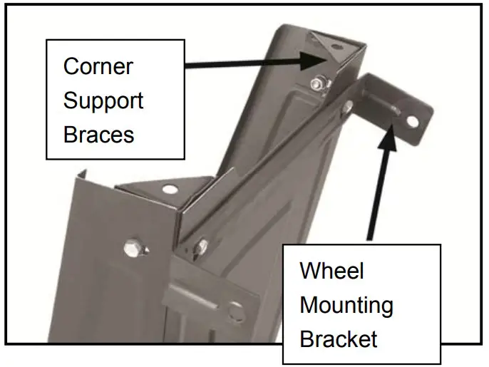
- Use the M6-1 x 12 hex bolts, M6-1 hex nuts, and 6mm flat washers to install the corner support braces in the bottom corners of the leg assemblies.
- On one of the leg assemblies, attach the wheel mounting bracket along with the corner support braces to the outside bottom edge.

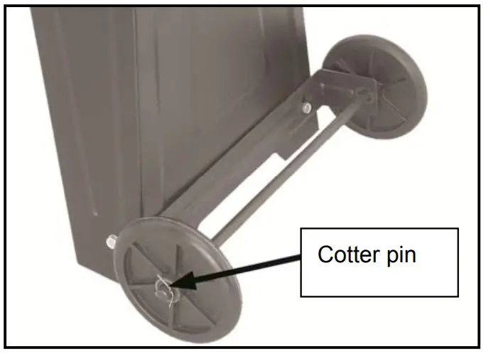
- Slide the wheel mounting shaft through the holes in the wheel mounting bracket.
- Slide the wheels onto the axle on the outside of the mounting brackets, and secure them with the cotter pins.

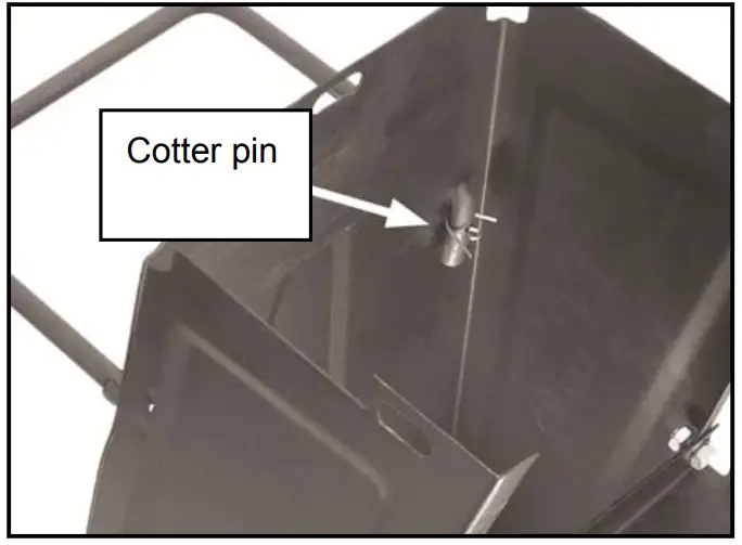
- On the other leg, insert the handle into the pre-drilled holes and secure it with the cotter pins.

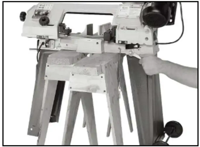
- With the help of an assistant, lift the band saw onto a pair of closely spaced sawhorses or other suitablesupport.
- Attach the legs to the band saw with the M8-1.25 x 25 hex bolts, 8mm flat washers, and M8-1.25 hex nuts.
- Remove the machine from the sawhorses, then install the tool tray in the middle of the stand with the M6-1 x 12 pan head screws, 6mm flat washers and M6-1 hex nuts.
- Check to see if the bands saw is relatively level, then final tighten all the nuts.

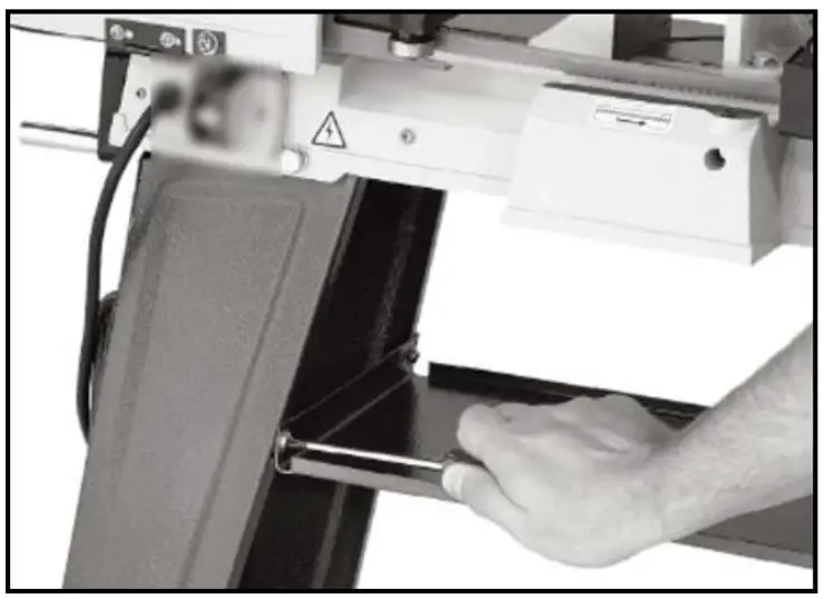
- Place the pulley cover over the motor and gear shafts, and secure it with the pre-installed M6-1 x 12 pan head screws and 6mm flat washers.

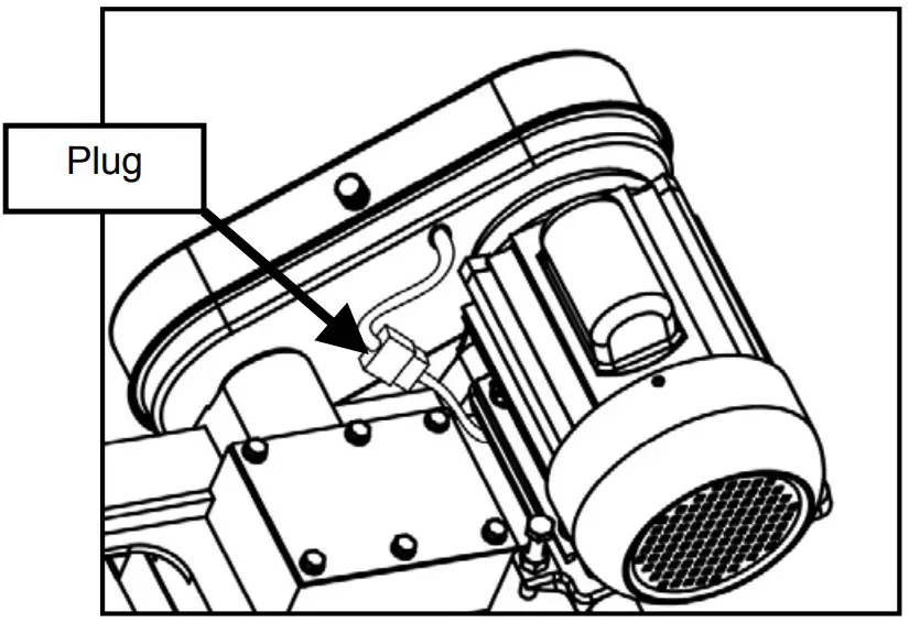
- Connect the two plugs together to make them firmly connection. (This plug is for the interlock switch in pulley cover. The interlock switch is an alternative part. If your machine has not this part, please skip the step.)

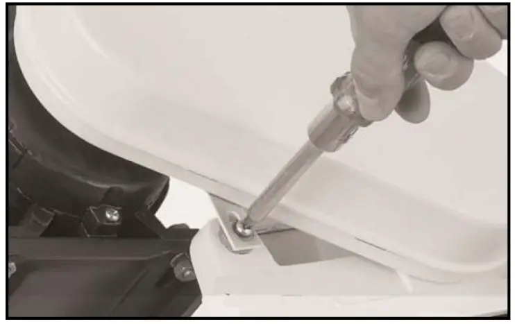
- Open the pulley cover and fix the pulley cover by using the pre-installed screw and washer.
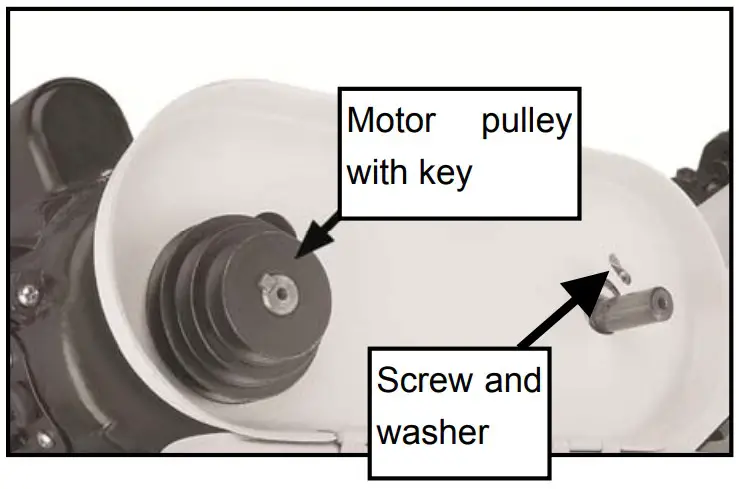
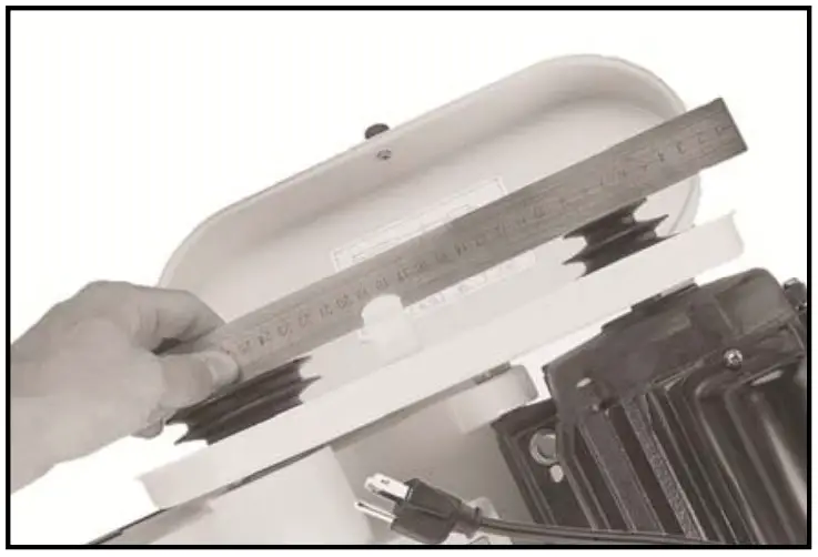
Insert the keys into the slots on the pulley shafts. Slide the large diameter motor pulley onto the motor shaft.
- Install the worm gear pulley with the small diameter wheel on the shaft closest to the gear box.
- Use a straightedge to check the alignment of the pulley wheels, and adjust them as needed.
- When the pulley wheels are aligned, tighten the set screws on both pulleys.

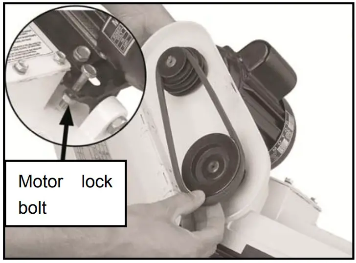
- Unthread the motor lock bolt, then pivot the motor up and slide the v-belt into the pulley grooves.
- Release the motor, letting its weight tension the v-belt, then thread the motor lock bolt against the side of the band saw.

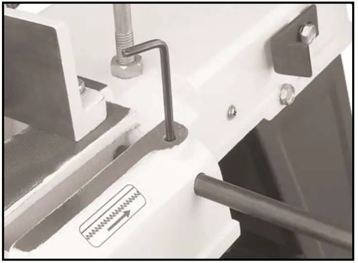
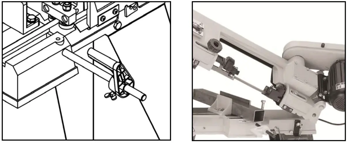
- Install the work stop shaft into the side of the band saw then lock it in place by tightening the set screw.

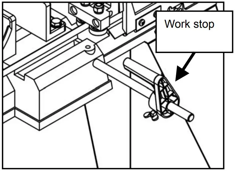
- Slide the work stop onto the end of the shaft and lock it into position.

ADJUSTMENTS
Warning: Turn off the machine and disconnect from the power supply before doing any adjustment.
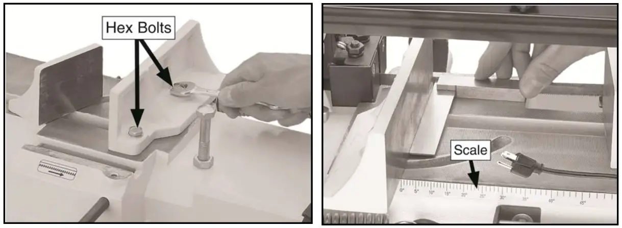
Vise adjustment
To use the vise:
- Loosen the two hex bolts.
Use the scale as a guide to set your angle or use a machinist square to set the angle of the vise, - Tighten the hex bolts.
- Loosen the hex bolt on the opposite jaw so the jaw can float, then match the angle of the workpiece and retighten the hex bolt.
- Tighten the vise against the workpiece.

Blade guides adjustment
Loosen the knob and slide the blade guide as close to the workpiece as possible, then re-tighten the knob.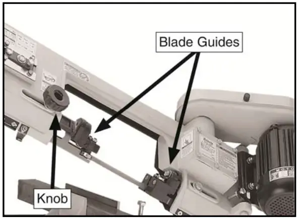
Feed rate adjustment
The feed rate is controlled by the spring and handle
To adjust the feed rate:
Slower: twist the handle clockwise to add tension to the spring.
Faster: twist the handle counterclockwise to remove tension from the spring.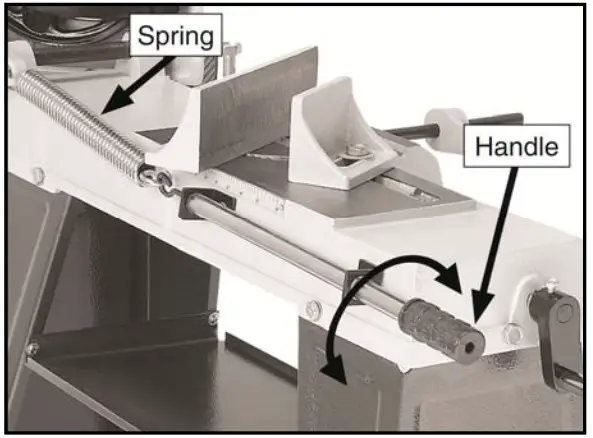
Blade speed adjustment.
The speed can easily be adjusted by changing the v-belt placement.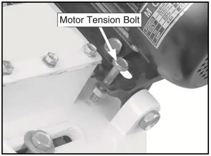
To change the blade speeds:
- Loosen the motor tension bolt to allow the motor to pivot
- Raise the motor to relieve the belt tension and position the belt in the desired pulley alignment.
- Release the motor and let its weight tension the belt.
- Tighten the motor tension bolt back against the frame of the band saw.

Head lock pin
The head locking pin safely secures the head in the down position. To ensure the head does not unexpectedly spring up and tip the band saw over, this locking pin must be properly inserted when the band saw is not in use or before moving it.
To use the head locking pin:
Fully lower the head down, then insert the locking pin through the holes in the headpivot arm and base,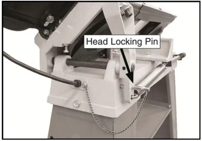
OPERATION
Horizontal Cutting
- Use the work stop to quickly and accurately cut multiple pieces of stock to the same length
- Clamp the material firmly in the vise jaws to ensure a straight cut through the material.
- Let the blade reach full speed before engaging the workpiece. Never start a cut with the blade in contact with the workpiece.
- Chips should be curled and silvery. If the chips are thin and powder like, increase your feed rate.
- If the chips are burned, reduce the blade speed.
- Wait until the blade has completely stopped before removing the workpiece from the vise, and avoid touching the cut end—it could be very hot!

Vertical Cutting
- Workpieces that cannot be properly supported or stabilized without a vise should not be cut in the vertical position
- Make sure that the vertical table assembly is securely fastened to the band saw frame so it will adequately support the workpiece.
- Always keep your fingers away from the blade
- Adjust the blade guides as close as possible to the workpiece to minimize side-to-side blade movement.

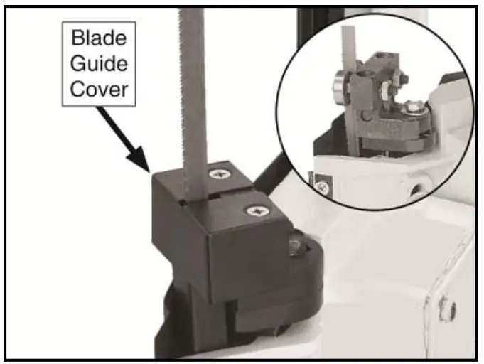
To assemble the bandsaw for vertical cutting:
- Disconnect band saw from power.
- Remove the two flat head screws and the blade guide cover
- Install the table and replace the two screws removed in Step 2.
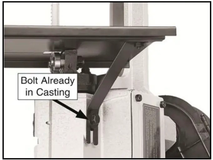
- Install the table bracket with the preinstalled hex bolt, the flat head screw, and hex nut.
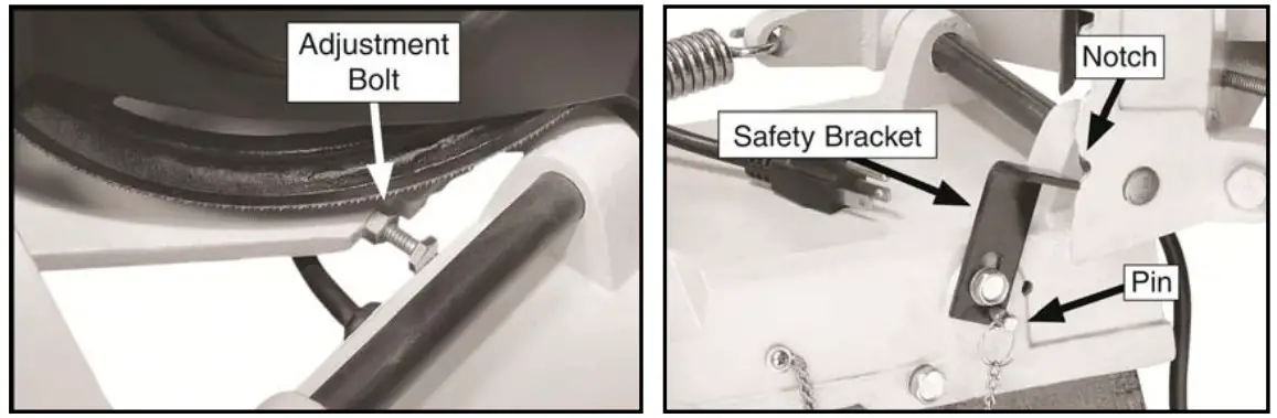
- Place a level on the table, then use the adjustment bolt to make the table level.
- Install the safety bracket and lock it in place with the pin to keep the saw from falling.

MAINTENANCE
Warning: Turn off the machine and disconnect from the power supply before conducting maintenance work or settings.
Change the saw blade
- Raise the head of the band saw to the vertical position, use the head locking pin to hold it in place,then remove the wheel access cover.
- Loosen the tension knob and slip the blade off of the wheels.
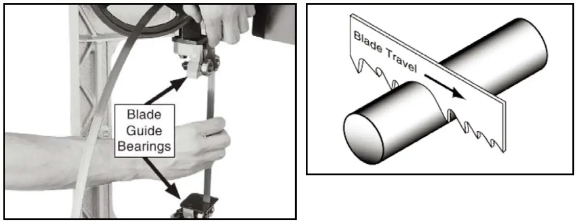
- Install the new blade through both blade guide bearings and around the bottom wheel, check to make sure the blade teeth are facing toward the work piece.
- Hold the blade around the bottom wheel with one hand and slip it around the top wheel with the other hand, keeping the blade between the blade guide bearings.
- Tighten the tension knob so the blade will not slip on the wheels upon start up.

Machine care
- Usually check the condition of the power supply cords and replace them if they are broken, or even worse if the internal wires are shown.
- Use a brush and a shop vacuum to remove chips and other debris from the machine.
- Always keep the machine handgrip clean to prevent accidental slipping during use.
- Remove the processing residues from the cutting area and the blade guides whenever necessary.
- If you do not intend to use the sawing machine for a long time, clean it and put it in a dry place if possible. In these cases it is advisable to slacken off the blade so that it is not kept for any reason.
- To ensure effective machine operation, check the condition of the blade daily and sharpen it whenever necessary.
TROUBLESHOOTHING
| PROBLEM | CAUSE | SOLUTION |
| The motor does not work |
|
|
| Machine stalls or is underpowered. |
|
|
| Machine has vibration or noisy operation. |
|
|
| Teeth are ripping from the blade. |
|
|
| Inaccurate cut squaring |
|
|
| The blade tends to protrude from the guide |
|
|
ASSEMBLY DIAGRAM
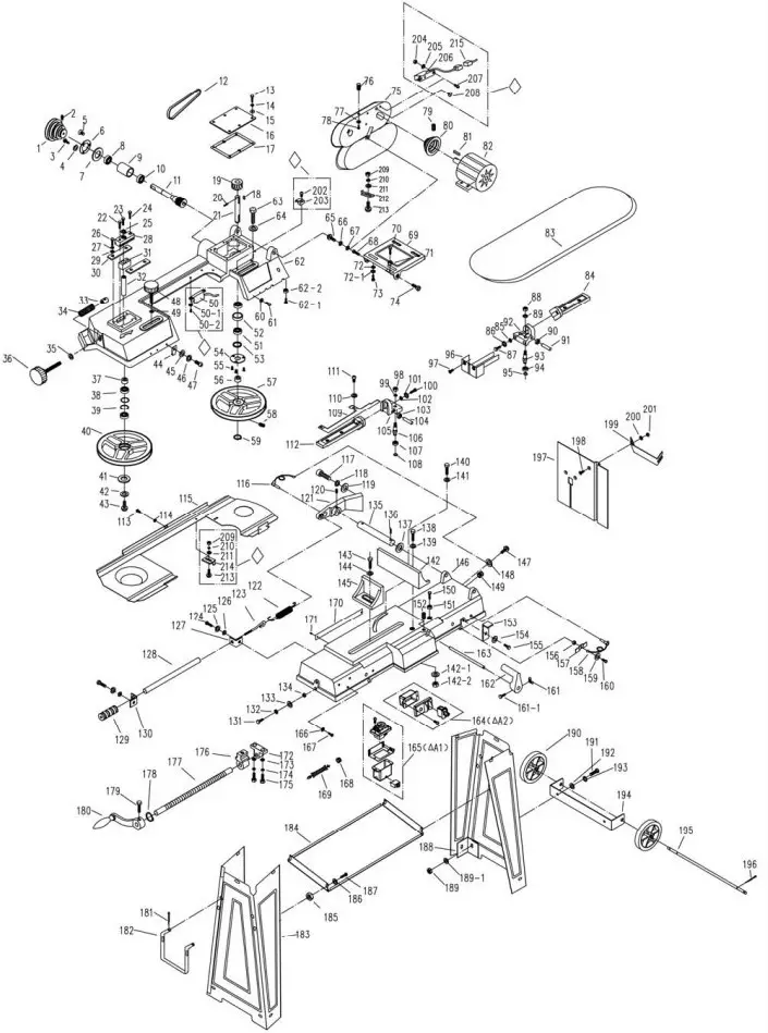
PART LIST
| NO. | DESCRIPTION | QTY |
| 1 | Worm shaft pulley | 1 |
| 2 | Set screw | 1 |
| 3 | Pan head screw | 2 |
| 4 | Flat washer | 2 |
| 5 | Flat head screw | 1 |
| 6 | Bearing cover | 1 |
| 7 | Oil seal | 1 |
| 8 | Ball bearing | 1 |
| 9 | Bearing bushing | 1 |
| 10 | Ball bearing | 1 |
| 11 | Worm gear | 1 |
| 12 | V belt | 1 |
| 13 | Hex head bolt | 6 |
| 14 | Lock washer | 6 |
| 15 | Flat washer | 6 |
| 16 | Gear box cover | 1 |
| 17 | Gear box gasket | 1 |
| 18 | Key | 2 |
| 19 | Worm gear | 1 |
| 20 | Spring pin | 1 |
| 21 | Worm gear shaft | 1 |
| 22 | Hex head bolt | 1 |
| 23 | Hex head bolt | 1 |
| 24 | Hex head bolt | 1 |
| 25 | Flat washer | 1 |
| 26 | Hex head bolt | 4 |
| 27 | Lock washer | 4 |
| 28 | Sliding block | 1 |
| 29 | Flat washer | 4 |
| 30 | Guide plate | 2 |
| 31 | Shaft block | 1 |
| 32 | Shaft | 1 |
| 33 | Blade tension nut | 1 |
| 34 | Spring | 1 |
| 35 | Flat washer | 1 |
| 36 | Blade tension knob | 1 |
| 37 | Bushing | 1 |
| 38 | Ball bearing | 1 |
| 39 | Retaining ring | |
| 40 | Rear blade wheel | 1 |
| 41 | Flat washer | 1 |
| 42 | Lock washer | 1 |
| 43 | Socket head screw | 1 |
| 44 | Switch cut off finger | 1 |
| 45 | Flat washer | 1 |
| 46 | Lock washer | 1 |
| 47 | Hex head screw | 1 |
| 48 | Rear guide tighten knob | 1 |
| 49 | Flat washer | 1 |
| 50 | Interlock switch assembly | 1 |
| 50-1 | Flat washer | 2 |
| 50-2 | Pan head screw | 2 |
| 51 | Ball bearing | 2 |
| 52 | Bushing | 1 |
| 53 | Oil seal | 1 |
| 54 | Bearing cover | 1 |
| 55 | Flat head screw | 3 |
| 56 | Bushing | 1 |
| 57 | Front blade wheel | 1 |
| 58 | Set screw | 1 |
| 59 | Retaining ring | 1 |
| 60 | Flat washer | 4 |
| 61 | Pan head screw | 4 |
| 62 | Frame | 1 |
| 62-1 | Hex head bolt | 1 |
| 62-2 | Hex nut | 1 |
| 63 | Hex head bolt | 1 |
| 64 | Flat washer | 1 |
| 65 | Pan head screw | 1 |
| 66 | Lock washer | 1 |
| 67 | Flat washer | 1 |
| 68 | Hex head bolt | 1 |
| 69 | Motor support plate | 1 |
| 70 | Hex head bolt | 1 |
| 71 | Hex nut | 1 |
| 72 | Flat washer | 4 |
| 72-1 | Lock washer | 4 |
| 73 | Hex head bolt | 4 |
| 74 | Hex head bolt | 1 |
| 75 | Belt cover | 1 |
| 76 | Knob | 1 |
| 77 | Flat washer | 1 |
| 78 | Pan head screw | 1 |
| 79 | Set screw | 2 |
| 80 | Motor pulley | 1 |
| 81 | Key | 1 |
| 82 | Motor | 1 |
| 83 | Blade | 1 |
| 84 | Front guide base | 1 |
| 85 | Flat washer | 1 |
| 86 | Lock washer | 1 |
| 87 | Hex head bolt | 1 |
| 88 | Hex nut | 2 |
| 89 | Lock washer | 2 |
| 90 | Ball bearing | 1 |
| 91 | Shaft | 1 |
| 92 | Front blade guide | 1 |
| 93 | Shaft | 2 |
| 94 | Ball bearing | 1 |
| 95 | Retaining ring | 2 |
| 96 | Front blade guard | 1 |
| 97 | Flat head screw | 2 |
| 98 | Hex nut | 2 |
| 99 | Lock washer | 2 |
| 100 | Hex head bolt | 1 |
| 101 | Lock washer | 1 |
| 102 | Flat washer | 1 |
| 103 | Ball bearing | 1 |
| 104 | Shaft | 1 |
| 105 | Rear blade guide | 1 |
| 106 | Shaft | 2 |
| 107 | Ball bearing | 1 |
| 108 | Retaining ring | 2 |
| 109 | Rear blade guard | 1 |
| 110 | Flat washer | 2 |
| 111 | Pan head screw | 2 |
| 112 | Rear guide base | 1 |
| 113 | Pan head screw | 1 |
| 114 | Flat washer | 1 |
| 115 | Frame guard | 1 |
| 116 | Pin with chain | 1 |
| 117 | Socket head screw | 2 |
| 118 | Lock washer | 2 |
| 119 | Flat washer | 2 |
| 120 | Set screw | 1 |
| 121 | Pivot block | 1 |
| 122 | Spring | 1 |
| 123 | Spring adjusting screw | 1 |
| 124 | Hex head bolt | 2 |
| 125 | Lock washer | 2 |
| 126 | Flat washer | 2 |
| 127 | Screw support plate | 1 |
| 128 | Adjusting rod | 1 |
| 129 | Knob | 1 |
| 130 | Adjusting rod support | 1 |
| 131 | Hex head bolt | 2 |
| 132 | Lock washer | 2 |
| 133 | Flat washer | 2 |
| 134 | Hex nut | 2 |
| 135 | Pivoting rod | 1 |
| 136 | Spring pin | 1 |
| 137 | Flat washer | 1 |
| 138 | Hex head bolt | 1 |
| 139 | Flat washer | 1 |
| 140 | Hex head bolt | 1 |
| 141 | Flat washer | 1 |
| 142 | Vise jaw | 1 |
| 142-1 | Flat washer | 1 |
| 142-2 | Hex nut | 1 |
| 143 | Hex head bolt | 1 |
| 144 | Flat washer | 1 |
| 145 | Sliding vise jaw | 1 |
| 146 | Base | 1 |
| 147 | Pan head screw | 1 |
| 148 | Flat washer | 1 |
| 149 | Bushing | 2 |
| 150 | Hex head bolt | 1 |
| 151 | Hex nut | 1 |
| 152 | Set screw | 1 |
| 153 | Safety bracket | 1 |
| 154 | Flat washer | 1 |
| 155 | Hex head bolt | 1 |
| 156 | Hex nut | 1 |
| 157 | Cord clamp | 1 |
| 158 | Pin with chain | 1 |
| 159 | Flat washer | 1 |
| 160 | Pan head screw | 1 |
| 161 | Wing nut | 1 |
| 161-1 | Hex head bolt | 1 |
| 162 | Work stop | 1 |
| 163 | Work stop rod | 1 |
| 164 | Lock switch assembly | 1 |
| 165 | Magnetic switch assembly | 1 |
| 166 | Serriated washer | 2 |
| 167 | Pan head screw | 2 |
| 168 | Bushing | 1 |
| 169 | Power cord | 1 |
| 170 | Angle scale | 1 |
| 171 | Rivet | 2 |
| 172 | Screw support block | 1 |
| 173 | Flat washer | 2 |
| 174 | Lock washer | 2 |
| 175 | Hex head bolt | 2 |
| 176 | Vise nut | 1 |
| 177 | Lead screw | 1 |
| 178 | Retaining ring | 1 |
| 179 | Hex head bolt | 1 |
| 180 | Crank handle | 1 |
| 181 | cotter pin | 2 |
| 182 | Transport handle | 1 |
| 183 | Leg assembly | 2 |
| 184 | Connecting plate | 1 |
| 185 | Hex nut | 4 |
| 186 | Flat washer | 4 |
| 187 | Pan head screw | 4 |
| 188 | Leg corner | 4 |
| 189 | Hex nut | 8 |
| 189-1 | Flat washer | 8 |
| 190 | Transport wheel | 2 |
| 191 | Hex head bolt | 8 |
| 192 | Flat washer | 8 |
| 193 | Lock washer | 8 |
| 194 | Wheel stand | 1 |
| 195 | Shaft | 1 |
| 196 | cotter pin | 4 |
| 197 | Table | 1 |
| 198 | Flat head screw | 2 |
| 199 | Table support | 1 |
| 200 | Flat washer | 2 |
| 201 | Hex nut | 2 |
| 202 | Pan head screw | 1 |
| 203 | Cord clamp | 1 |
| 204 | Hex nut | 2 |
| 205 | Flat washer | 2 |
| 206 | Interlock switch assembly | 1 |
| 207 | Pan head screw | 2 |
| 208 | Bushing | 1 |
| 209 | Hex nut | 2 |
| 210 | Lock washer | 2 |
| 211 | Flat washer | 2 |
| 212 | Switch operating finger | 1 |
| 213 | Pan head screw | 2 |
| 214 | Switch operating finger | 1 |
| 215 | Line with connector | 1 |


