![]()
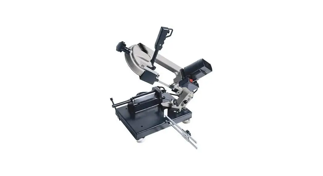
Metal Cutting Band Saw
Owner’s Manual
 WARNING: Read carefully and understand all ASSEMBLY AND OPERATION INSTRUCTIONS before operating. Failure to follow the safety rules and other basic safety precautions may result in serious personal injury.
Item #101670
READ & SAVE THESE INSTRUCTIONS
Thank you very much for choosing a Klutch® product!
For future reference, please complete the owner’s record below:
Serial Number/Lot Date Code (if applicable): _____________________
Purchase Date: ____________________________________________
Save the receipt, warranty, and this manual. It is important that you read the entire manual to become familiar with this product before you begin using it.
This product is designed for certain applications only. Northern Tool & Equipment is not responsible for issues arising from modification or improper use of this product such as an application for which it was not designed. We strongly recommend that this product not be modified and/or used for any application other than that for which it was designed.
For technical questions, please call 1-800-222-5381.
Intended Use
This Klutch® Benchtop Metal Cutting Band Saw is a compact yet powerful metal cutting band saw that’s easy to move right where you need it.
Packaging Contents
- Metal band saw (1)
- Foot (4)
- Work stop with lock handle (1)
- Guide rail with hex nut (1)
- Manual (1)
Technical Specifications
| Property | Specification |
| Motor | 120V 60Hz 4.5A S6 40% |
| Saw blade size | 1435×12.7×0.65mm |
| Saw blade teeth | 8/12 teeth per inch |
| Cutting capacity at circular material | 90 127x125mm, 45 80x100mm |
| Cutting angle adjustment | 0-60 |
| Blade speed | 125-260FPM (38-80 m/min) |
Important Safety Information
⚠WARNING
- Read and understand all instructions. Failure to follow all instructions may result in serious injury or property damage.
- The warnings, cautions, and instructions in this manual cannot cover all possible conditions or situations that could occur. Exercise common sense and caution when using this tool. Always be aware of the environment and ensure that the tool is used in a safe and responsible manner.
- Do not allow persons to operate or assemble the product until they have read this manual and have developed a thorough understanding of how it works.
- Do not modify this product in any way. Unauthorized modification may impair the function and/or safety and could affect the life of the product. There are specific applications for which the product was designed.
- Use the right tool for the job. DO NOT attempt to force small equipment to do the work of larger industrial equipment. There are certain applications for which this equipment was designed. It will be a safer experience and do the job better at the capacity for which it was intended. DO NOT use this equipment for a purpose for which it was not intended.
- Industrial or commercial applications must follow OSHA requirements.
⚠WARNING
PROP 65
- This product can expose you to chemicals including lead, which is known to the State of California to cause cancer. For more information, go to www.p65warnings.ca.gov.
- Some dust created by power sanding, sawing, grinding, drilling, and other construction activities contain chemicals known to the state of California to cause cancer, birth defects, or other reproductive harm. Some examples of these chemicals are:
– lead from lead-based paints,
– crystalline silica from bricks and cement and other masonry products, and
– arsenic and chromium from chemically treated lumber. - Your risk from these exposures varies depending on how often you do this type of work. To reduce your exposure to these chemicals, work in a well-ventilated area, and work with approved safety equipment, such as dust masks that are specially designed to filter out microscopic particles.
- Handling power cords on corded products may expose you to lead, a chemical is known to the state of California to cause cancer and birth defects or other reproductive harm. Wash your hands after handling.
⚠WARNING
WORK AREA SAFETY
- Inspect the work area before each use. Keep work area clean, dry, free of clutter, and well-lit. Cluttered, wet, or dark work areas can result in injury. Using the product in confined work areas may put you dangerously close to cutting tools and rotating parts.
- Do not use the product where there is a risk of causing a fire or an explosion; e.g., in the presence of flammable liquids, gases, or dust. The product can create sparks, which may ignite flammable liquids, gases, or dust.
- Do not allow the product to come into contact with an electrical source. The tool is not insulated and contact will cause electrical shock.
- Keep children and bystanders away from the work area while operating the tool. Do not allow children to handle the product.
- Be aware of all power lines, electrical circuits, water pipes, and other mechanical hazards in your work area. Some of these hazards may be hidden from your view and may cause personal injury and/or property damage if contacted.
⚠WARNING
PERSONAL SAFETY
- Stay alert, watch what you are doing, and use common sense when operating the tool. Do not use the tool while you are tired or under the influence of drugs, alcohol, or medication. A moment of inattention while operating the tool may result in serious personal injury.
- Dress properly. Do not wear loose clothing, dangling objects, or jewelry. Keep your hair, clothing, and gloves away from moving parts. Loose clothes, jewelry, or long hair can be caught in moving parts. Air vents on the tool often cover moving parts and should be avoided.
- Wear the proper personal protective equipment when necessary. Use ANSI Z87.1 compliant safety goggles (not safety glasses) with side shields, or when needed, a face shield. Use a dust mask in dusty work conditions. Also use non-skid safety shoes, hardhat, gloves, dust collection systems, and hearing protection when appropriate. This applies to all persons in the work area.
- Do not overreach. Keep proper footing and balance at all times.
⚠CAUTION
PRODUCT USE AND CARE
- Do not force the product. Products are safer and do a better job when used in the manner for which they are designed. Plan your work and use the correct product for the job.
- Check for damaged parts before each use. Carefully check that the product will operate properly and perform its intended function. Replace damaged or worn parts immediately. Never operate the product with a damaged part.
- Store the product when it is not in use. Store it in a dry, secure place out of the reach of children. Inspect the tool for good working condition prior to storage and before re-use.
- Use only accessories that are recommended by the manufacturer for use with your product. Accessories that may be suitable for one product may create a risk of injury when used with another tool. Never use an accessory that has a lower operating speed or operating pressure than the tool itself.
- Keep guards in place and in working order. Never operate the product without the guards in place.
Grounding
⚠WARNING
- This machine must be grounded while in use to protect the operator from electrical shock. This unit is equipped with an electrical cord that has an equipment grounding conductor and a grounding plug. The plug MUST be plugged into a matching receptacle that is properly installed and grounded in accordance with ALL local codes and ordinances.
- DO NOT MODIFY THE PROVIDED PLUG. If it will not fit the receptacle, have the proper receptacle installed by a qualified electrician.
CHECK with a qualified electrician or service person if you do not completely understand the grounding instructions, or if you are not sure the tool is properly grounded.
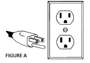
Grounded Tools: Tools with 3-Prong Plugs
Tools marked with Grounding Required have a 3-wire cord and 3-prong grounding plug. The plug must be connected to a properly grounded outlet. If the tool should electrically malfunction or break down, grounding provides a low resistance path to carry electricity away from the user, reducing the risk of electric shock. (See Figure A.)
The grounding prong in the plug is connected through the green wire inside the cord to the grounding system in the tool. The green wire in the cord must be the only wire connected to the tool’s grounding system and must never be attached to an electrically live terminal.
Your tool must be plugged into an appropriate outlet, properly installed, and grounded in accordance with all codes and ordinances. The plug and outlet should look like those in the following illustration.
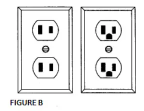
Double Insulated Tools: Tools with Two-Prong Plugs
Tools marked Double Insulated do not require grounding. They have a special double insulation system that satisfies OSHA requirements and complies with the applicable standards of Underwriters Laboratories, Inc., the Canadian Standard Association, and the National Electrical Code. (See Figure B.)
Double insulated tools may be used in either of the 120-volt outlets shown in the following illustration.
Extension Cords
⚠WARNING
- USE A PROPER EXTENSION CORD. Make sure your extension cord is in good condition. When using an extension cord, be sure to use one heavy enough to carry the current your product will draw. An undersized cord will cause a drop in line voltage, resulting in loss of power and cause overheating.
- Be sure your extension cord is properly wired and in good condition. Always replace a damaged extension cord or have it repaired by a qualified person before using it. Protect your extension cords from sharp objects, excessive heat, and damp or wet areas.
- Grounded tools require a 3-wire extension cord. Double Insulated tools can use either a 2- or 3wire extension cord.
- As the distance from the supply outlet increases, you must use a heavier gauge extension cord. Using extension cords with inadequately sized wire causes a serious drop in voltage, resulting in loss of power and possible tool damage.
- The smaller the wire’s gauge number, the greater the capacity of the cord. For example, a 14gauge cord can carry a higher current than a 16-gauge cord. The minimum extension cord wire size is shown in the following table:
Minimum Wire Size Of Extension Cords | ||||
Nameplate AMPS | Cord Length | |||
| 25′ | 50′ | 100′ | 150′ | |
| 0-6 | 18 AWG | 16 AWG | 16 AWG | 14 AWG |
| 6-10 | 18 AWG | 16 AWG | 14 AWG | 12 AWG |
| 10-12 | 16 AWG | 16 AWG | 14 AWG | 12 AWG |
| 12-16 | 14 AWG | 12 AWG | NOT RECOMMENDED | |
- When using more than one extension cord to make up the total length, make sure each cord contains at least the minimum wire size required.
- If you are using one extension cord for more than one tool, add the nameplate amperes and use the sum to determine the required minimum cord size.
- If you are using an extension cord outdoors, make sure it is marked with the suffix W-A (W in Canada) to indicate it is acceptable for outdoor use.
- Make sure your extension cord is properly wired and in good electrical condition. Always replace a damaged extension cord or have it repaired by a qualified electrician before using it.
- Protect your extension cords from sharp objects, excessive heat, and damp or wet areas.
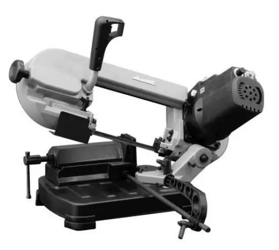
Main Parts of Product
Subassembly
Metal band saw
Work stop with lock handle
Foot (4)
Guide rail with hex nut
Assembly Instructions
⚠WARNING
Read the ENTIRE MANUAL – IMPORTANT SAFETY INFORMATION: Read all sections of this manual including all text under subheadings therein before set-up or use of this product.
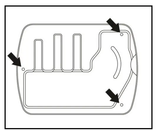
- Slide the four rubber feet onto the base of the saw.
- Place the band saw on a workbench or the optional band saw stand item 101740 and secure with the three bolts.

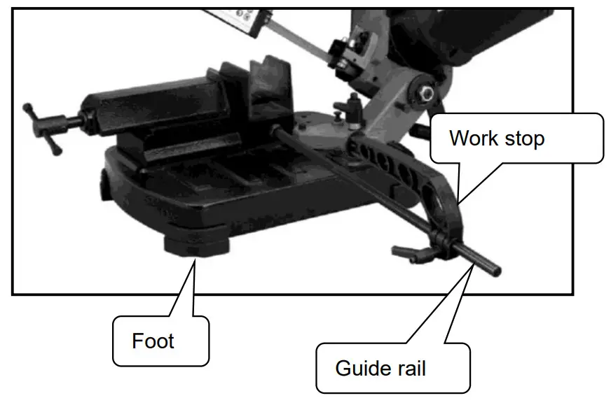
- Screw the guide rail to the threaded hole on the vise base. Tighten the nut to fix it.
- Attach the work stop to the guide rail. Secure it by tightening the lock handle.

Before Each Use
⚠WARNING
- Make sure the band saw is securely fastened down.
- Make sure all safety guards are installed and positioned correctly.
- Make sure the blade is tensioned appropriately.
Positioning the work stop
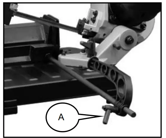
Use the work stop if you have to do several cuts on pieces of the same length.
- Loosen the lock handle A and place the work stop at the desired distance from the blade.
- Retighten the lock handle.
![]() CAUTION
CAUTION
Make sure that the work stop does not interfere with the downward movement of the blade!
Cutting angle adjustment
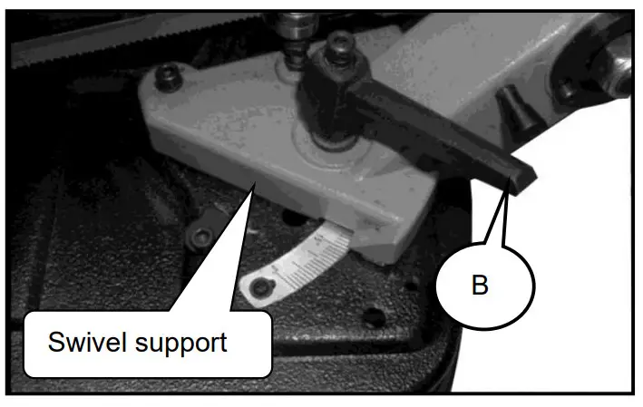
The band saw can cut at angles from 0º to 60º.
- Loosen the lock handle B.
- Turn the swivel support until the mark on support matches desired angle on the scale.
- Retighten the locking handle.
CAUTION! Make sure the lock handle B has been tightened before turning on the machine.
![]() CAUTION
CAUTION
Make sure the lock handle B has been tightened before turning on the machine.
Adjusting the blade guide
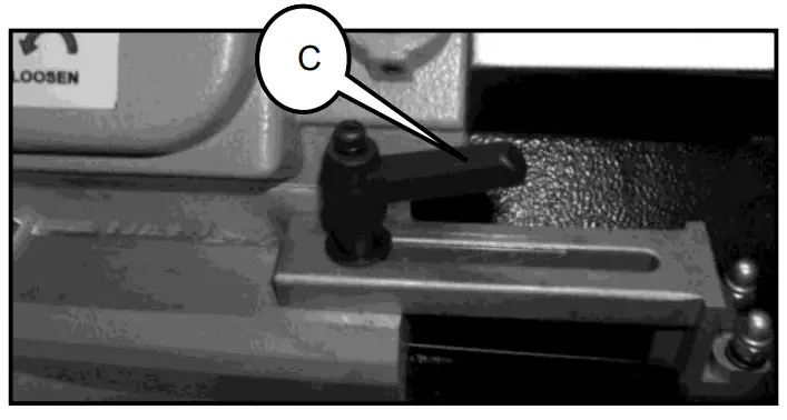
The sliding blade guide must be adjusted to bring the guide close to the material. If the adjustment is not done, it will result in an unclean cut.
- Loosen the lock handle C.
- Slide the blade guide to move it closer to the workpiece.
- Retighten the lock handle C.
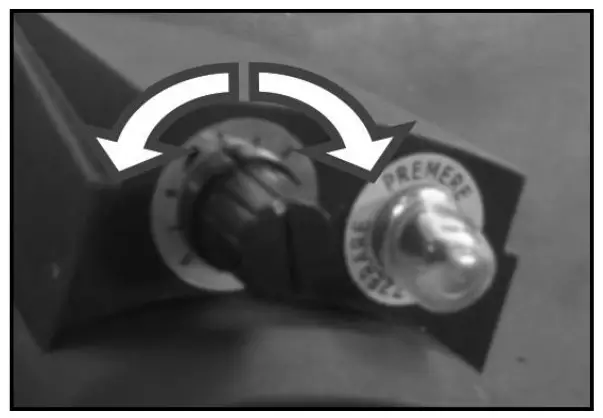
Set cutting speed
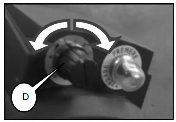
The cutting speed always depends on the material being cut.
- Turn the control knob D to increase or decrease the speed as required.
Sample speeds:
Common steel: 40-60m/min
Aluminum, alloy: 80m/min
Pipes/sections: 70-80m/min
Operating Instructions
⚠WARNING
- The machine must be switched off before inserting material to be cut in the vice or before removing material to be cut from the vice.
- Keep your hands and fingers at a safe distance from the running saw blade at all times.
- Safety equipment and guards, etc, must not be removed.
- Never remove the cutting chips by hand. Use a brush at all times.
- Never leave the machine when in operation.
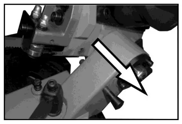
- Pull out the locking pin from the hole in the body and tilt the saw body to the upper position.

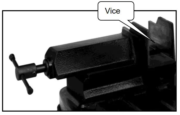
- Use the vice to securely clamp the workpiece.

- Check workpiece stop and cutting speed adjustments.

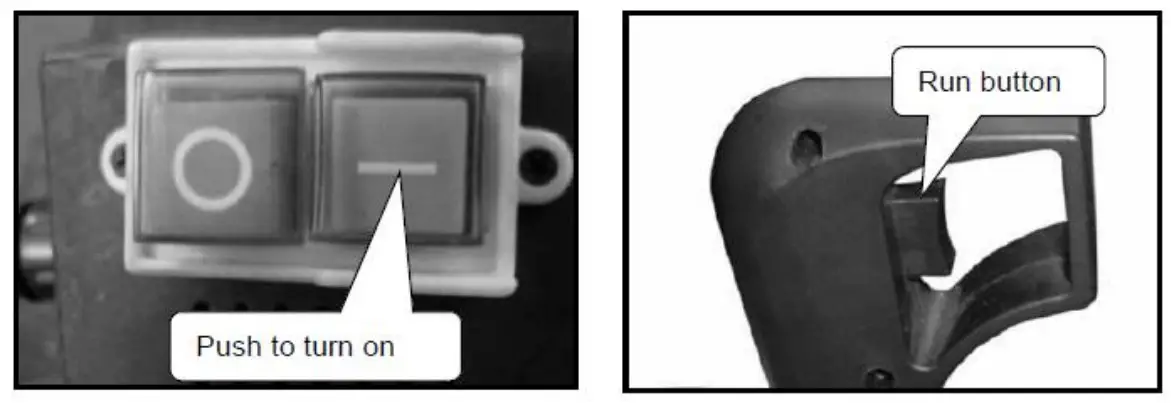
- Push the green button to turn on the main switch. Using the index finger of your right hand, press the run button.

- Gradually lower the machine body until it comes lightly into contact with the workpiece. Now begin to apply gradual pressure on the workpiece and complete the cut.
Maintenance
⚠WARNING
Always wear protective gauntlets before changing the saw blade!
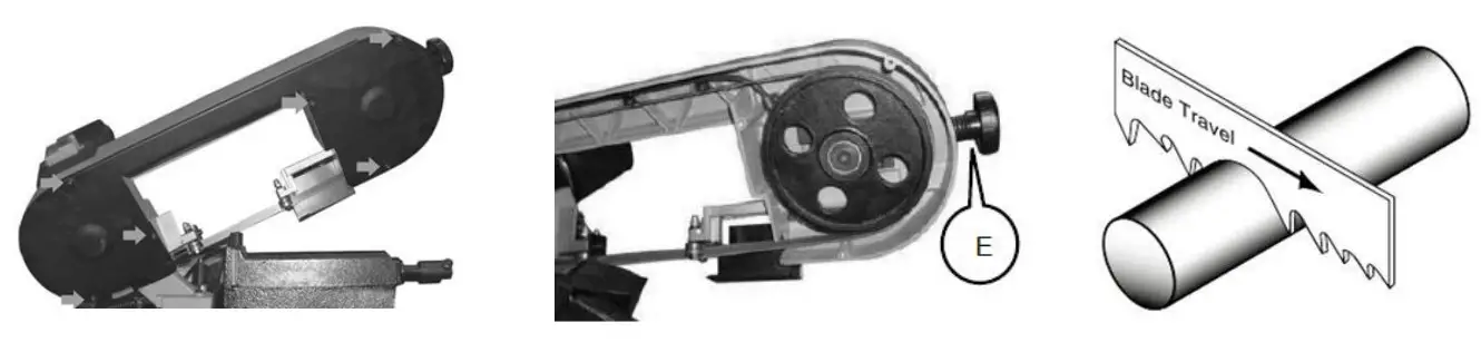
Changing the Saw Blade
- Remove the protective casing unscrewing the six screws.
- Loosen the blade tension, turning the knob E in the anti-clockwise direction.
- Extract the blade first from the guides and then from the cast iron pulleys.
- Insert the new blade first between the guides and then into the cast iron pulleys, checking to make sure the blade teeth are facing toward the workpiece.
- Turn the knob E to adjust the blade tension.
- Replace the protective casing.
- Reposition the blade guides in the correct position for the next cut.
 Maintain the product by adopting a program of conscientious repair and maintenance in accordance with the following recommended procedures. It is recommended that the general condition of any tool be examined before it is used. Keep your tool in good repair. Keep all cutting tools sharp and clean. Properly maintained cutting tools with sharp cutting edges are less likely to bind and are easier to control. Keep handles dry, clean, and free from oil and grease. Also, refer to the engine manufacturer’s instruction manual for additional information about engine maintenance. The following chart is based on a normal operating schedule.
Maintenance Interval Maintenance Point Every 3 months Check the blade for dullness and replace if necessary. Every 2 months Usually check the condition of the power supply cords and replace them if they are broken, or even worse if the internal wires are shown. Use a brush and a shop vacuum to remove chips and other debris from the machine.
Always keep the machine handgrip clean to prevent accidental slipping during use.
Remove the processing residues from the cutting area and the blade guides whenever necessary.
If you do not intend to use the band saw for a long time, clean it and put it in a dry place if possible. In this case, it is advisable to reduce tension on the blade.
To ensure effective machine operation, check the condition of the blade daily and sharpen or replace it whenever necessary.
 Maintain the product by adopting a program of conscientious repair and maintenance in accordance with the following recommended procedures. It is recommended that the general condition of any tool be examined before it is used. Keep your tool in good repair. Keep all cutting tools sharp and clean. Properly maintained cutting tools with sharp cutting edges are less likely to bind and are easier to control. Keep handles dry, clean, and free from oil and grease. Also, refer to the engine manufacturer’s instruction manual for additional information about engine maintenance. The following chart is based on a normal operating schedule.
Troubleshooting
Use the table below to troubleshoot problems before contacting service personnel or your local dealer. If the problem continues after troubleshooting, call your local dealer for assistance.
Failure | Possible Cause | Corrective Action |
| The motor does not work | Defective motor, power cable, or plug. The overload cutout has tripped. | Check the machine and reset the overload cutout. |
| Overload cutout tripped | Motor overload is caused by excessive cutting pressure. Motor breakdown. | Perform the cut on the piece at the correct pressure. |
| Inaccurate cut squaring | Excessive cutting pressure. Incorrect blade tooth in relation to the workpiece. Incorrect adjustment of the sliding blade guide. Incorrect cutting speed in relation to the workpiece. The workpiece is wrongly positioned in the vice. Poor blade tension. | Decrease cutting pressure. Choose a proper blade for the workpiece. Check blade guide adjustment. Adjust to correct cutting speed. Check workpiece positioning and clamping in the vice. Check blade tension. |
| The blade tends to protrude from the guide | Excessive blade tension. Incorrect eccentric blade guide adjustment. The blade slips on the pulleys, caused by oil or grease required for cutting operations. | Check blade tension Check eccentric blade guide adjustment Never use any type of lubricant or coolant for the cutting operations; specialized personnel should check and replace the pulleys, if necessary. |
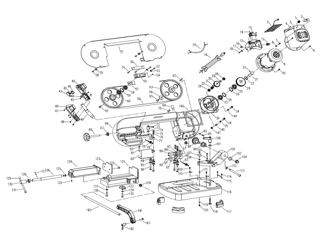
Parts Diagram
| Reference | Part Number | Part Description | Quantity |
| 1 | 1 | Speed adjusting knob | 1 |
| 2 | 2 | Circuit breaker | 1 |
| 3 | 3 | Motor housing | 1 |
| 4 | 4 | 2.9-1X13mm Thread forming screw | 2 |
| 5 | 5 | Motor driver | 1 |
| 6 | 6 | M4X8mm Pan head screw | 3 |
| 7 | 7 | M4X8mm Pan head screw | 1 |
| 8 | 8 | 4mm Serrated washer | 1 |
| 9 | 9 | Motor assembly | 1 |
| 10 | 10 | M5X10mm Socket head screw | 4 |
| 11 | 12 | Strain relief | 1 |
| 12 | 13 | Switch | 1 |
| 13 | 14 | 2.9-1X9.5mm Thread forming screw | 2 |
| 14 | 15 | Switch box | 1 |
| 15 | 16 | Indicator light | 1 |
| 16 | 17 | 4mm Flat washer | 2 |
| 17 | 18 | 2.9-1X16mmThread forming screw | 2 |
| 18 | 19 | Power cord | 1 |
| 19 | 20 | Inner line | 1 |
| 20 | 21 | Front-wheel shaft | 1 |
| 21 | 22 | 5x5x1Omm Key | 1 |
| 22 | 23 | 15mm Retaining ring | 1 |
| 23 | 24 | 50T Gear | 1 |
| 24 | 25 | 6202ZZ Ball bearing | 2 |
| 25 | 26 | 35mm Retaining ring | 2 |
| 26 | 28 | 607ZZ Ball bearing | 2 |
| 27 | 29 | 11mm Retaining ring | 1 |
| 28 | 30 | 43T Gear | 1 |
| 29 | 31 | 4x4x6mm Key | 1 |
| 30 | 32 | Pinion gear | 1 |
| 31 | 34 | M8X25mm Socket head screw | 4 |
| 32 | 35 | 8mm Flat washer | 4 |
| 33 | 36 | Gearbox | 1 |
| 34 | 37 | Frame cover | 1 |
| 35 | 38 | M5X8mm Pan head screw | 6 |
| 36 | 39 | 5mm Flat washer | 6 |
| 37 | 40 | Left handle part | 1 |
| 38 | 41 | Button | 1 |
| 39 | 42 | Spring | 1 |
| 40 | 43 | Operating switch | 1 |
| 41 | 44 | Cord clamp | 5 |
| 42 | 45 | M5X1Omm Pan head screw | 5 |
| 43 | 46 | Right handle part | 1 |
| 44 | 47 | 2.9-1 X9.5mm Thread forming screw | 3 |
| 45 | 48 | M4X8mm Flat head screw | 4 |
| 46 | 49 | Tube | 1 |
| 47 | 50 | Guide plate | 2 |
| 48 | 51 | M5X1Omm Socket head screw | 4 |
| 49 | 52 | M8X25mm Socket head screw | 2 |
| 50 | 53 | 8mm Lock washer | 2 |
| 51 | 54 | M8X1Omm Set screw | 1 |
| 52 | 55 | Sliding block | 1 |
| 53 | 56 | Blade | 1 |
| 54 | 57 | Bevel plate | 1 |
| 55 | 58 | 6201ZZ Ball bearing | 2 |
| 56 | 59 | 32mm Retaining ring | 1 |
| 57 | 60 | Rear blade wheel | 1 |
| 58 | 61 | M8X12mm Flat head screw | 1 |
| 59 | 62 | 4X4X2Omm Key | 1 |
| 60 | 63 | Front blade wheel | 1 |
| 61 | 64 | Flat washer | 1 |
| 62 | 65 | M6X12mm Flat head screw | 1 |
| 63 | 66 | Frame | 1 |
| 64 | 67 | Spring washer | 8 |
| 65 | 68 | Blade tension knob | 1 |
| 66 | 69 | Cord clamp | 2 |
| 67 | 70 | M5X 8mm Pan head screw | 2 |
| 68 | 71 | M6X8mm Set screw | |
| 69 | 72 | Lock handle | 1 |
| 70 | 73 | 6mm Flat washer | 1 |
| 71 | 74 | M6 Nut | 4 |
| 72 | 75 | 6mm Lock washer | 4 |
| 73 | 76 | 6mm Flat washer | 4 |
| 74 | 77 | Rear blade guide block | 1 |
| 75 | 78 | 625ZZ Ball bearing | 2 |
| 76 | 79 | 5mm Flat washer | 4 |
| 77 | 80 | 5x24mm Pin | 1 |
| 78 | 81 | M6X25 Socket head screw | 1 |
| 79 | 82 | 6mm Lock washer | 1 |
| 80 | 83 | Blade guard | 1 |
| 81 | 84 | 6mm Flat washer | 4 |
| 82 | 85 | 607ZZ Ball bearing | 8 |
| 83 | 86 | Shaft | 4 |
| 84 | 87 | 6mm Flat washer | 2 |
| 85 | 88 | 6mm Lock washer | 2 |
| 86 | 89 | M6X25mm Socket head screw | 2 |
| 87 | 90 | M5X1Omm Socket head screw | 1 |
| 88 | 91 | 5mm Flat washer | 1 |
| 89 | 92 | Guard plate | 1 |
| 90 | 93 | 5X35mm Pin | 1 |
| 91 | 94 | Front blade guide block | 1 |
| 92 | 95 | M6 Nut | 1 |
| 93 | 96 | M6X25mm Socket head screw | 1 |
| 94 | 97 | M16-1.5mm Nut | 1 |
| 95 | 98 | Center shaft | 1 |
| 96 | 99 | Torsion spring | 1 |
| 97 | 100 | Lock handle | 1 |
| 98 | 101 | 10mm Flat washer | 1 |
| 99 | 102 | Swivel support | 1 |
| 100 | 103 | 12mm Flat washer | 1 |
| 101 | 104 | M12 Nut | 1 |
| 102 | 105 | M6X25mm Hex head bolt | 1 |
| 103 | 106 | M6 Nut | 1 |
| 104 | 107 | M6X35mm Socket head screw | 1 |
| 105 | 108 | 6mm Flat washer | 1 |
| 106 | 109 | M5X1Omm Socket head screw | 2 |
| 107 | 110 | End stop washer | 2 |
| 108 | 111 | Bushing | 1 |
| 109 | 112 | 8mm Retaining ring | 1 |
| 110 | 113 | Lock pin | 1 |
| 111 | 114 | M4X8mm Pan head screw | 2 |
| 112 | 115 | Angle scale | 1 |
| 113 | 116 | Base | 1 |
| 114 | 117 | Foot | 4 |
| 115 | 118 | M10X4Omm Carriage bolt | 1 |
| 116 | 119 | 6mm Flat washer | 1 |
| 117 | 120 | M6 Nut | 1 |
| 118 | 121 | Vise base | 1 |
| 119 | 122 | M6X12 Flat head screw | 2 |
| 120 | 123 | Vise jaw | 1 |
| 121 | 124 | Sliding case | 1 |
| 122 | 125 | M10 nut | 1 |
| 123 | 126 | Screw | 1 |
| 124 | 127 | 5X12mm Spring pin | 1 |
| 125 | 128 | Bushing | 1 |
| 126 | 129 | Handle cap | 2 |
| 127 | 130 | Socket rod | 1 |
| 128 | 131 | Handle rod | 1 |
| 129 | 132 | M5X8mm Set screw | 1 |
| 130 | 133 | Guide block | 1 |
| 131 | 134 | 6mm Lock washer | 1 |
| 132 | 135 | M6X25mm Hex head bolt | 1 |
| 133 | 137 | 8mm Lock washer | 6 |
| 134 | 138 | M8X12mm Socket head screw | 6 |
| 135 | 139 | M12 Nut | 1 |
| 136 | 140 | Work stop rod | 1 |
| 137 | 141 | Work stop | 1 |
| 138 | 142 | Lock handle | 1 |
| 139 | 143 | M6X25mm Hex head bolt | 1 |
| 140 | 144 | serrated washer | 1 |
| 141 | 145 | Rubber spacer | 1 |
| 142 | 146 | Rubber bushing | 3 |
| 143 | 147 | Locknut | 4 |
Replacement Parts
- For replacement parts and technical questions, please call Customer Service at 1-800-222-5381.
- Not all product components are available for replacement. The illustrations provided are a convenient reference to the location and position of parts in the assembly sequence.
- When ordering parts, the following information will be required: item description, item model number, item serial number/item lot date code, and the replacement part reference number.
- The distributor reserves the right to make design changes and improvements to product lines and manuals without notice.
Limited Warranty
Northern Tool and Equipment Company, Inc. (“We” or “Us”) warrants to the original purchaser only (“You” or “You’re) that the Klutch® product purchased will be free from material defects in both materials and workmanship, normal wear and tear excepted, for a period of one year from date of purchase. The foregoing warranty is valid only if the installation and use of the product are strictly in accordance with product instructions. There are no other warranties, express or implied, including the warranty of merchantability or fitness for a particular purpose. If the product does not comply with this limited warranty, Your sole and exclusive remedy is that We will, at our sole option and within a commercially reasonable time, either replace the product or product component without charge to You or refund the purchase price (less shipping). This limited warranty is not transferable.
Limitations on the Warranty
This limited warranty does not cover: (a) normal wear and tear; (b) damage through abuse, neglect, misuse, or as a result of any accident or in any other manner; (c) damage from misapplication, overloading, or improper installation; (d) improper maintenance and repair; and (e) product alteration in any manner by anyone other than Us, with the sole exception of alterations made pursuant to product instructions and in a workmanlike manner.
Obligations of Purchaser
You must retain Your product purchase receipt to verify the date of purchase and that You are the original purchaser. To make a warranty claim, contact Us at 1-800-222-5381, identify the product by make and model number, and follow the claim instructions that will be provided. The product and the purchase receipt must be provided to Us in order to process Your warranty claim. Any returned product that is replaced or refunded by Us becomes our property. You will be responsible for return shipping costs or costs related to Your return visit to a retail store.
Remedy Limits
Product replacement or a refund of the purchase price is Your sole remedy under this limited warranty or any other warranty related to the product. We shall not be liable for service or labor charges or damage to Your property incurred in removing or replacing the product; any damages, including, without limitation, damages to tangible personal property or personal injury, related to Your improper use, installation, or maintenance of the product or product component; or any indirect, incidental or consequential damages of any kind for any reason.
Assumption of Risk
You acknowledge and agree that any use of the product for any purpose other than the specified use(s) stated in the product instructions is at Your own risk.
Governing Law
This limited warranty gives You specific legal rights, and You also may have other rights which vary from state to state. Some states do not allow limitations or exclusions on implied warranties or incidental or consequential damages, so the above limitations may not apply to You. This limited warranty is governed by the laws of the State of Minnesota, without regard to rules pertaining to conflicts of law. The state courts located in Dakota County, Minnesota shall have exclusive jurisdiction for any disputes relating to this warranty.
![]()
Distributed by:
Northern Tool & Equipment Company, Inc.
Burnsville, Minnesota 55306
www.northerntool.com
Made in China


