![]()
Instruction Manual
INSTRUCTION MANUAL
EBS.500
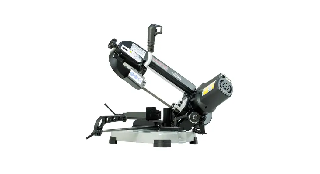
PORTABLE BAND SAW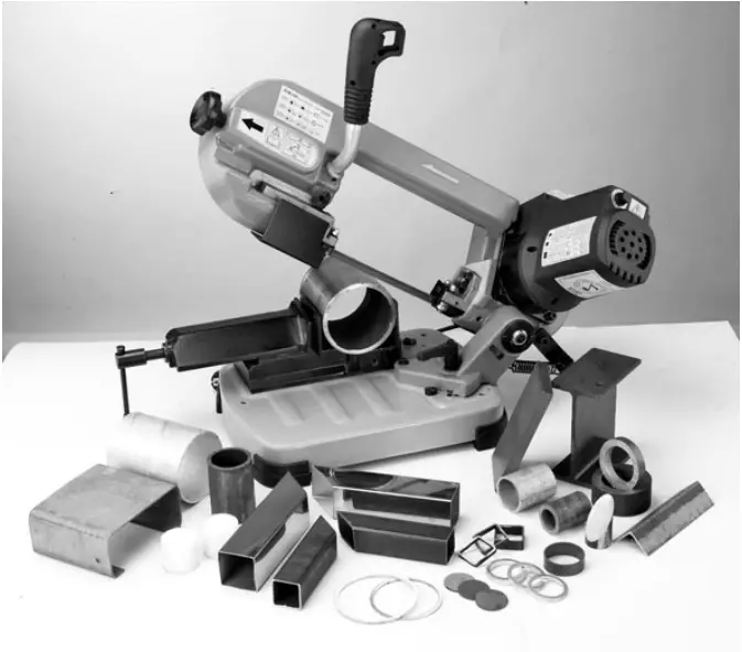
Portable band saw
SAFETY RULES
- KEEP GUARDS IN PLACE and in working order.
- REMOVE ADJUSTING KEYS AND WRENCHES. Form a habit of checking to see that keys and adjusting wrenches are removed from tool before turning it on.
- KEEP WORK AREA CLEAN. Cluttered areas and benches invite accidents.
- DON’T USE IN DANGEROUS ENVIRONMENT. Don’t use power tools in Damp or wet locations, or expose them to rain. Keep work area well lighted.
- KEEP CHILDREN AWAY. All visitors should be kept safe distance from work area.
- MAKE WORKSHOP KID PROOF with padlocks, master switches, or by removing starter keys.
- DO NOT FORCE TOOL. It will do the job better and safer at the rate for which it was designed.
- USE RIGHT TOOL. Do not force tool or attachment to do a job for which it was not designed.
- USE PROPER EXTENSION CORD. Make sure your extension cord is in good condition. When using an extension cord, be sure to use one heavy enough to carry the current your product will draw. An undersized cord will cause a drop in line voltage resulting in loss of power and overheating. Choose the correct size to use depending on cord length and nameplate ampere rating. If in doubt, use the next heavier gage. The smaller the gage number, the heavier the cord.
- WEAR PROPER APPAREL. Do not wear loose clothing, gloves, neckties, rings, bracelet or other jewelry, which may get caught in moving parts. Non-slip footwear is recommended. Wear protective hair covering to contain long hair.
- ALWAYS USE SAFETY GLASSES AND EAR PROTECTION. Also use face or dust mask if cutting operation is dusty. Everyday eyeglasses only have impact resistant lenses, they are NOT safety glasses.
- SECURE WORK. Use clamps or a vise to hold work when practical. It’s safer than using your hand and it frees both hands to operate tool.
- DO NOT OVERREACH. Keep proper footing and balance at all times.
- MAINTAIN TOOLS WITH CARE. Keep tools sharp and clean for best and safest performance. Follow instructions for lubricating and changing accessories.
- DISCONNECT TOOLS before servicing; when changing accessories, such as blades, bits, cutters, and the like.
- REDUCE THE RISK OF UNINTENTIONAL STARTING. Make sure switch is in off position before plugging in.
- USE RECOMMENDED ACCESSORIES. Consult the owner’s manual for recommended accessories. The use of improper accessories may cause risk of injury to persons.
- NEVER STAND ON TOOL Serious injury. Could occur if the tool is tipped or if the cutting tool is unintentionally contacted.
- CHECK DAMAGED PARTS. Before further use of the tool, a guard or other part that is damaged should be carefully checked to determine that it will operate properly and perform its intended function – check for alignment of moving parts, binding of moving parts, breakage of parts, mounting, and any other conditions that may affect its operation. A guard or other part that is damaged should be properly repaired or replaced.
- DIRECTION OF FEED. Feed work into a blade or cutter against the direction of rotation of the blade or cutter only.
- NEVER LEAVE TOOL RUNNING UNATTENDED. TURN POWER OFF. Don’t leave tool until it comes to a complete stop. To lock the main switch in the OFF position, remove the switch key from the switch.
Place the key in a location that is inaccessible to children and others not qualified to use the tool.
- WEAR EYE PROTECTION.
- DO NOT REMOVE CUT-OFF PIECES UNTIL BLADE HAS STOPPED.
- MAINTAIN PROPER ADJUSTMENT OF BLADE TENSION, BLADE GUIDES, AND TRUST BEARING.
- ADJUST UPPER GUIDE TO JUST CLEAR WORKPIECE.
- HOLD WORKPIECE FIRMLY AGAINST TABLE
Material to be cut
The tool is intended to cut matter material like steel. Iron, copper, etc. NEVER USE THIS TOOL TO CUT WOOD AND EXPLOSIVE METAL MATERIAL.
USE A CORRECT PLUG
As different countries may use different plug, so the user shall install the right plug approved in your country.
GROUNDING INSTRUCTIONS
In the event of a malfunction or breakdown, grounding provides a path of least resistance for electric current to reduce the risk of electric shock. This tool is equipped with an electric cord having an equipment-grounding conductor and a grounding plug. The plug must be plugged into a matching outlet that is properly installed and grounded in accordance with all local codes and ordinances.
Do not modify the plug provided – if it will not fit the outlet, have the proper outlet installed by a qualified electrician. Improper connection of the equipment-grounding conductor can result in risk of electric shock.
The conductor with insulation having an outer surface that is green with or without yellow stripes is the equipment-grounding conductor.
If repair or replacement of the electric cord or plug is necessary, do not connect the Equipment-grounding conductor to a live terminal. Check with a qualified electrician or service personnel if the grounding instructions are not completely understood, or if in doubt as to whether the tool is properly grounded.

Running in the blade
To safe guard the life and quality of a new blade, the first two or three cuts must be made exerting slight pressure on the piece so that the cutting time is almost twice the one normally needed (see cutting table).
Correct positioning of the piece in the clamp
Pieces to be cut must always be held firmly in the clamp, directly between the two jaws and without nserting other objects. For flat profiles, bars or particular shapes, refer to the examples in fig .B
To cut a long workpiece, use roll stand to support it.
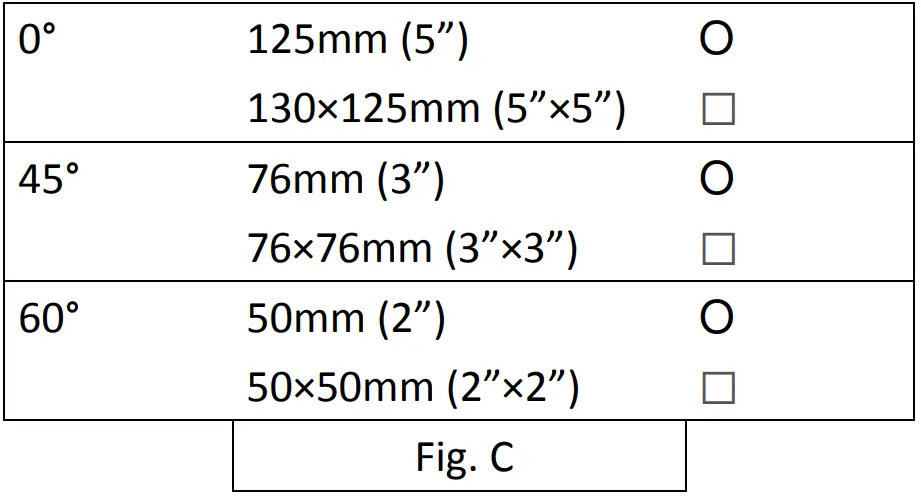
Choosing the blade Fig. C
Warning:
- NEVER USE BANDS WHICH ARE DAMAGED OR DEFORMED.
- NEVER CLEAN THE SAW BAND WHILST IT IS IN MOTION
The choice of the right blade and its toothing depends on the type of material you have to cut and on its section. Your band saw is fitted with a 1,440 x 13mm, 0.65mm thick metal blade, 10-14 tpi. Blades with 6-10 teeth per inch (EUROBOOR code 500.0001) are available as replacement.
Requirements, indicated in the “cutting table” (Fig. C).
Maintenance
- Be careful: before every cleaning or maintenance operation, ensure that the plug is not in the electric supply socket.
- Keep the cutting machine free from residue by means of a vacuum cleaner or a brush, passing it also over the blade guides. Keep the band saw in good condition: if it is not to be used for a long time, put it away in its original packing in a damp-free place. In these cases it is advisable to slacken the blade so as not to keep it under tension unnecessarily.
| Item. | Specifications. | Item. | Specifications. |
| Voltage | 110-120V or 220-240V | Blade size | 13 x 0.65 x 1,440mm |
| Frequency | 50-60Hz | Dimensions | 650 x 310 x 450mm (machine) 724 X 375 x 460mm (packaging) |
| Motor | 1,010W (single phase) | ||
| Cutting speed | adjustable, 30-80m (100-265ft) per minute | Noise level | About 60 dB (A) |
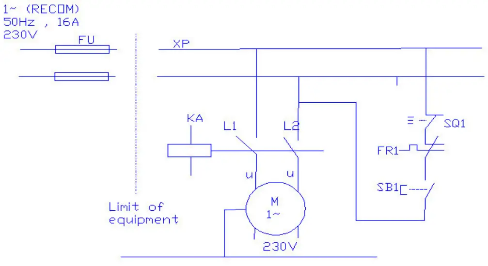
ELECTRICAL PART LIST
| Item | Description | Description and function | Technical data |
| 1 | SB1 | TR26-21C-13D/L SM-84P Switch with light | IP54:250Vac CE |
| 2 | Supply Cable | Ac 600V, 10A 3G/0.75 mm | |
| 3 | M | Motor | 1,010W/230V,IP54 |
| 4 | SQ1 | ZIPPY Micro Switch,VMN-15,15A | 20.5A 125/250 Vac CE |
| 5 | FR1 | Over Load | 3.7A / 250 Vac CE |
CIRCUIT DIAGRAM
OPERATION AND ASSEMBLY INSTRUCTIONS
Fig. 1
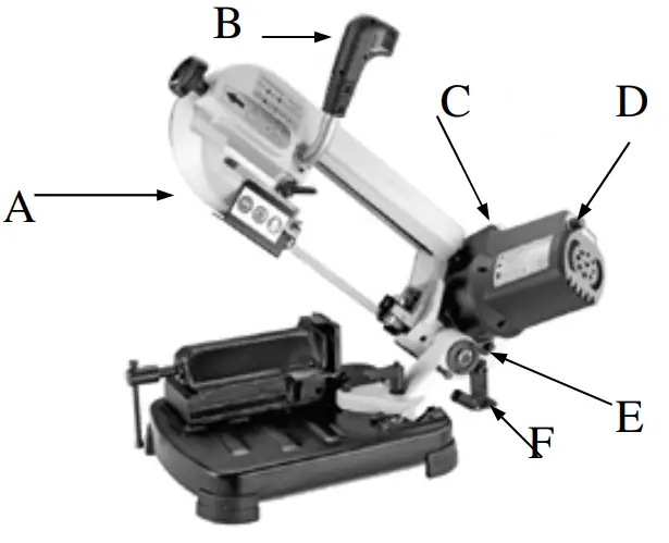
This view shows the:
| Machine body | (A) | Handle | (B) |
| Switch | (C) | Knob | (D) |
| Rod | (E) | Locking Handle | (F) |
MANUAL CUTTING
For the spring ! Tighten the screw (E) to position the steel plate (F) at around 45 degrees.
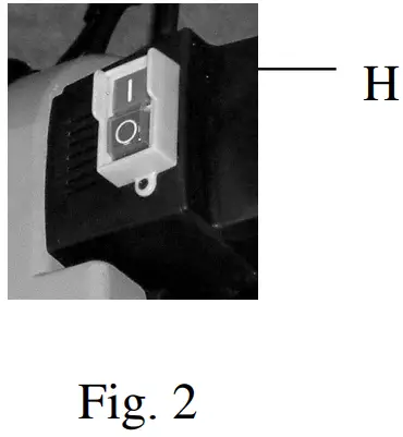
Fig. 2
To start the machine press switch (H of Fig. 2) to ON (I).
Use the handle (B of Fig. 1) for manual cutting.
This machine is designed for cutting without cooling.
Heat in the saw blade will build up. Do not operate the machine continuously for more than 70min.
!WARNING:
WHEN THE TOOL IS NOT IN USE THE SWITCH SHOULD BE LOCKED IN THE OFF (O) POSTION.
ADJUSTMENTS
Adjusting the distance set Bracket
If you have to cut several pieces all of the same length, use the set bracket (D of Fig. 1) provided with the band saw.
Fig. 3 Adjusting the blade guide
Your cutting machine is provided with a sliding guide (I of Fig. 3) with built-in protection, which guides the part of the blade necessary to make the cut, and at the same time, protects the part of the blade not in use. To do this, simply slacken the locking handle (J of Fig. 3) and slide the blade guide (I of Fig. 3) so as to bring it closer to or farther from the piece that is to be cut.
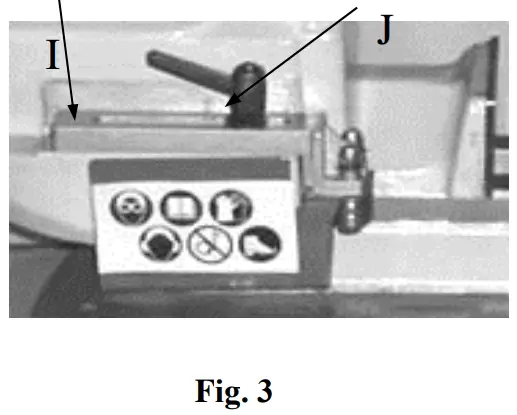
Fig. 4 Adjusting the cutting angle
The band saw can cut an angle varying from 0° to 60°. Slacken the locking handle (K of Fig. 4) and turn the saw (L of Fig. 4) until the scale to the desired angle. Then tighten the locking handle.
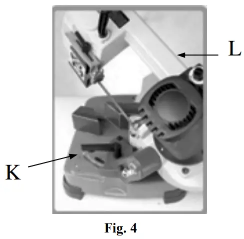
Fig. 5 Blade replacement
Raise saw head to vertical position and open the blade guards.
Loosen tension screw knob (A of Fig. 5) sufficiently to allow the saw blade to slip off the wheels. Install the new blade with teeth slanting toward the motor as follows:
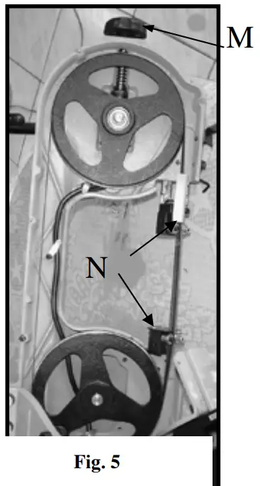
- Place the blade in between each of the guide bearings (N of Fig. 5).
- Slip the blade around the motor pulley (bottom) with the left hand and hold in position.
- Hold the blade taut against the motor pulley by pulling the blade upward with the right hand, which is placed, at the top of the blade.
- Remove left hand from bottom pulley and place is at the top aide of the blade to continue the application on the upward pull on the blade.
- Remove right hand from blade and adjust the position of the top pulley to permit left hand to slip the blade around the pulley using the thumb. Index and little finger as guides.
- Adjust the blade tension knob (M of Fig. 5) clockwise until it is just right enough so no blade slippage occurs. Do not tighten excessively.
- Replace the blade guards.
- Place 1-2 drops of oil on the blade.
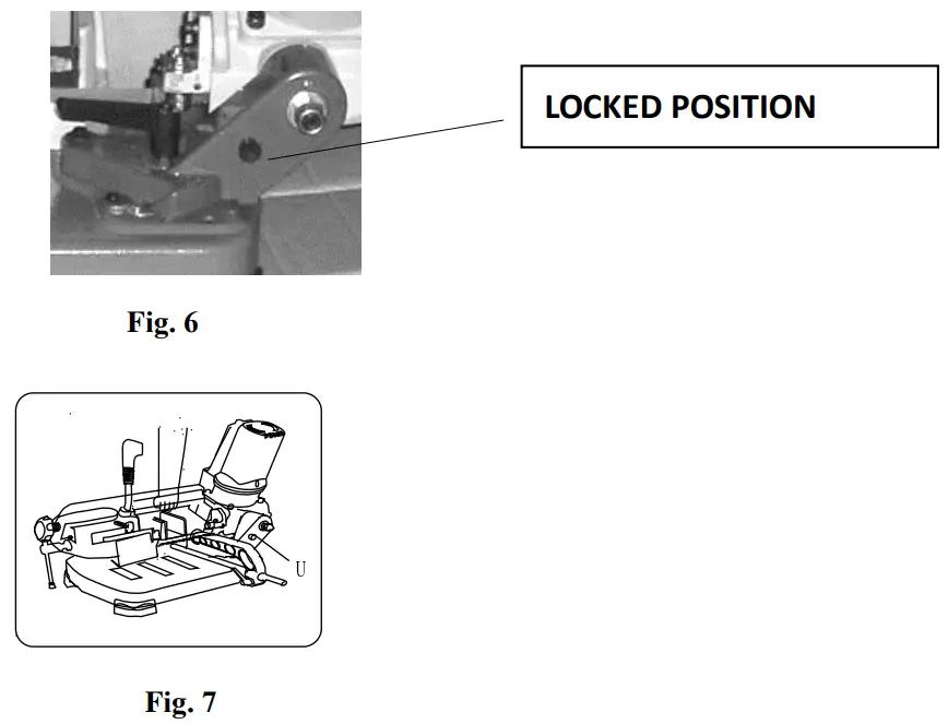
Transportation
Before transporting the tool, be sure to lock the upper
And lower side as shown in Fig. 6.
Then lift the tool as shown in Fig. 7.
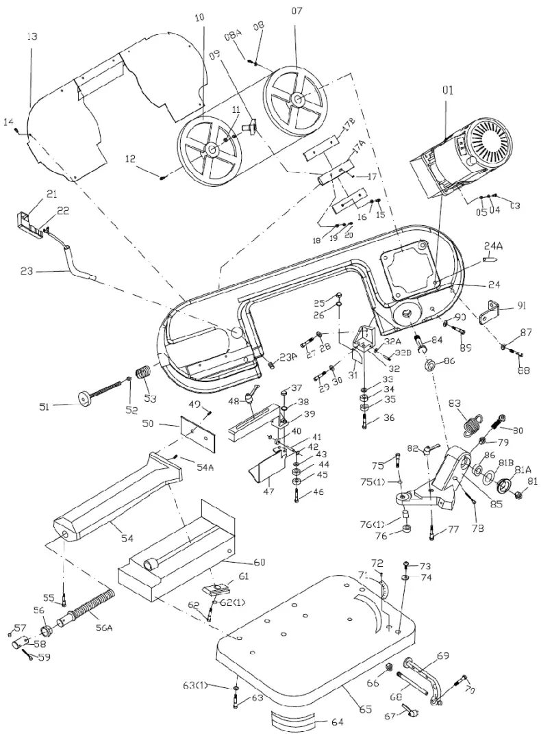
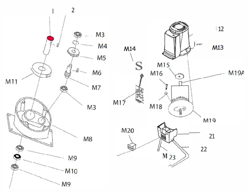
SPARE PARTS LIST
| No. | Qty used | Art.nr. | Description | No. | Qty used | Art.nr. | Description |
| 1 | 1 | 500.0002 220v | Complete Motor with Gear | 56-59 | 1 | 500.0056 | Acme screw set |
| 1 | 1 | 500.0002 110v | Complete Motor with Gear | 60 | 1 | 500.006 | Fence base |
| 3 | 4 | 500.0003 | Screw Cap 8*25 | 61 | 1 | 500.0061 | Locking Seat |
| 4 | 4 | 500.0004 | Spring Washer M8 | 62 | 1 | not available | not available |
| 5 | 4 | not available | not available | 62(1) | 1 | not available | not available |
| 7 | 1 | 500.0007 | Motor Fly wheel | 63 | 6 | 500.0063 | Screw Cap 8*16 |
| 8 | 1 | not available | not available | 63(1) | 1 | not available | not available |
| 8A | 1 | not available | not available | 64 | 4 | 500.0064 | Rubber Pad |
| 9 | 1 | 500.0009 | Dog Pin | 65 | 1 | not available | not available |
| 10 | 1 | 500.001 | Return Fly wheel | 66 | 1 | not available | not available |
| 11 | 2 | 500.0011 | Bearing 6202 | 67 | 1 | not available | not available |
| 12 | 1 | 500.0012 | Screw Cap 8*16 | 68 | 1 | 500.0068 | Rod stock stop |
| 13 | 1 | 500.0013 | Body cover | 69 | 1 | 500.0069 | Stop Bracket |
| 14 | 4 | not available | not available | 70 | 1 | not available | not available |
| 15 | 4 | not available | not available | 71 | 1 | not available | not available |
| 16 | 4 | not available | not available | 72 | 1 | not available | not available |
| 17 | 1 | 5,000,017 | Set screw 8*16 | 73 | 2 | not available | not available |
| 17A | 1 | 500.0017A | Blade tension sliding block | 74 | 2 | not available | not available |
| 17B | 2 | 500.0017B | Slide | 75 | 1 | not available | not available |
| 18 | 4 | not available | not available | 75(1) | 1 | not available | not available |
| 19 | 4 | not available | not available | 76 | 1 | 500.0076(1) | Bushing |
| 20 | 4 | 500.002 | Screw cap 8*25 | 76(1) | 1 | not available | not available |
| 21 | 1 | 500.0021 | Limit switch | 77 | 1 | not available | not available |
| 22 | 1 | 500.0022 | Handle | 78 | 1 | not available | not available |
| 23 | 1 | 500.0023 | Tube | 79 | 1 | not available | not available |
| 23A | 1 | not available | not available | 80 | 1 | 500.008 | Spring holder |
| 24 | 1 | 500.0024 | Body Frame | 81 | 1 | 500.0081 | Bearing Nut |
| 24A | 1 | 500.0024A | Blade | 81A | 1 | 500.0081A | Bushing |
| 25 | 2 | not available | not available | 81B | 1 | 500.0081B | Bearing cover |
| 26 | 2 | not available | not available | 82 | 1 | 500.0082 | Bolt |
| 27 | 2 | 500.0027 | Screw cap6*25 | 83 | 1 | 500.0083 | Spring |
| 28 | 2 | not available | not available | 84 | 1 | 500.0084 | Axis |
| 29 | 1 | 500.0029 | Screw cap 5*10 | 85 | 1 | 500.0085 | Miter plate |
| 30 | 1 | not available | not available | 86 | 2 | 500.0086 | Bearing |
| 31 | 1 | 500.0031 | Chip fence | 87 | 1 | not available | not available |
| 32 | 1 | 500.0032 | Fixed blade guide plate | 88 | 1 | not available | not available |
| 32A | 1 | 500.0032A | Bearing 625 | 89 | 1 | not available | not available |
| 32B | 1 | 500.0032B | Pin | 90 | 1 | not available | not available |
| 33 | 2 | not available | not available | 91 | 1 | 500.0091 | Screws |
| 34 | 2 | 500.0034 | Bearing 607 | M1 | 1 | 500.1001 | Main shaft |
| 35 | 2 | 500.0035 | Bearing 607 | M2 | 1 | 500.1002 | Key |
| 36 | 2 | 500.0036 | Bias axis | M3 | 2 | 500.1003 | Bearing |
| 37 | 2 | not available | not available | M4 | 1 | 500.1004 | C-ring |
| 38 | 2 | not available | not available | M5 | 1 | 500.1005 | Gear |
| 39 | 1 | 500.0039 | Arm | M6 | 1 | 500.1006 | key |
| 40 | 2 | 500.004 | Bearing 625 | M7 | 1 | 500.1007 | Gear shaft |
| 41 | 2 | 500.0041 | Pin | M8 | 1 | 500.1008 | Gear Box |
| 42 | 2 | not available | not available | M9 | 2 | 500.1009 | Bearing |
| 43 | 2 | not available | not available | M10 | 1 | 500.101 | oil seal |
| 44 | 2 | 500.0044 | Bearing 607 | M11 | 1 | 500.1011 | Gear |
| 45 | 2 | not available | not available | M12 | 1 | 500.1012 | Up cover |
| 46 | 2 | not available | not available | M13 | 1 | 500.1013 | Screws |
| 47 | 1 | 500.0047 | L.Blade guard | M14 | 1 | 500.1014 | Nut |
| 48 | 1 | 500.0048 | Bolt | M15 | 1 | 500.1015 | Fan |
| 49 | 1 | not available | not available | M16 | 1 | 500.1016 | screw |
| 50 | 1 | 500.005 | Vice Plate | M17 | 1 | 500.1017 | Electric board |
| 51 | 1 | 500.0051 | Handle wheel | M18 | 1 | 500.1018 | oil seal |
| 52 | 1 | not available | not available | M19 | 1 | 500.1019 | Motor |
| 53 | 8 | not available | not available | M20 | 1 | 500.102 | Switch |
| 54 | 1 | 500.0054 | Vice | M21 | 1 | 500.1021 | Down cover |
| 54A | 1 | not available | not available | M22 | 1 | 500.1022 | plug |
| 55 | 1 | not available | not available | M23 | 1 | 500.1023 | Handle wire |


