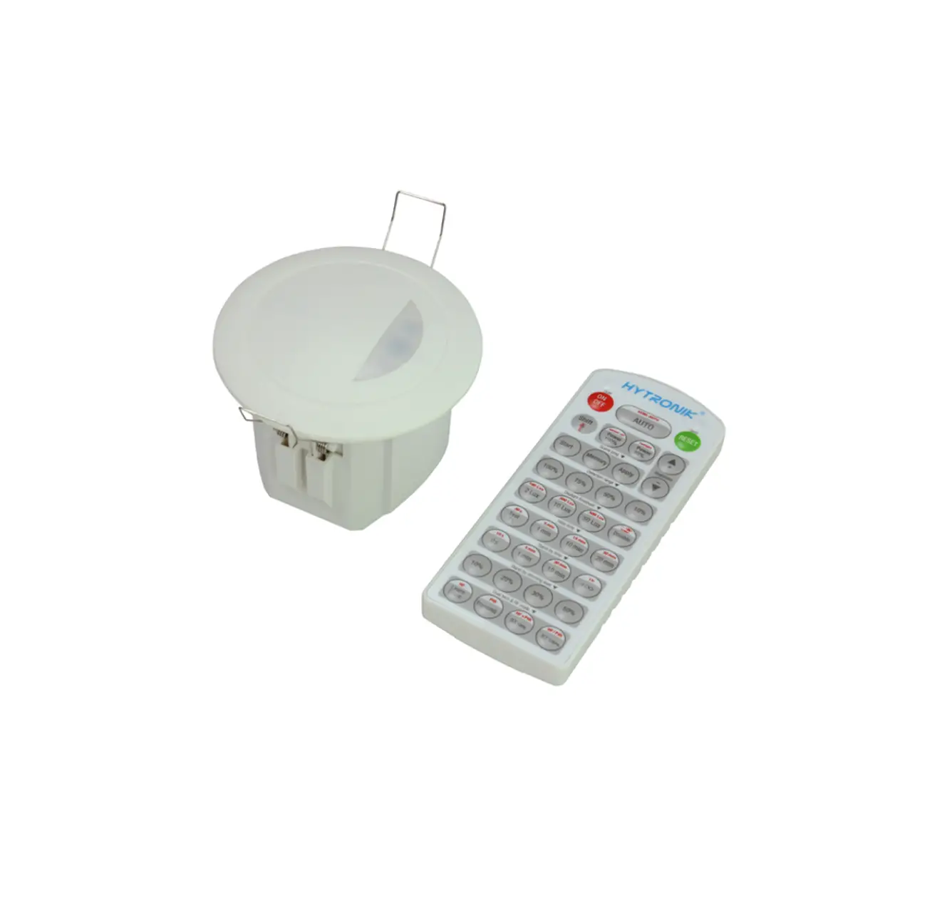
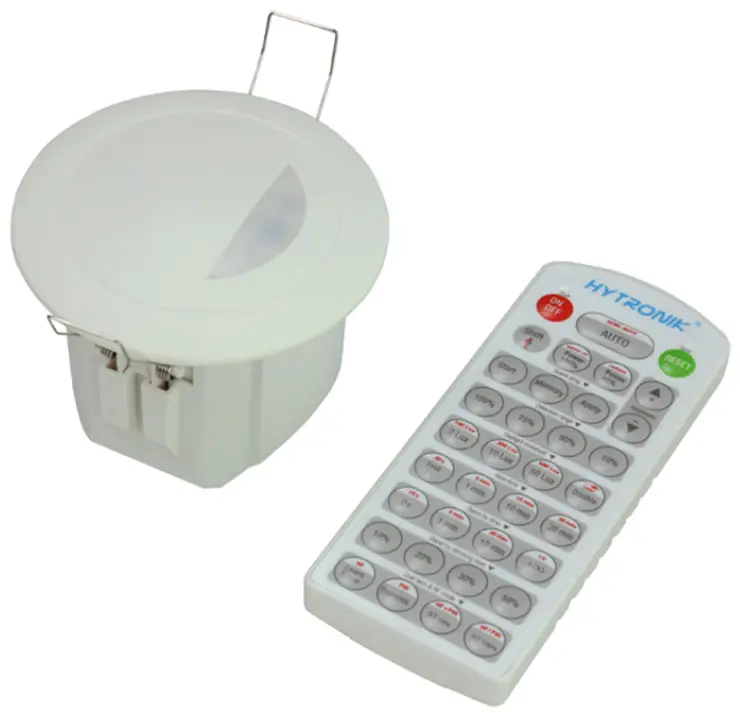
HYTRONIK HMW20 Flush Mount Microwave Motion Sensor
Technical Specifications
| Product type | On/off control microwave motion sensor |
| Operating voltage | 220-240VAC 50/60Hz |
| Rated load | 1200W (resistive); 400VA (capacitive) |
| Power consumption | < 1W |
| Detection angle | 360o |
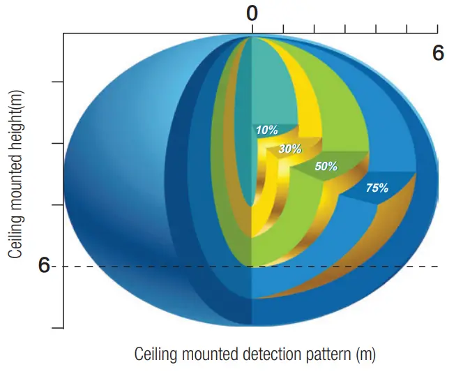
| Detection area (Max.)* | Installation Height : 6m Detection Range (Ø) :12m |
| Detection range | 10% / 50% / 75% / 100% |
| Hold time | 2s / 30s / 1min / 5min / 10min / 15min / 20min / 30min |
| Daylight threshold | 2 ~ 500Lux, Disable |
| Warmming up time | 20s |
| Operating temperature | -20oC ~ +50oC |
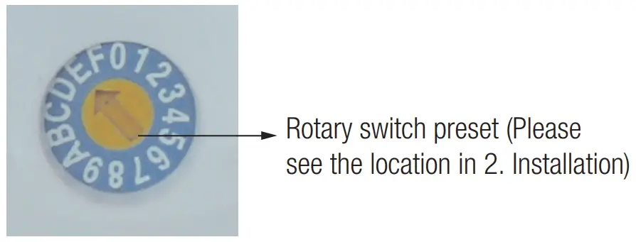
Rotary Switch Settings
A rotary switch is built inside the sensor for scene selection / fast programming. Total 16 channels are available:
| Channel | Detection range | Hold time | Daylight threshold |
| 0 | 100% | 5s | Disable |
| 1 | 100% | 30S | 2Lux |
| 2 | 100% | 1min | 10Lux |
| 3 | 100% | 5min | 2Lux |
| 4 | 100% | 5min | 10Lux |
| 5 | 100% | 5min | 30Lux |
| 6 | 100% | 5min | 50Lux |
| 7 | 100% | 5min | Disable |
| 8 | 100% | 10min | 10Lux |
| 9 | 100% | 10min | 30Lux |
| A | 100% | 10min | 50Lux |
| B | 75% | 10min | 30Lux |
| C | 50% | 10min | 10Lux |
| D | 100% | 30min | 10Lux |
| E | 100% | 30min | 50Lux |
| F | 100% | 5s | 2Lux |
Note: settings can also be changed by remote control HRC-11. The last action controls.
Functions
On/off Control
This sensor is a motion switch, which turns on the light on detection of people movement, and turns off after a pre-selected hold-time when there is no people around. A daylight sensor is also built-in to prevent the light switching on when there is sufficient natural light.
Zero-cross relay operation
Designed in the software, sensor switches on/off the load right at the zero-cross point, to ensure the in-rush current is minimized, enabling the maximum lifetime of the relay.
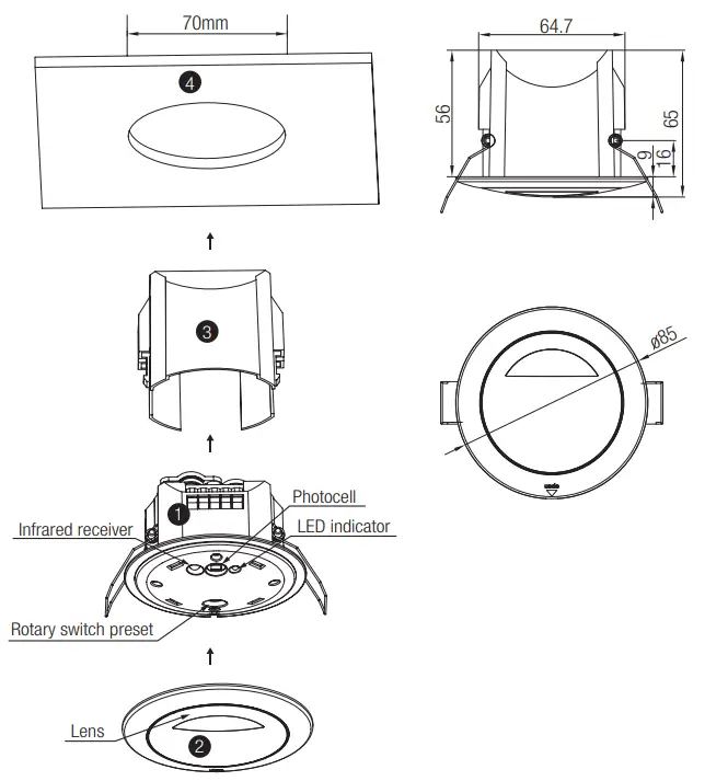
Installation
 Warnings:
- Installation of the sensor involves connecting it to the mains supply. This work must be carried out by a specialist in accordance with electrotechnical regulations.
- Disconnect power supply before installing.

|
Note: We recommend the mounting distance between sensor to sensor should be more than 2m to prevent sensors from false-triggering.
Semi-auto Function (Absence Detection)
The motion sensor is employed, but only activated on the manual press of the push switch, light remains keeps on in the presence, switches off automatically in the long absence.
Note: this function can be chosen by remote controller only, please refer to detailed explanations in part 7.
Manual Override / Push Function (Default)
With the help of push-switch, this sensor maybe over-ridden by the end-users to switch on/off the lights manually. This makes the product more user-friendly and offers more options to fit for extra ordinary demands.
* Push: on/off function;
ON → OFF: the light turns off immediately and cannot be lightened for a certain time (equals to hold time preset) even movement is detected. After this period, the sensor goes back to auto sensor mode.
OFF → ON: the light turns on and goes to auto sensor mode.
Detection Pattern
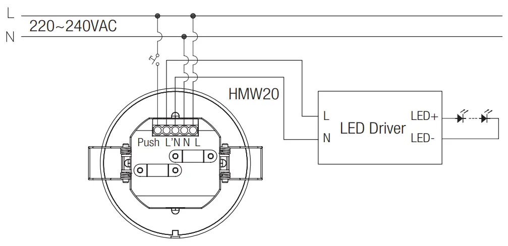
Wiring Diagram
Permanent ON/OFF [ button ① ]
Press button ① to select permanent ON or permanent OFF mode.
* Press button ② / ④ to resume automatic operation.
The mode will change to AUTO Mode after power failure.
RESET [ button ② ]
Press button ② , all settings go back to the rotary switch settings.
Shift [ button ③ ]
Press button ③ , the LED on the top left corner is on for indication. All values / settings in RED are valid for 20 seconds.
Auto Mode [ button ④ ]
Press button ④ to initiate automatic mode. The sensor starts working and all settings remain as before the light was switched ON/OFF.
Semi-auto Mode [ button ③ & ④ ]
- Press button Shift (the red LED is on for indication),
- press button to initiate semi-auto mode. The fixture is manually on by push-switch and automatically off in semi-auto mode.
Power output [ button ⑤ ]
All buttons in zone ⑤ are disabled.
Brightness +/- [ button ⑥ ]
All buttons in zone ⑥ are disabled.
Scene prog. [ zone ⑦ ] (One-key-commissioning)
- Press button “Start” to program.
- Select the buttons in ⑧ “Detection range”, ⑨/ ⑩ “Daylight threshold”, “Hold time” to set all parameters.
- Press button “Memory” to save all the settings programmed in the remote control.
- Press button “Apply” to set the settings to each sensor unit(s). For example, to pre-set detection range 100%, daylight threshold Disable, hold time 5min, the steps should be as follows:
Press button ⑦ Start, button ⑧ 100%, ⑩ Disable, ③ Shift, 5min, ⑦ Memory. By pointing to the sensor unit(s) and pressing ⑦ Apply, all settings are passed on the sensor(s).
Detection range [ zone ⑧ ]
Press buttons in zone ⑧ to set detection range at 100% / 75% / 50% / 10%.
Daylight threshold [ zone ]
Press buttons in zone ⑨ to set the daylight sensor at 2Lux / 10Lux / 50Lux / 100Lux / 300Lux / 500Lux or Disable.
Note: To set daylight sensor at 100Lux / 300 Lux / 500Lux, press button ③ Shift at first.
Ambient daylight threshold [ button ]
- Press button Shift, the red LED is on for indication.
- Press button ⑩ , the ambient lux level is sampled and set as the new daylight threshold.
Hold time [ zone ⑪ ]
Press buttons in zone ⑩ to set the hold time at 2s / 30s / 1min / 5min / 10min / 15min / 20min / 30min
Note:
- To set hold-time at 30s / 5min / 15min / 30min, press button Shift at first.
- 2s is for testing purpose only, stand-by period and daylight sensor settings are disabled in this mode
*To exit from Test mode, press button ② or any button in zone ⑪ .
Note: all buttons in zone ⑫ are disabled.
Troubleshooting
| MALFUNCTION CAUSE REMEDY | CAUSE | REMEDY |
| The fixture does not light up | Incorrect daylight threshold setting | Adjust daylight threshold setting |
| Faulty fixture | Replace fixture | |
| No power supply | Check power to sensor | |
| Detection zone not targeted | Check detection area setting | |
| The fixture is always on | Continous movement in the detection zone | Check detection area setting |
| The fixture is on when it should not | Sudden change in temperature due to weather (wind, rain, snow) or air expelled from fans, open windows | Adjust zone, change installation site |
Customer Support
Hytronik Industrial Ltd. | www.hytronik.com
3rd Floor, block C, complex building, 155#, Bai’gang road south,
Bai’gang village, Xiao Jin Kou town, Huicheng district, Huizhou 516023
Tel: 86-752-2772020 Fax: 86-752-2777877