![]()
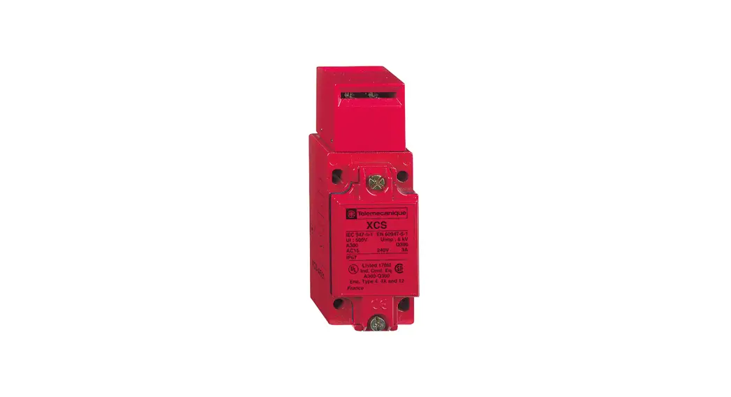
XCSA-B-C Safety Interlock Switch
Instruction Manual
XCSA/B/C
Safety interlock switch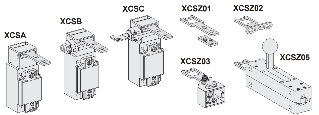
XCSA-B-C Safety Interlock Switch
These devices have been designed to be in compliance with the standards currently in effect: EN/IEC 60947-5-1, EN/ISO 13849-1, EN/IEC 62061, EN/IEC 60947-1, EN/ISO 14119, EN/IEC 60204. These devices can achieve up to category 4 PL=e or SIL 3 (if combined with an appropriate Control Safety Unit PL=e / SIL 3).
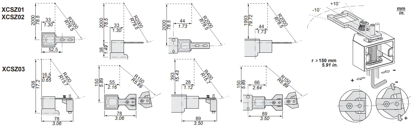
Dimensions
1/2’’ NPT : in case of connection by a metal conduit, a flexible metal conduit shall be used. Max. conduit torque : 9 NM / 80 Lb.in
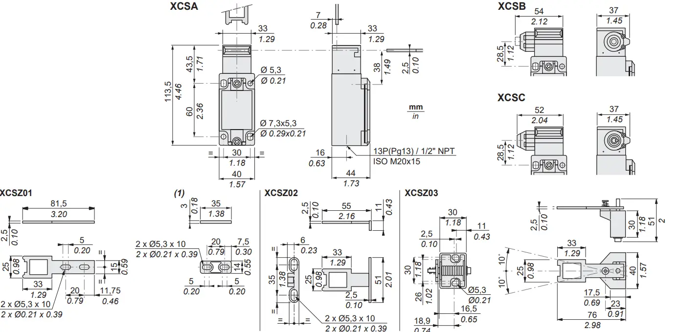
(1) Shim provided with XCSZ01 enabling an XCK-J with a ZCKY07 key to be replaced by an XCS-A/B/C with an XCSZ01 key without predrilling any attaching holes.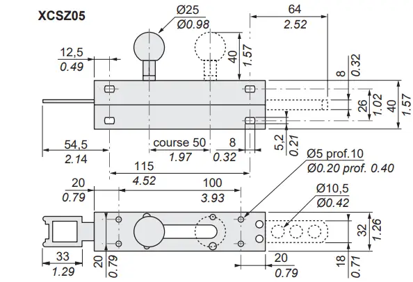
Electrical equipment should be installed, operated, serviced, and maintained only by qualified personnel. No responsibility is assumed by Schneider Electric for any consequences arising out of the use of this material.
Tongued key actuation radii
Head orientation
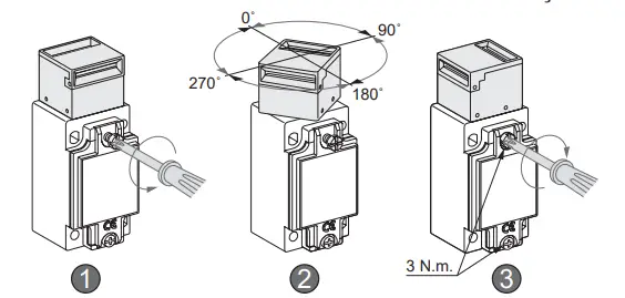
Tightening torque, tightening capacity
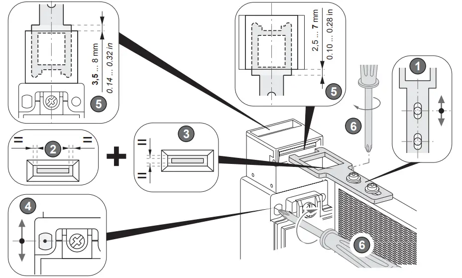
Adjustment of tongued keys
The safety interlock switch must not be used as a mechanical stop or as a centering tool for the moving guard. An additional limit stop on the fixed part must be anticipated. After adjustment, make it impossible to dismantle the support key.![]() Only keys XCSZ 01/02/03/05 must be used.
Only keys XCSZ 01/02/03/05 must be used.
Contact status
– Contact closed (1)
– Contact open (0)
– Transient state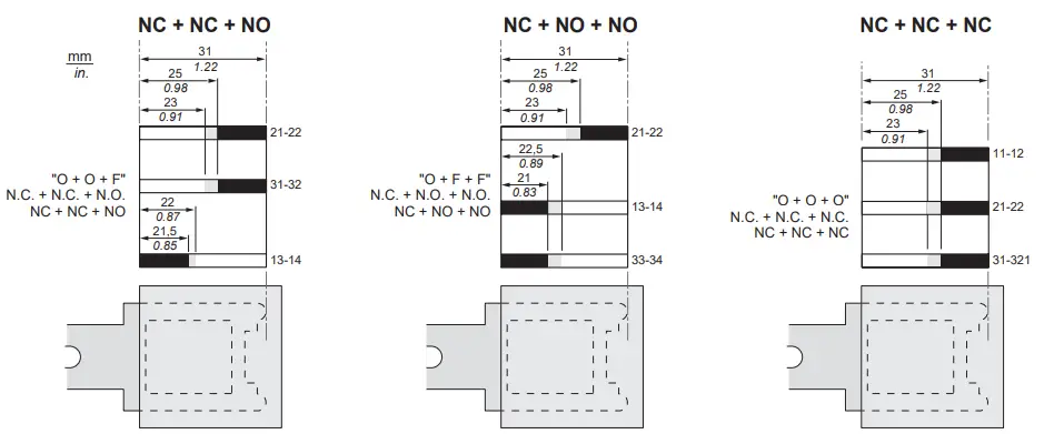
Position of keylock on XCS-B/C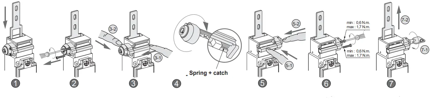
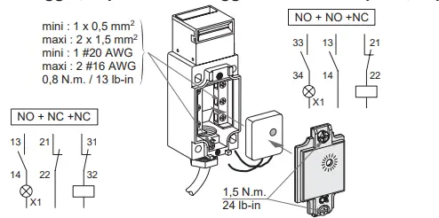
Wiring diagram
Cat. 1 – PL=c (EN/ISO 13849-1)
XCSA5••
XCSB5••
XCSC5••
NC + NO + NO
Check that starting cannot be carried out when the protector is opened.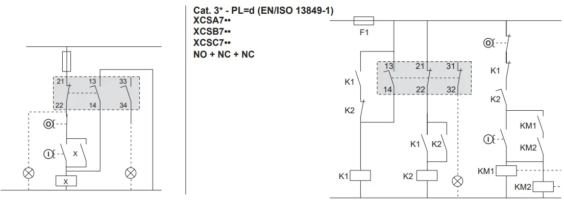 * For mechanical/electrical redundancy, add another switch with positive opening contacts
Maintenance:
It is imperative to check the following points regularly
– the mechanical adjustment of product XCS/A/B/C with the XCSZ01/02/03/05 tongued key
– wear: the devices should not be used beyond the characteristics stated in catalogues
– make sure of t he good electric switching
– it is forbidden to modify the devices.
Any and all liability shall be excluded in case of non compliance with the requirements of this notice
![]() DANGER
DANGER
HAZARD OF ELECTRIC SHOCK, BURN OR EXPLOSION
Turn off all power before working on this equipment.
Failure to follow these instructions will result in death or serious injury.
| Characteristics | UL, CSA, CCC, EAC |
| Product certifications | Operation : -25…+70 C° / -13…158 F°………..Storage : -40…+70 C° / -40…158 F° |
| Ambient air temperature | 5 gn (10-500 Hz) conforming to EN/IEC 60068-2-6 |
| Vibration resistance | 10 gn (11 ms) conforming to EN/IEC 60068-2-27 |
| Shock resistance | – XCSB/C: 0,6 x 10 XCSA: 10 |
| Number of operations | – XCSB/C: 0,6 x 10 |
| Reliability data B10d | XCSA: 5.000.000 – XCSB/C: 3.000.000 (data value for a service life of 20 years can be limited by contact and mechanical wear) |
| Rated electric characteristics of use | a AC-15, A300 : Use = 240 V, Ie = 3 A or Ue = 120 V, Ie = 6 A c DC-13, Q300: Ue = 250 V, Ie = 0,27 A or Use = 125 V, Ie = 0,55 A conforming to IEC 60 947-5-1, EN 60 947-5-1 |
| Protection against electric shock | Class I conforming to EN/IEC 61140 |
| Actuation speed | mini = 0,01 m/s (0.39 in/s) – maxi = 0,5 m/s (19.68 in/s) |
| Short-circuit protection | 10 A gG (gl) cartridge fuse (use type CC in the United States) |
| Cable connection | Screw clamps terminals…………………… Clamping capacity : min : 1 #20 AWG (1 x 0.5 mm |
| Minimum key pull-out resistance | 2 |
| Resistance to forcible withdrawal of actuator | ) , max : 2 #16 AWG (2 x 1.5 mm |
Уполномоченный поставщик в РФ :
АО «Шнейдер Электрик»
Адрес: 127018, Россия, г. Москва, ул. Двинцев, д.12, корп.1
Тел. +7 (495) 777 99 90
Факс +7 (495) 777 99 92
www.tesensors.com


