![]()
INSTALLER’S GUIDE
ALL phases of this installation must comply with NATIONAL, STATE AND LOCAL CODES
Model: BAYSENSC360
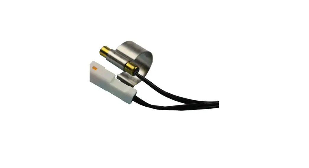
BAYSENSC360 Supply Duct Air Temperature Sensor
Supply Duct Air Temperature Sensor
Used with Link Air Handlers and Furnaces (included with TSYS2C60A2VVU* System Controller) Link Communicating or 24V modes.
IMPORTANT – This Document is customer property and is to remain with this unit. Please return to service information pack upon completion of work.
Safety Considerations
![]() WARNING THE INFORMATION IN THIS GUIDE IS FOR USE BY INDIVIDUALS HAVING ADEQUATE ELECTRICAL AND MECHANICAL BACKGROUND. ANY ATTEMPTS, BY UNQUALIFIED PERSONS, AT PLUMBING, INSTALLING OR REPAIRING A HYDRONIC SYSTEM OR CENTRAL AIR CONDITIONING PRODUCT COULD RESULT IN PROPERTY DAMAGE, SEVERE PERSONAL INJURY OR DEATH. THE MANUFACTURER OR SELLER CANNOT BE RESPONSIBLE FOR THE INTERPRETATION OF THIS INFORMATION, NOR CAN IT ASSUME ANY LIABILITY IN CONNECTION WITH ITS USE.
WARNING THE INFORMATION IN THIS GUIDE IS FOR USE BY INDIVIDUALS HAVING ADEQUATE ELECTRICAL AND MECHANICAL BACKGROUND. ANY ATTEMPTS, BY UNQUALIFIED PERSONS, AT PLUMBING, INSTALLING OR REPAIRING A HYDRONIC SYSTEM OR CENTRAL AIR CONDITIONING PRODUCT COULD RESULT IN PROPERTY DAMAGE, SEVERE PERSONAL INJURY OR DEATH. THE MANUFACTURER OR SELLER CANNOT BE RESPONSIBLE FOR THE INTERPRETATION OF THIS INFORMATION, NOR CAN IT ASSUME ANY LIABILITY IN CONNECTION WITH ITS USE.![]() WARNING ELECTRICAL HAZARD!
WARNING ELECTRICAL HAZARD!
DISCONNECT ALL ELECTRICAL POWER, INCLUDING REMOTE DISCONNECTS BEFORE INSTALLING OR SERVICING. FOLLOW PROPER LOCKOUT/TAGOUT PROCEDURES TO ENSURE THE POWER CAN NOT BE INADVERTENTLY ENERGIZED. FAILURE TO FOLLOW THIS WARNING COULD RESULT IN SERIOUS PERSONAL INJURY, DEATH, OR PROPERTY DAMAGE.
Inspection
- Unpack all components of the kit.
- Check carefully for any shipping damage. If any damage is found, this must be reported immediately and a claim made against the transportation company.
- Check to be sure all components are in the package. Any missing components should be reported to your supplier at once and replaced with authorized components only.
General Information
The supply duct air temperature sensor can only be seen using the mobile diagnostics app.
Specifications
Operating Temperature Range: -40°F – 150°F (-40°C – 65°C)
Sensor Accuracy
± 2%
Dimensions
Probe – 6.5” x 0.25” (16.5cm x 0.635cm)
Harness – 96” (243.8cm)
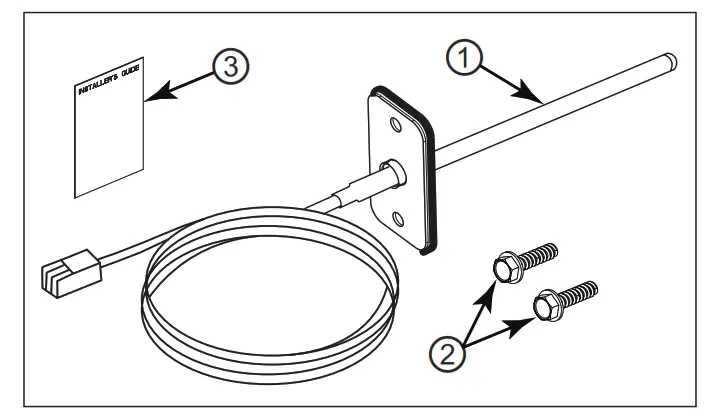
Kit Contents
Each kit will contain:
| Item | Qty | Description |
| 1 | 1 | Supply Duct Air Temperature Sensor |
| 2 | 2 | #10 x 16 Hex Screws |
| 3 | 1 | Installer’s Guide |
INSTALLER’S GUIDE
Installation
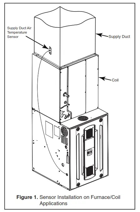
Furnace / Coil Applications
NOTE: For heating only applications, locate the sensor as far from the furnace as the sensor harness length will allow.
- The recommended location of the sensor is on the left side of the duct above the cooling coil.
- If the left side is not available, it is recommended to take several temperature readings to find the best “average” location to mount the sensor.
- Drill a 5/16” hole in the supply duct and insert the sensor and secure with the supplied screws. See Figure 1.
- Plug the sensor into the IFC connector, E22 (SUP_T).
- Power on the unit and enable “Supply Air Sensor” using the mobile diagnostics app.
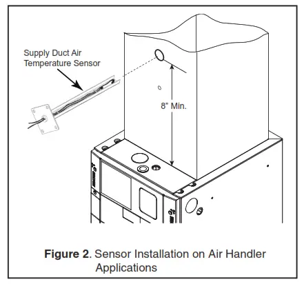
Air Handler Applications
- The recommended location of the sensor is on the front of the supply duct, with a minimum distance of 8” above the top of the air handler. See Figure 2. Additional distance is preferred and will yield a more accurate temperature.
- If the front side is not available, it is recommended to take several temperature readings to find the best “average” location to mount the sensor.
- Drill a 5/16” hole in the supply duct and insert the sensor and secure with the supplied screws.
- Plug the sensor into the AHC connector, J11 (SUP_T).
- Power on the unit and the air handler control board will auto-detect and enable the sensor.
Resistance and Voltage Table
| Tdeg F | TdegC | THERMISTOR RESISTANCE | VDC VDC |
| 40 | 4. | 25452 | 2. |
| 41 | 5.0 | 24761 | 2. |
| 42 | 6. | 24090 | 1.60 |
| 43 | 6. | 23440 | 2. |
| 44 | 7. | 22810 | 2. |
| 45 | 7. | 22198 | 2. |
| 46 | 8. | 21605 | 2. |
| 47 | 8. | 21030 | 2. |
| 48 | 9. | 20472 | 1. |
| 49 | 9. | 19931 | 147 |
| 50 | 10.0 | 19405 | 1. |
| 51 | 11. | 18896 | 1. |
| 52 | 11. | 18401 | 1. |
| 53 | 12. | 17921 | 1. |
| 54 | 12. | 17455 | 1. |
| 55 | 13. | 17002 | 1. |
| 56 | 13. | 16563 | 1. |
| 57 | 14. | 16137 | 1. |
| 58 | 14. | 15723 | 1. |
| 59 | 15.0 | 15320 | 1. |
| 60 | 16. | 14930 | 125 |
| 61 | 16. | 14550 | 1. |
| 62 | 17. | 14182 | 1. |
| 63 | 17. | 13824 | 1. |
| 64 | 18. | 13476 | 1. |
| 65 | 18. | 13138 | 1. |
| 66 | 19. | 12810 | 1. |
| 67 | 19. | 12491 | 1. |
| 68 | 20.0 | 12181 | 1. |
| 69 | 206 | 11879 | 1. |
| 70 | 21. | 11586 | 1. |
| 71 | 217 | 11301 | 1. |
| 72 | 22. | 11024 | 1. |
| 73 | 23. | 10754 | 1.00 |
| 74 | 23. | 10492 | 0.98 |
| 75 | 24. | 10238 | 0.96 |
| 76 | 24. | 9990 | 0.95 |
| 77 | 25.0 | 9749 | 0.93 |
| 78 | 26. | 9515 | 0.91 |
| 79 | 26. | 9287 | 0.89 |
| 80 | 27. | 9065 | 0.88 |
| 81 | 27. | 8849 | 0.86 |
| 82 | 28. | 8639 | 0.84 |
| 83 | 28. | 8435 | 0.83 |
| 84 | 29. | 8236 | 0.81 |
| 85 | 29. | 8043 | 0.80 |
| 86 | 30.0 | 7855 | 0.78 |
| 87 | 31. | 7671 | 0.77 |
| 88 | 31. | 7493 | 0.75 |
| 89 | 32. | 7319 | 0.74 |
| 90 | 32. | 7150 | 0.72 |
| 91 | 33. | 6985 | 0.71 |
| 92 | 33. | 6825 | 0.69 |
| 93 | 34. | 6669 | 0.68 |
| 94 | 34. | 6516 | 0.67 |
| 95 | 35.0 | 6368 | 0.65 |
| 96 | 36. | 6224 | 0.64 |
| 97 | 36. | 6083 | 0.63 |
| 98 | 37. | 5946 | 0.61 |
| 99 | 37. | 5812 | 0.60 |
| 100 | 38. | 5682 | 0.59 |
| 102 | 39. | 5432 | 0.56 |
| 104 | 40.0 | 5194 | 0.54 |
| 106 | 41. | 4968 | 0.52 |
| 108 | 42. | 4753 | 0.50 |
| 110 | 43. | 4548 | 0.48 |
| 112 | 44. | 4354 | 0.46 |
| 114 | 46. | 4169 | 0.44 |
| 116 | 47. | 3992 | 0.42 |
| 118 | 48. | 3825 | 0.40 |
| 120 | 49. | 3665 | 0.39 |
| 122 | 50.0 | 3513 | 0.37 |
| 124 | 51. | 3368 | 0.36 |
| 126 | 52. | 3230 | 0.34 |
| 128 | 53. | 3098 | 0.33 |
| 130 | 54. | 2972 | 0.31 |
| 132 | 56. | 2853 | 0.30 |
| 134 | 57. | 2738 | 0.29 |
| 136 | 58. | 2628 | 0.28 |
| 138 | 59. | 2525 | 0.27 |
| 140 | 60.0 | 2425 | 0.26 |
| 142 | 61. | 2330 | 0.25 |
| 144 | 62. | 2239 | 24 |
| 146 | 63. | 2153 | 0.23 |
| 148 | 64. | 2070 | 0.22 |
| 150 | 66. | 1990 | |

About Trane and American Standard Heating and Air Conditioning
Trane and American Standard create comfortable, energy efficient indoor environments for residential applications.
For more information, please visit www.trane.com or www.americanstandardair.com
The manufacturer has a policy of continuous data improvement and it reserves the right to change design and specifications without notice.
We are committed to using environmentally conscious print practices.
© 2022 18-CH108D1-1A-EN 31 Oct 2022 Supersedes (New)


