VERIS INDUSTRIES TW2 Series Wall Mount Temperature Sensors
This product is not intended for life or safety applications.
- Do not install this product in hazardous or classified locations.
- Read and understand the instructions before installing this product.
- Turn of all power supplying equipment before working on it.
- The installer is responsible for conformance to all applicable codes.
If this product is used in a manner not specified by the manufacturer, the protection provided by the product may be impaired. No responsibility is assumed by the manufacturer for any consequences arising out of the use of this material.
Product Overview
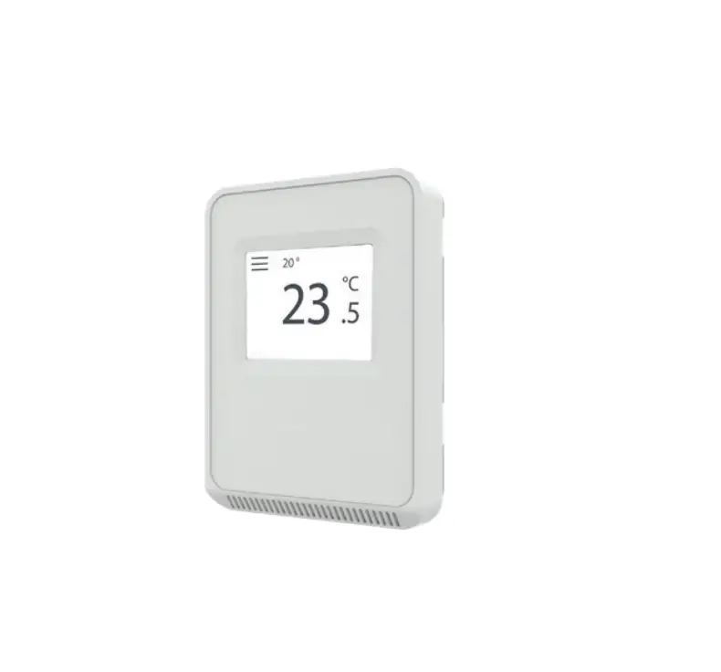
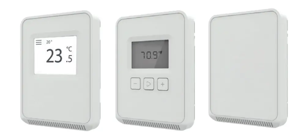
The TW2 Series of temperature sensors for living space is a versatile sensor platform for use with BAS controllers designed to accept 4 to 20mA, 0 to 5Vdc or 0 to 10Vdc outputs. TW2 Series sensors are available with three user interface options: touchscreen, LCD with three buttons and blank.
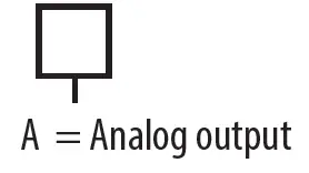
Product Identification
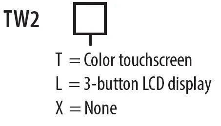
X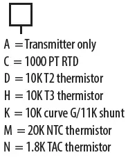
Specifications
| OPERATING ENVIRONMENT | |
| Input Power | Class 2; 20 to 30 Vdc, 24 Vac, 50 to 60 Hz |
| Analog Output | Selectable 4 to 20 mA, 0 to 5 V, 0 to 10 V |
| Operating Temp. Range | 0 to 50 °C (32 to 122 °F) |
| Operating Humidity Range | 0 to 95% RH non-condensing |
| Housing Material | High-impact ABS plastic |
| Terminal Block Torque | 0.5 to 0.6 N-m (0.37 to 0.44 in-lbf) |
| IP Rating | IP 30 |
| Mounting Location | For indoor use only. Not suitable for wet locations. |
| Surface Mount | The device can be surface mounted on Single Gang J-Box, British Standard and CE60 wall boxes |
| TEMPERATURE TRANSMITTER OPTION | |
| Sensor Type | Solid state, integrated circuit |
| Accuracy | ±0.2 °C (±0.4 °F) typical |
| Resolution | 0.1 °C (0.1 °F) |
| Range | 0 to 50 °C (32 to 122 °F) |
| DISPLAY MODELS | |
| Touchscreen | 61 mm (2.4 in), color, backlit, capacitive, 240×300 px Setpoint: 0-10Vdc. Temperature or fan speed selectable Timeout override: Display timeout* Lockout override: Touchscreen/button lockout* |
| LCD | 52mm (2.05 in), segmented with 3 buttons Setpoint: 0-10Vdc. Temperature or fan speed selectable Timeout override: Display timeout* Lockout override: Touchscreen/button lockout* |
| SETPOINTS** | |
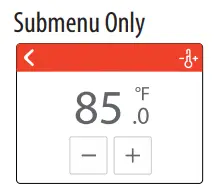
| Temperature Setpoint | 0 to 10V output Scale: 10 to 35 °C (50 to 95 °F) / 0 to 50 °C (32 to 122 °F) |
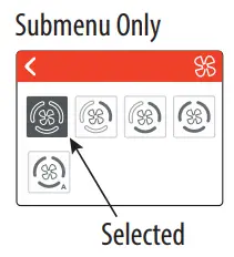
| Fan Speed Setpoint | 0 to 10V output Off 0V, Auto 1.5V, Low 3.3V, Med. 6.7V, High 10.0V |
| WIRING TERMINALS | |
| Terminal Blocks | Screw terminals, 18-24 AWG |
| Screw Terminal Torque | 0.2 N-m (2.0 in-lbF) max. |
| OVERRIDE | |
| Override Button | Display models feature a momentary-to-ground override button |
| WARRANTY | |
| Limited Warranty | 5 years |
| COMPLIANCE INFORMATION | |
| Agency Approvals | UL 916, European conformance CE: EN61000-6-2, EN61000-6-3, EN61000 Series – industrial immunity, EN 61326-1 FCC Part 15 Class B, REACH, RoHS, RCM (Australia), ICES-003 (Canada) |
*DIP switch selectable.
** One setpoint type is selectable via DIP switch on display models only.
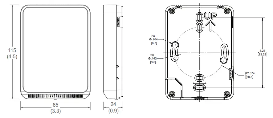
Dimensions
Functions
The TW2 Series sensor measures the temperature in a room and provides analog outputs to a controller
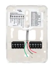
Installation
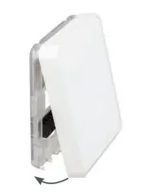
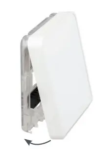
- Remove the cover from the base at the bottom of the device.

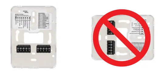
- Position the sensor base vertically on the wall 1.35 m (4.5 ft.) above the floor with the “UP” arrow facing upward. Locate away
from windows, vents and other sources of draft. If possible, do not mount on an external wall, as this may cause inaccurate temperature readings
- Pull 18 or 22 AWG cable(s) through the hole in the backplate.

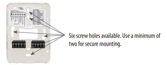
- Mount the backplate onto the wall using the screws provided

Connect the wires to the screw terminals. Do not over-tighten the screws.
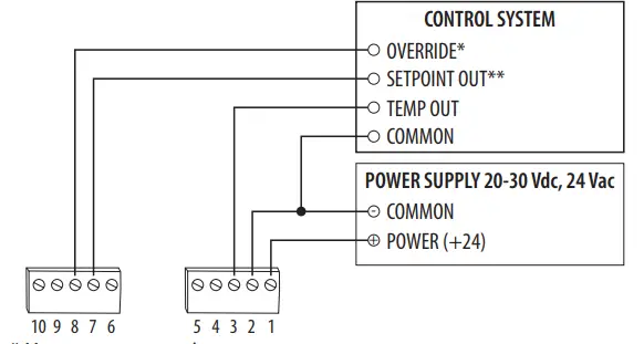
Wiring for models with temperature transmitter (except TW2LAXA):
Wiring for models with temperature transmitter (TW2LAXA only):
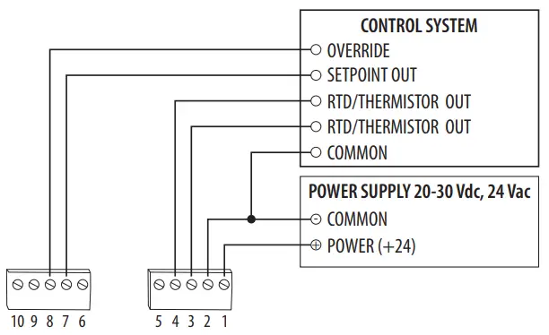
Wiring for models with RTD/thermistor:|
* Momentary to ground.
** 0-10V DIP switch selectable for temperature, RH or fan speed (off, 0V, Auto 1.5V, Low 3.3V, Medium 6.7V or high 10.0V).
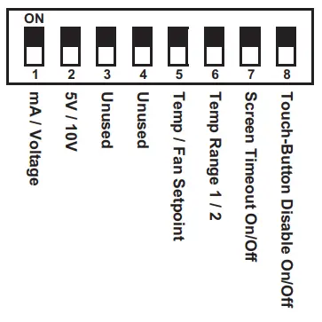
Set the DIP switches.
Switch Function Description 1 Output mode ON – 4-20mA output mode enabled OFF – Voltage output mode enabled 2 Voltage output range* ON – 0-5V output range enabled OFF 0-10V output range enabled 3 Unused Unused 4 Unused Unused 5 Setpoint output type ON – Temperature setpoint enabled (temp range selected on DIP switch 6) OFF – Fan Speed setpoint enabled 6 Setpoint output temperature range Temperature setpoint (must be enabled on DIP switch 5) ON – Temp range 1, 50 to 95 °F (10 to 35 °C) enabled OFF – Temp range 2, 32 to 122 °F (0 to 50 °C) enabled
7 Display times out and turns off after 6-10 seconds of touchscreen/button press ON – Display Timeout enabled OFF – Display Timeout disabled 8 Touchscreen touch functions and buttons are disabled ON – Touchscreen touch/button functions disabled OFF – Touchscreen touch/button functions enabled - With sensor base fully installed, align top of cover to mounting tabs on top of sensor base. Swing cover downward until it latches at the bottom.

Touchscreen Operation
=Install locking screw to secure cover in closed position.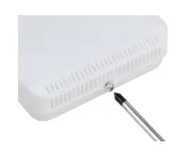
Main Screen
The touchscreen user interface displays temperature sensor output values, setpoint value and menu button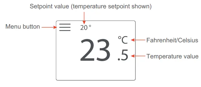
Menu Screen
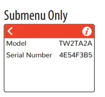
The menu screen opens when pressing the Menu button on the main screen. Integrator’s submenu, occupancy/override, Fahrenheit/Celsius, settings and setpoint submenu (temp or fan, determined by DIP switch settings) are displayed on the menu screen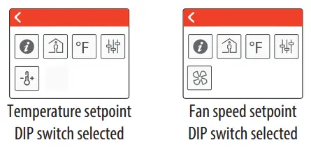
| Menu Button Functions | |
| Integrator’s Submenu Press this icon to access the Integrator’s menu. | Submenu Only |
 Occupied Override Button Press this icon to provide momentary ground output to the controller Occupied Override Button Press this icon to provide momentary ground output to the controller | Single Press Only |
| Single Press Only | |
This icon provides the ability to change the color scheme of the display | 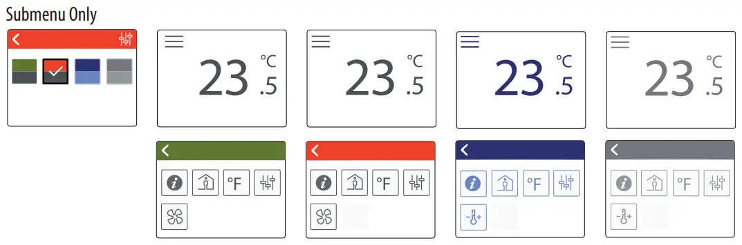 |
Click this icon to access the setpoint change menu. Mutually exclusive with fan speed, set by DIP switch.
|   |
 Fan Speed
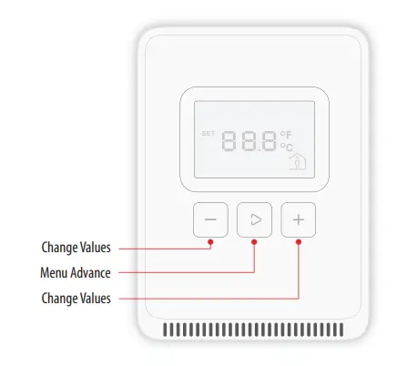
LCD Display Operation
Button Functions
Display Icons
The main screen displays sensor values for temperature and Celsius/Fahrenheit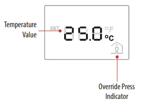
Setpoint Function
A single 0-10V setpoint (temperature or fan speed) can be selected via DIP switch.
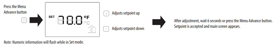
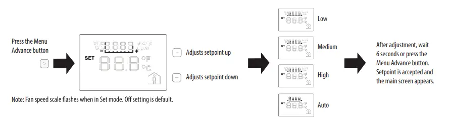
Temperature Setpoint Adjustment
Fan Speed Setpoint Adjustment
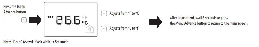
Changing Celsius and Fahrenheit Scales
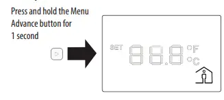
Occupied/Override Button
China RoHS Compliance Information
Environment-Friendly Use Period (EFUP) Table
This table is made according to SJ/T 11364.
O: indicates that the concentration of hazardous substance in all of the homogeneous materials for this part is below the limit as stipulated in GB/T 26572.
X: indicates that concentration of hazardous substance in at least one of the homogeneous materials used for this part is above the limit as stipulated in GB/T 26572 Z000057-0B
©2022 Veris Industries USA 800.354.8556 or +1.503.598.4564 / [email protected] 0422
Alta Labs, Enercept, Enspector, Hawkeye, Trustat, Aerospond, Veris, and the Veris ‘V’ logo are trademarks or registered trademarks of Veris Industries, L.L.C. in the USA and/or other countries.
Other companies’ trademarks are hereby acknowledged to belong to their respective owners.