resideo Temperature Sensor Installation Guide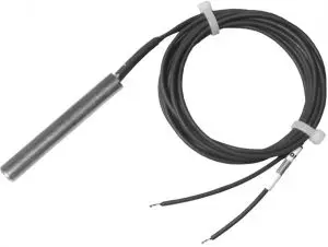
APPLICATION
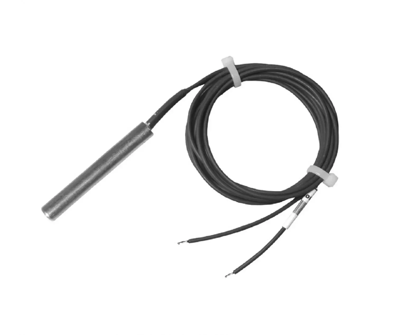
Single element 10KOhm resistive temperature sensor used with the Resideo Domestic Hot Water Module AquaReset system. Single element sensors provide only operation temperatures for a variety of temperature sensing applications including Domestic Hot Water Module detection
FEATURES
- NTC resistive 10K Ohm ± 1% at 25 °C temperature sensors.
- Sensor β=3950 for 25 °C to 66 °C (β=thermistor material constant relative to its resistance versus temperature)
- Single element sensors for water tank inlet/outlet, boiler inlet, header and outdoor temperature sensing functions.
- 32003971-003 sensor kit contains sensor and hard ware for strap-on or outdoor mounting of sensor.
- Sensors may be used for either strap-on or insertion type applications.
- Compatible immersion wells and accessories available. Refer to Resideo form number 68-0040 for more information.
SPECIFICATIONS
Sensors may be used in strap-on applications
Complementary parts such as immersion wells, mounting clamps and spring clips can be found in Resideo form #68- 0040, Immersion Wells and Compression Fittings. The immersion wells and other complementary parts must be ordered separately.
Table 1. DHW Module Sensors
| Sensor Function | Description | Temperature Range | Termination | Part Number | Installation Information |
| Water Tank Inlet/Outlet |
| -40 to +266 °F -40 to +130 °C | 42 in. leads, wires skinned and retained | 32003971-003 Kit includes sensor, anchors, mounting screws, wire nuts, clip, tie straps |
|
NOTE: Use 22 AWG two-wire twisted pair, insulated for low voltage such as Belden 8443 or equivalent and limit cable length to 50 feet (15.24 meters).
INSTALLATION
When Installing this Product…
- Read these instructions carefully. Failure to follow them could damage the product or cause a hazardous condition.
- Check the ratings given in the instructions and on the product to make sure the product is suitable for your application.
- Installer must be a trained, experienced service technician.
- After installation is complete, check out product operation as provided in these instructions and the product instructions for which the sensors are used.
Strap-On Mounting
The Domestic Hot Water Module application requires the sensing bulb to be strapped to the outside of a pipe. The 32003971-003 sensor kit includes hardware for mounting the sensor to a pipe.
![]() CAUTION
CAUTION
- Significant Calibration Shift Hazard.
- Over-tightening tie straps distorts bulb calibration.
- Do not over-tighten tie straps.
- Sand and/or clean the pipe surface as necessary in preparation for sensor mounting.
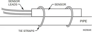
- Secure the bulb to the pipe with the tie straps. See Fig. 1.

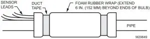
Fig. 1. Securing bulb to the pipe. - If necessary, cover the bulb with insulation, making sure it extends at least 6 inches (152mm) beyond both ends of the bulb. See Fig. 2.
IMPORTANT
Do not allow the tape to come into contact with the pipe. - Secure insulation with duct tape or foil tape. See Fig. 2.

Fig. 2. Covering bulb and pipe with insulation.
CHECKOUT
General
Refer to the end control installation documentation for final system checkout.
For troubleshooting refer to Table 2 and 3 and confirm appropriate resistance using a calibrated ohm meter.
Table 2. Thermistor Resistance at Various Temperatures in Fahrenheit.
| Temperature (°F) | Resistance (K ohms) | |||||||||
| 0 | 1 | 2 | 3 | 4 | 5 | 6 | 7 | 8 | 9 | |
| 40 | 26109 | 25400 | 24712 | 24045 | 23399 | 22771 | 22163 | 21573 | 21000 | 20445 |
| 50 | 19906 | 19383 | 18876 | 18383 | 17905 | 17440 | 16990 | 16553 | 16128 | 15715 |
| 60 | 15314 | 14925 | 14548 | 14180 | 13823 | 13477 | 13140 | 12812 | 12494 | 12185 |
| 70 | 11884 | 11592 | 11308 | 11032 | 10763 | 10502 | 10248 | 10000 | 9760 | 9526 |
| 80 | 9299 | 9078 | 8862 | 8653 | 8449 | 8250 | 8057 | 7869 | 7685 | 7507 |
| 90 | 7333 | 7165 | 7000 | 6839 | 6683 | 6531 | 6383 | 6238 | 6098 | 5961 |
| 100 | 5827 | 5697 | 5570 | 5446 | 5326 | 5208 | 5094 | 4982 | 4873 | 4767 |
| 110 | 4663 | 4562 | 4464 | 4368 | 4274 | 4183 | 4094 | 4006 | 3922 | 3839 |
| 120 | 3758 | 3679 | 3602 | 3527 | 3453 | 3382 | 3312 | 3244 | 3177 | 3112 |
| 130 | 3048 | 2986 | 2925 | 2866 | 2808 | 2752 | 2697 | 2643 | 2590 | 2538 |
| 140 | 2488 | 2439 | 2391 | 2344 | 2298 | 2253 | 2209 | 2166 | 2124 | 2083 |
| 150 | 2043 | 2004 | 1966 | 1928 | 1891 | 1856 | 1820 | 1786 | 1753 | 1720 |
| 160 | 1688 | 1656 | 1625 | 1595 | 1566 | 1537 | 1509 | 1481 | 1454 | 1427 |
| 170 | 1402 | 1376 | 1351 | 1327 | 1303 | 1280 | 1257 | 1235 | 1213 | 1191 |
| 180 | 1170 | 1150 | 1129 | 1110 | 1090 | 1071 | 1053 | 1035 | 1017 | 999 |
| 190 | 982 | 965 | 949 | 933 | 917 | 901 | 886 | 871 | 857 | 842 |
| 200 | 828 | 814 | 801 | 788 | 775 | 762 | 749 | 737 | 725 | 713 |
Table 3. Thermistor Resistance at Various Temperatures in Celsius.
| Temperature (°C) | Resistance (K ohms) | |||||||||
| 0 | 1 | 2 | 3 | 4 | 5 | 6 | 7 | 8 | 9 | |
| 0 | 32648 | 31026 | 29495 | 28049 | 26682 | 25389 | 24166 | 23010 | 21915 | 20879 |
| 10 | 19898 | 18968 | 18088 | 17253 | 16461 | 15710 | 14998 | 14322 | 13680 | 13071 |
| 20 | 12492 | 11942 | 11419 | 10922 | 10450 | 10000 | 9572 | 9165 | 8778 | 8409 |
| 30 | 8057 | 7722 | 7403 | 7099 | 6808 | 8532 | 6268 | 6016 | 5775 | 5546 |
| 40 | 5327 | 5117 | 4917 | 4726 | 4543 | 4368 | 4201 | 4042 | 3889 | 3742 |
| 50 | 3602 | 3468 | 3340 | 3217 | 3099 | 2986 | 2878 | 2774 | 2675 | 2579 |
| 60 | 2488 | 2400 | 2316 | 2235 | 2157 | 2083 | 2011 | 1942 | 1876 | 1813 |
| 70 | 1752 | 1693 | 1637 | 1582 | 1530 | 1480 | 1432 | 1385 | 1340 | 1297 |
| 80 | 1256 | 1216 | 1177 | 1140 | 1105 | 1070 | 1037 | 1005 | 974 | 944 |
| 90 | 916 | 888 | 861 | 835 | 810 | 786 | 763 | 741 | 719 | 698 |
Contact Us
Resideo Technologies, Inc.
1985 Douglas Drive North, Golden Valley, MN 55422 1-800-468-1502
69-2344EFS—02 M.S. Rev. 05-21 | Printed in United States
http://www.resideo.com/