Honeywell TruStability Board Mount Pressure Sensors Installation Guide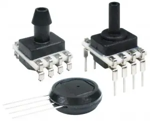
General Information
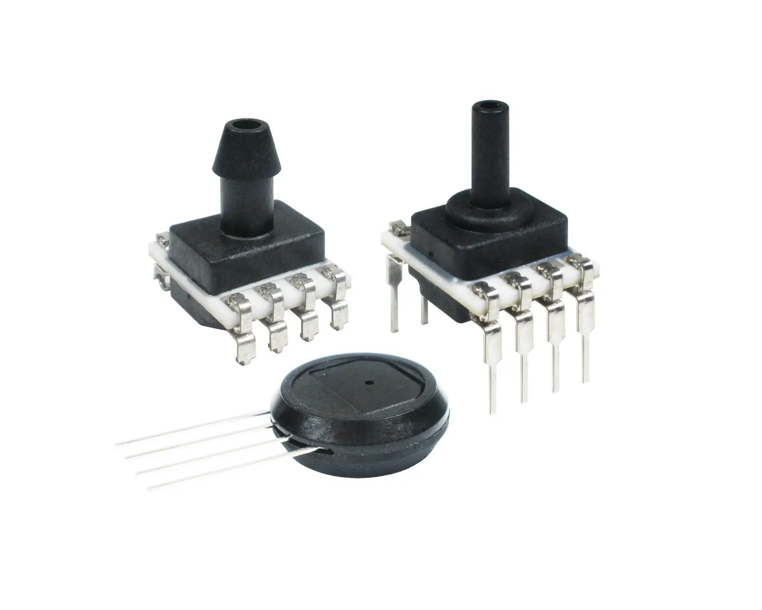
The RSC Series is a piezoresistive silicon pressure sensor offering a digital output for reading pressure over the specified full scale pressure span and temperature range. It is calibrated and temperature compensated for sensor offset, sensitivity, temperature effects, and non-linearity using a 24-bit analog-to digital converter with integrated EEPROM. Pressure data may be acquired at rates between 20 and 2000 samples per second over an SPI interface. It is intended for use with non-corrosive, non-ionic gases, such as air and other dry gases, designed and manufactured according to ISO 9001 standards, and is REACH and RoHS compliant.
Table 1. Absolute Maximum Ratings1
| Characteristic | Min. | Max. | Unit |
| Supply voltage (Vsupply) | 2.7 | 6.0 | Vdc |
| Voltage on any pin | -0.3 | Vsupply + 0.3 | V |
| Digital interface clock frequency | — | 5 | MHz |
| ESD susceptibility (human body model) | — | 2 | kV |
| Storage temperature | -40 [-40] | 85 [185] | °C [°F] |
| Soldering time and temperature: lead solder temperature (DIP) peak reflow temperature (SMT) | 4 s max. at 250 °C [482 °F] 15 s max. at 250 °C [482 °F] | ||
¹Absolute maximum ratings are the extreme limits the device will withstand without damage.
Table 2. Environmental Specifications
| Characteristic | Parameter |
| Humidity (gases only) | 0% to 95% RH, non-condensing |
| Vibration | 15 g, 10 Hz to 2 Hz |
| Shock | 100 g, 6 ms duration |
| Life1 | 1 million pressure cycles minimum |
| Solder reflow | J-STD-020-D.1 Moisture Sensitivity Level 1 (unlimited shelf life when stored at <30 °C/85 % RH) |
Table 3. Wetted Materials¹
| Component | Port 1 (Pressure Port) | Port 2 (Reference Port) |
| Ports and covers | high temperature polyamide | high temperature polyamide |
| Substrate | alumina ceramic | alumina ceramic |
| Adhesives | epoxy, silicone | epoxy, silicone |
| Electronic components | plastic, silicon, glass, solder | silicon, glass, gold |
Table 4. Sensor Pressure Types
| Pressure Type | Description |
| Absolute | Output is proportional to the difference between applied pressure and a built-in vacuum reference. |
| Differential | Output is proportional to the difference between the pressures applied to each port (Port 1 – Port 2). |
| Gage | Output is proportional to the difference between applied pressure and atmospheric (ambient) pressure. |
Table 5. Digital Operating Specifications
| Characteristic | Min. | Typ. | Max. | Unit |
| Supply voltage (Vsupply):1, 2, 3 pressure ranges >60 mbar | 6 kPa | 1 psi: 3.3 Vdc 5.0 Vdc pressure ranges <40 mbar | 4 kPa | 20 inH2O: 3.3 Vdc 5.0 Vdc | 3.0 | 3.3 | 3.6 | |
| 4.75 | 5.0 | 5.25 | Vdc | |
| 3.27 | 3.3 | 3.33 | ||
| 4.95 | 5.0 | 5.05 | ||
| Supply current: 3.3 Vdc: standby mode active mode 5.0 Vdc: standby mode active mode | — | 1.3 | — | |
| — | 1.7 | — | mA | |
| — | 2.1 | — | ||
| — | 2.6 | — | ||
| Operating temperature range4 | -40 [-40] | — | 85 [185] | °C [°F] |
| Compensated temperature range:5 | ||||
| medical industrial | 0 [32] -20 [-4] | — — | 50 [122] 85 [185] | °C [°F] |
| extended | -40 [-40] | — | 85 [185] | |
| Startup time (power up to data ready) | — | — | 0.3 | ms |
| Data rate | 20, 40, 45, 90, 175, 180, 330, 350, 600, 660, | samples per | ||
| 1000, 1200, 2000 | second | |||
| SPI voltage level: | ||||
| low high | — 80 | — — | 20 — | %Vsupply |
| Pull up on MISO, SCLK, CS_ADC, CS_EE, MOSI | 1 | — | — | kOhm |
| Accuracy6 | — | — | 0.1 | %FSS BFSL6 |
| Orientation sensitivity (±1 g):7, 9 | ||||
| pressure ranges <40 mbar | 4 kPa | 20 inH2O pressure ranges <2.5 mbar | 250 Pa | 1 inH2O | — — | ±0.1 ±0.2 | — — | %FSS8 |
Table 6. Pressure Range Specifications for ±1.6 mbar to ±10 bar

- Working Pressure: The maximum pressure that may be applied to any port of the sensor in continuous use. This pressure may be outside the operating pressure range limits (Pmin. to Pmax.) in which case the sensor may not provide a valid output until presssure is returned to within the operating pressure range. Tested to 1 million cycles, minimum.
- Overpressure: The maximum pressure which may safely be applied to the product for it to remain in specification once pressure is returned to the operating pressure range. Expo- sure to higher pressures may cause permanent damage to the product. Unless otherwise specified this applies to all available pressure ports at any temperature with the operating
temperature range. - Burst Pressure: The maximum pressure that may be applied to any port of the product without causing escape of pressure media. Product should not be expected to function after exposure to any pressure beyond the burst pressure.
- Common Mode Pressure: The maximum pressure that can be applied simultaneously to both ports of a differential pressure sensor without causing changes in specified performance.
- Total Error Band: The maximum deviation from the ideal transfer function over the entire compensated temperature and pressure range. Includes all errors due to offset, full scale
span, pressure non-linearity, pressure hysteresis, repeatability, thermal effect on offset, thermal effect on span, and thermal hysteresis (see Figure 1). - Total Error Band after Auto-Zero: The maximum deviation from the ideal transfer function over the entire compensated pressure range for a minimum of 24 hours after an auto-zero
operation. Includes all errors due to full scale span, pressure non-linearity, pressure hysteresis, and thermal effect on span. - Effective Number of Bits (ENOB: A measure of the dynamic performance of an analog-to-digital converter (ADC) and its related circuitry. ENOB is defined for the RSC Series per the following equation: ENOB = log2 (Full Scale Span/Noise).
Table 7. Pressure Range Specifications for ±160 Pa to ±1 MPa

- Working Pressure: The maximum pressure that may be applied to any port of the sensor in continuous use. This pressure may be outside the operating pressure range limits (Pmin. to Pmax.) in which case the sensor may not provide a valid output until presssure is returned to within the operating pressure range. Tested to 1 million cycles, minimum.
- Overpressure: The maximum pressure which may safely be applied to the product for it to remain in specification once pressure is returned to the operating pressure range. Expo- sure to higher pressures may cause permanent damage to the product. Unless otherwise specified this applies to all available pressure ports at any temperature with the operating temperature range.
- Burst Pressure: The maximum pressure that may be applied to any port of the product without causing escape of pressure media. Product should not be expected to function after exposure to any pressure beyond the burst pressure.
- Common Mode Pressure: The maximum pressure that can be applied simultaneously to both ports of a differential pressure sensor without causing changes in specified performance.
- Total Error Band: The maximum deviation from the ideal transfer function over the entire compensated temperature and pressure range. Includes all errors due to offset, full scale span, pressure non-linearity, pressure hysteresis, repeatability, thermal effect on offset, thermal effect on span, and thermal hysteresis (see Figure 1).
- Total Error Band after Auto-Zero: The maximum deviation from the ideal transfer function over the entire compensated pressure range for a minimum of 24 hours after an auto-zero operation. Includes all errors due to full scale span, pressure non-linearity, pressure hysteresis, and thermal effect on span.
- Effective Number of Bits (ENOB): A measure of the dynamic performance of an analog-to-digital converter (ADC) and its related circuitry. ENOB is defined for the RSC Series per the following equation: ENOB = log2 (Full Scale Span/Noise).
Table 8. Pressure Range Specifications for ±0.5 inH2 O to ±150 psi

- Working Pressure: The maximum pressure that may be applied to any port of the sensor in continuous use. This pressure may be outside the operating pressure range limits (Pmin. to Pmax.) in which case the sensor may not provide a valid output until presssure is returned to within the operating pressure range. Tested to 1 million cycles, minimum.
- Overpressure: The maximum pressure which may safely be applied to the product for it to remain in specification once pressure is returned to the operating pressure range. Expo- sure to higher pressures may cause permanent damage to the product. Unless otherwise specified this applies to all available pressure ports at any temperature with the operating temperature range.
- Burst Pressure: The maximum pressure that may be applied to any port of the product without causing escape of pressure media. Product should not be expected to function after exposure to any pressure beyond the burst pressure.
- Common Mode Pressure: The maximum pressure that can be applied simultaneously to both ports of a differential pressure sensor without causing changes in specified performance.
- Total Error Band: The maximum deviation from the ideal transfer function over the entire compensated temperature and pressure range. Includes all errors due to offset, full scale span, pressure non-linearity, pressure hysteresis, repeatability, thermal effect on offset, thermal effect on span, and thermal hysteresis (see Figure 1).
- Total Error Band after Auto-Zero: The maximum deviation from the ideal transfer function over the entire compensated pressure range for a minimum of 24 hours after an auto-zero operation. Includes all errors due to full scale span, pressure non-linearity, pressure hysteresis, and thermal effect on span.
- Effective Number of Bits (ENOB): A measure of the dynamic performance of an analog-to-digital converter (ADC) and its related circuitry. ENOB is defined for the RSC Series perthe following equation: ENOB = log2 (Full Scale Span/Noise).
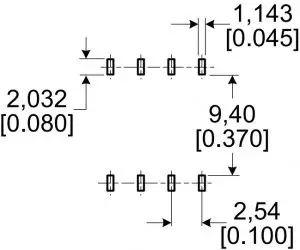
DIP Package Dimensional
Figure 3. DIP Package Dimensional Drawings (For reference only: mm [in].)
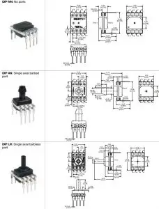
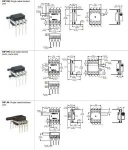
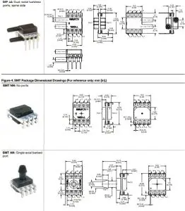
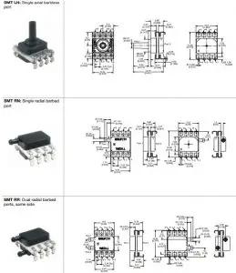
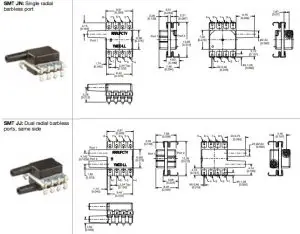
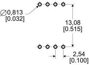
Figure 5. Recommended PCB Pad Layouts
- DIP

- SMT

Pinout
Table 9. Pinout
| Pin | Name | Description |
| 1 | SCLK | External Clock Source |
| 2 | DRDY | Data Ready: Active Low |
| 3 | DIN | Serial Data Input |
| 4 | CS_ADC | ADC Chip Select: Active Low |
| 5 | GND | Ground |
| 6 | VCC | Positive Supply Voltage |
| 7 | CS_EE | EEPROM Chip Select: Active Low |
| 8 | DOUT | Serial Data Output |
Figure 6. Recommended Circuit
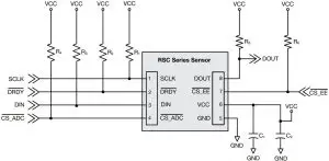
- Pull-up resistors: R1 =R2 =R3 =R4 =R5 =R6 = 1 kOhm
- Supply filter capacitors: C1 = 0.1 uF, C2 = 10 uF
Note: R1, R2,R3, R5 are optional
![]() WARNING
WARNING
PERSONAL INJURY
- DO NOT USE these products as safety or emergency stop devices or in any other application where failure of the product could result in personal injury.
- Failure to comply with these instructions could result in death or serious injury.
Warranty/Remedy
Honeywell warrants goods of its manufacture as being free of defective materials and faulty workmanship during the applicable warranty period. Honeywell’s standard product warranty applies unless agreed to otherwise by Honeywell in writing; please refer to your order acknowledgement or consult your local sales office for specific warranty details. If warranted goods are returned to Honeywell during the period of coverage, Honeywell will repair or replace, at its option, without charge those items that Honeywell, in its sole discretion, finds defective. The foregoing is buyer’s sole remedy and is in lieu of all other warranties, expressed or implied, including those of merchant ability and fitness for a particular purpose. In no event shall Honeywell be liable for consequential, special, or indirect damages.
While Honeywell may provide application assistance personally, through our literature and the Honeywell web site, it is buyer’s sole responsibility to determine the suitability of the product in the application.
Specifications may change without notice. The information we supply is believed to be accurate and reliable as of this writing.
However, Honeywell assumes no responsibility for its use.
Customer Service
Honeywell Advanced Sensing Technologies services its customers through a worldwide network of sales offices and distributors. For application assistance, current specifications, pricing or the nearest Authorized Distributor, visit sps.honeywell.com/ast or call:
USA/Canada: +1 302 613 4491
Latin America: +1 305 805 8188
Europe: +44 1344 238258
Japan: +81 (0) 3-6730-7152
Singapore: +65 6355 2828
Greater China: +86 4006396841


 Installation Guide")


