![]() INSTALLATION INSTRUCTIONS FOR THE
INSTALLATION INSTRUCTIONS FOR THE
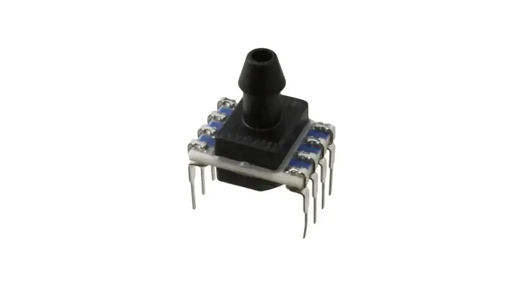
BASIC AMPLIFIED BOARD MOUNT PRESSURE SENSORS, ABP SERIES
32305127 Issue H
GENERAL SPECIFICATIONS
The ABP Series are piezoresistive silicon pressure sensors offering a ratiometric analog or digital output for reading pressure over the specified full scale pressure span and temperature range. They are calibrated and temperature compensated for sensor offset, sensitivity, temperature effects and accuracy errors (which include non-linearity, repeatability and hysteresis) using an on-board Application Specific Integrated Circuit (ASIC). Calibrated output values for pressure are updated at approximately 1 kHz for analog and 2 kHz for digital. All products are designed and manufactured according to ISO 9001 standards.
CLEANING
CAUTION
IMPROPER CLEANING
Avoid cleaning the sensor; however, if it must be cleaned ensure cleaning fluids, such as appropriate alcohols or fluorinated solvents, are used based on the type of contaminants to be removed. Do not immerse the sensor. Failure to comply with these instructions may result in product damage.
| TABLE 1. ABSOLUTE MAXIMUM RATINGS1 | |||
| CHARACTERISTIC | MIN. | MAX. | UNIT |
| Supply voltage (Vsupply) | -0.3 | 6.0 | Vdc |
| Voltage on any pin | -0.3 | Vsupply + 0.3 | V |
| Digital interface clock frequency: I2C SPI | 100 50 | 400 800 | kHz |
| ESD susceptibility (human body model) | 2 | — | kV |
| Storage temperature | -40 [-40] | 85 [185] | °C [°F] |
| Soldering time and temperature: lead solder temperature (DIP) peak reflow temperature (Leadless SMT, SMT) | 4 s max. at 250°C [482°F] 15 s max. at 250°C [482°F] | ||
1Absolute maximum ratings are the extreme limits the device will withstand without damage.
| TABLE 2. ENVIRONMENTAL SPECIFICATIONS | |
| CHARACTERISTIC | PARAMETER |
| Humidity: all external surfaces internal surfaces of Liquid Media Option (T, V, B, C, F, G) internal surfaces of Dry Gases Option (N, D) | 0 %RH to 95 %RH, non-condensing 0 %RH to 100 %RH, condensing 0 %RH to 95 %RH, non-condensing |
| Vibration | 15 g, 10 Hz to 2 kHz |
| Shock | 100 g, 6 ms duration |
| Life1 | 1 million pressure cycles minimum |
| Solder reflow | J-STD-020-D.1 Moisture Sensitivity Level 1 (unlimited shelf life when stored at <30°C/85 %RH) |
| Certification (silicone gel coating option: Port 1 only) | NSF-169, BPA Free, LFGB |
1Life may vary depending on specific application in which the sensor is used.
| TABLE 3. WETTED MATERIALS1 | |||
| COMPONENT | PRESSURE PORT 1 (P1) | PRESSURE PORT 2 (P2) | |
| DRY GAS OPTION | LIQUID MEDIA OPTION | ||
| Ports and covers | high temperature polyamide | ||
| Metal gel ring | — | 304 SST | — |
| Substrate | alumina ceramic | — | alumina ceramic |
| Adhesives | epoxy, silicone | epoxy, silicone gel | epoxy, silicone |
| Electronic components | silicon, glass, gold, aluminum | — | silicon |
1 Contact Honeywell Customer Service for detailed material information.
| TABLE 4. SENSOR PRESSURE TYPES | |
| PRESSURE TYPE | DESCRIPTION |
| Gage | Output is proportional to the difference between applied pressure and atmospheric (ambient) pressure. |
| Differential | Output is proportional to the difference between the pressures applied to each port (Port 1 – Port 2). |
| TABLE 5. OPERATING SPECIFICATIONS | |||||||
| CHARACTERISTIC | ANALOG | DIGITAL | UNIT | ||||
| MIN. | TYP. | MAX. | MIN. | TYP. | MAX. | ||
| Supply voltage (Vsupply):1, 2, 3 3.3 Vdc 5.0 Vdc | 3.0 4.75 | 3.3 5.0 | 3.6 5.25 | 3.0 4.75 | 3.3 5.0 | 3.6 5.25 | Vdc |
| Supply current: 3.3 Vdc 5.0 Vdc sleep mode option | — — — | 2.1 2.7 — | 2.8 3.8 — | — — — | 3.1 3.7 1 | 3.9 4.6 10 | mA mA mA |
| Operating temperature range4 | -40 [-40] | — | 85 [185] | -40 [-40] | — | 85 [185] | °C [°F] |
| Compensated temperature range5 | 0 [-32] | — | 50 [122] | 0 [-32] | — | 50 [122] | °C [°F] |
| Temperature output option6 | — | — | — | — | ±4 | — | °C |
| Startup time (power up to data ready) | — | — | 5 | — | — | 3 | ms |
| Response time | — | 1 | — | — | 0.46 | — | ms |
| Clipping limit: upper lower | — 2.5 | — — | 97.5 — | — — | — — | — — | %Vsupply |
| I2C/SPI voltage level: low high | — — | — — | — — | — 80 | — — | 20 — | %Vsupply |
| Pull up on SDA/MISO, SCL/SCLK, SS | — | — | — | 1 | — | — | kOhm |
| Total Error Band7 | — | — | ±1.5 | — | — | ±1.5 | %FSS8 |
| Accuracy9 | — | — | ±0.25 | — | — | ±0.25 | %FSS BFSL |
| Long term stability (1000 hr, 25°C [77°F]) | — | — | ±0.25 | — | — | ±0.25 | %FSS |
| Output resolution | 0.03 — | — — | — — | — 12 | — — | — — | %FSS bits |
- Sensors are either 3.3 Vdc or 5.0 Vdc based on the catalog listing selected.
- Ratiometricity of the sensor (the ability of the device output to scale to the supply voltage) is achieved within the specified operating voltage.
- The sensor is not reverse polarity protected. Incorrect application of supply voltage or ground to the wrong pin may cause electrical failure.
- Operating temperature range: The temperature range over which the sensor will produce an output proportional to pressure.
- Compensated temperature range: The temperature range over which the sensor will produce an output proportional to pressure within the specified performance limits.
- Temperature Output Option: Typical temperature output error over the compensated temperature range of 0°C to 50°C. Operation in Sleep Mode may affect temperature output error depending on duty cycle.
- Total Error Band: The maximum deviation from the ideal transfer function over the entire compensated temperature and pressure range. Includes all errors due to offset, full scale span, pressure non-linearity, pressure hysteresis, repeatability, thermal effect on offset, thermal effect on span, and thermal hysteresis.
- Full Scale Span (FSS): The algebraic difference between the output signal measured at the maximum (Pmax.) and minimum (Pmin.) limits of the pressure range.
- Accuracy: The maximum deviation in output from a Best Fit Straight Line (BFSL) fitted to the output measured over the pressure range at 25°C [77°F]. Includes all errors due to pressure non-linearity, pressure hysteresis, and non-repeatability.
| TABLE 6. SENSOR OUTPUT AT SIGNIFICANT PERCENTAGES (DIGITAL VERSIONS ONLY) | ||
| % OUTPUT | DIGITAL COUNTS | |
| DECIMAL | HEX | |
| 0 | 0 | 0x0000 |
| 10 | 1638 | 0x0666 |
| 50 | 8192 | 0x2000 |
| 90 | 14746 | 0x399A |
| 100 | 16383 | 0x3FFF |
| TABLE 7. PRESSURE RANGE SPECIFICATIONS | ||||||||
| PRESSURE RANGE | PRESSURE RANGE | UNIT | OVERPRESSURE1 | BURST PRESSURE2 | COMMON MODE PRESSURE3 | |||
| PMIN. | PMAX. | PORT 1 (P1) | PORT 2 (P2) | PORT 1 (P1) | PORT 2 (P2) | |||
1 psi to 150 psi
Differential
| 060MD | -60 | 60 | mbar | 2000 | 850 | 3500 | 1000 | 10000 |
| 100MD | -100 | 100 | mbar | 4000 | 1400 | 7000 | 2500 | 10000 |
| 160MD | -160 | 160 | mbar | 4000 | 1400 | 7000 | 2500 | 10000 |
| 250MD | -250 | 250 | mbar | 4000 | 1400 | 7000 | 2500 | 10000 |
| 400MD | -400 | 400 | mbar | 6000 | 2000 | 19000 | 4000 | 10000 |
| 600MD | -600 | 600 | mbar | 6000 | 2000 | 19000 | 4000 | 10000 |
| 001BD | -1 | 1 | bar | 17 | 4 | 19 | 8 | 17 |
| 1.6BD | -1.6 | 1.6 | bar | 17 | 8 | 19 | 16 | 17 |
| 2.5BD | -2.5 | 2.5 | bar | 17 | 8 | 19 | 16 | 17 |
| 004BD | -4.0 | 4.0 | bar | 17 | 16 | 19 | 19 | 17 |
Gage
| 060MG | 0 | 60 | mbar | 2000 | — | 3500 | — | 5500 |
| 100MG | 0 | 100 | mbar | 2000 | — | 3500 | — | 10000 |
| 160MG | 0 | 160 | mbar | 2000 | — | 3500 | — | 10000 |
| 250MG | 0 | 250 | mbar | 4000 | — | 7000 | — | 10000 |
| 400MG | 0 | 400 | mbar | 6000 | — | 19000 | — | 10000 |
| 600MG | 0 | 600 | mbar | 6000 | — | 19000 | — | 10000 |
| 001BG | 0 | 1 | bar | 17 | — | 19 | — | 17 |
| 1.6BG | 0 | 1.6 | bar | 17 | — | 19 | — | 17 |
| 2.5BG | 0 | 2.5 | bar | 17 | — | 19 | — | 17 |
| 004BG | 0 | 4 | bar | 17 | — | 19 | — | 17 |
| 006BG | 0 | 6 | bar | 17 | — | 19 | — | 17 |
| 010BG | 0 | 10 | bar | 17 | — | 19 | — | 17 |
6 kPa to 1 MPa
Differential
| 006KD | -6 | 6 | kPa | 200 | 85 | 350 | 100 | 1000 |
| 010KD | -10 | 10 | kPa | 400 | 140 | 700 | 250 | 1000 |
| 016KD | -16 | 16 | kPa | 400 | 140 | 700 | 250 | 1000 |
| 025KD | -25 | 25 | kPa | 400 | 140 | 700 | 250 | 1000 |
| 040KD | -40 | 40 | kPa | 600 | 200 | 1900 | 400 | 1000 |
| 060KD | -60 | 60 | kPa | 600 | 200 | 1900 | 400 | 1000 |
| 100KD | -100 | 100 | kPa | 1700 | 400 | 1900 | 800 | 1700 |
| 160KD | -160 | 160 | kPa | 1700 | 800 | 1900 | 1600 | 1700 |
| 250KD | -250 | 250 | kPa | 1700 | 800 | 1900 | 1600 | 1700 |
| 400KD | -400 | 400 | kPa | 1700 | 1600 | 1900 | 1900 | 1700 |
Gage
| 006KG | 0 | 6 | kPa | 200 | — | 350 | — | 550 |
| 010KG | 0 | 10 | kPa | 200 | — | 350 | — | 1000 |
| 016KG | 0 | 16 | kPa | 200 | — | 350 | — | 1000 |
| 025KG | 0 | 25 | kPa | 400 | — | 700 | — | 1000 |
| 040KG | 0 | 40 | kPa | 600 | — | 1900 | — | 1000 |
| 060KG | 0 | 60 | kPa | 600 | — | 1900 | — | 1000 |
| 100KG | 0 | 100 | kPa | 1700 | — | 1900 | — | 1700 |
| 160KG | 0 | 160 | kPa | 1700 | — | 1900 | — | 1700 |
| 250KG | 0 | 250 | kPa | 1700 | — | 1900 | — | 1700 |
| 400KG | 0 | 400 | kPa | 1700 | — | 1900 | — | 1700 |
| 600KG | 0 | 600 | kPa | 1700 | — | 1900 | — | 1700 |
| 001GG | 0 | 1 | MPa | 1.7 | — | 1.9 | — | 1.7 |
Advanced Sensing Technologies
| TABLE 7. PRESSURE RANGE SPECIFICATIONS, CONTINUED | ||||||||
| PRESSURE RANGE | PRESSURE RANGE | UNIT | OVERPRESSURE1 | BURST PRESSURE2 | COMMON MODE PRESSURE3 | |||
| PMIN. | PMAX. | PORT 1 (P1) | PORT 2 (P2) | PORT 1 (P1) | PORT 2 (P2) | |||
1 psi to 150 psi
Differential
| 001PD | -1 | 1 | psi | 30 | 10 | 50 | 15 | 150 |
| 005PD | -5 | 5 | psi | 90 | 30 | 275 | 40 | 150 |
| 015PD | -15 | 15 | psi | 250 | 60 | 275 | 120 | 250 |
| 030PD | -30 | 30 | psi | 250 | 120 | 275 | 240 | 250 |
| 060PD | -60 | 60 | psi | 250 | 250 | 275 | 275 | 250 |
Gage
| 001PG | 0 | 1 | psi | 30 | — | 50 | — | 150 |
| 005PG | 0 | 5 | psi | 90 | — | 275 | — | 150 |
| 015PG | 0 | 15 | psi | 250 | — | 275 | — | 250 |
| 030PG | 0 | 30 | psi | 250 | — | 275 | — | 250 |
| 060PG | 0 | 60 | psi | 250 | — | 275 | — | 250 |
| 100PG | 0 | 100 | psi | 250 | — | 275 | — | 250 |
| 150PG | 0 | 150 | psi | 250 | — | 275 | — | 250 |
- Overpressure: The maximum pressure which may safely be applied to the product for it to remain in specification once pressure is returned to the operating pressure range. Exposure to higher pressures may cause permanent damage to the product. Unless otherwise specified this applies to all available pressure ports at any temperature with the operating temperature range.
- Burst pressure: The maximum pressure that may be applied to the specified port (P1 or P2) of the product without causing escape of pressure media. Product should not be expected to function after exposure to any pressure beyond the burst pressure.
- Common mode pressure: The maximum pressure that can be applied simultaneously to both ports of a differential pressure sensor without causing changes in specified performance.
FIGURE 1. RECOMMENDED FILTER CAP
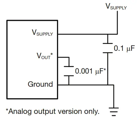
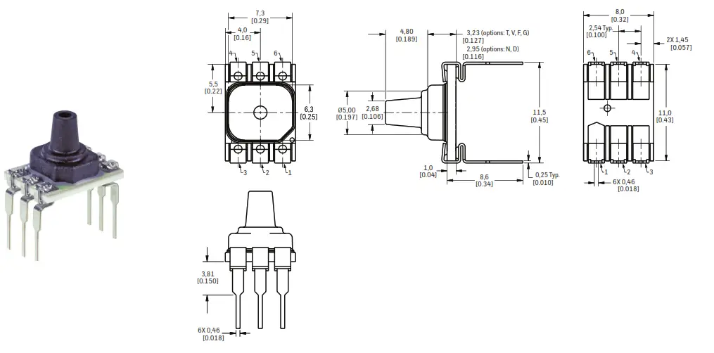
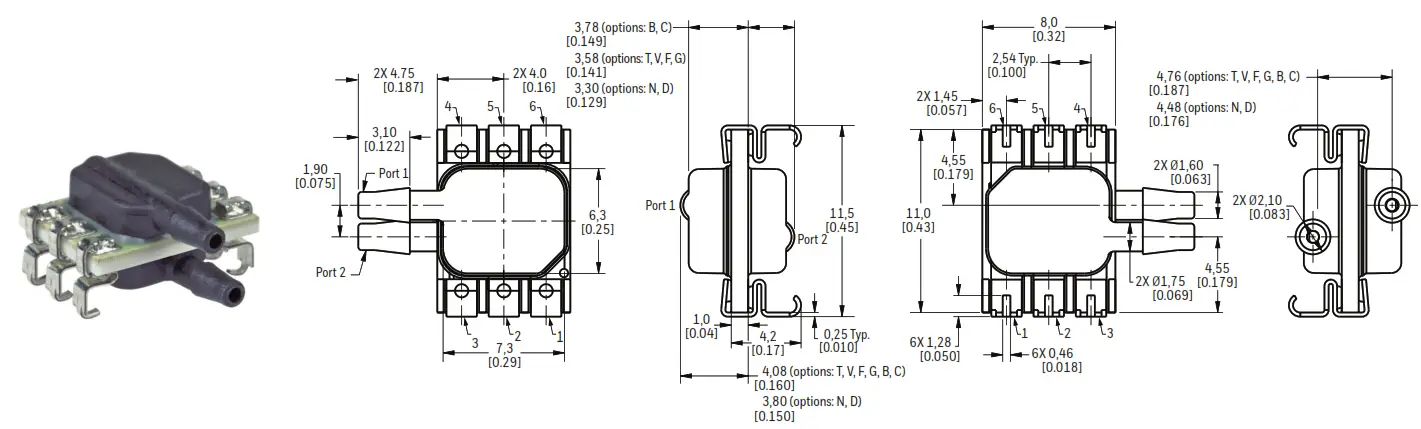
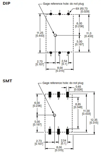
FIGURE 2. DIP PACKAGE DIMENSIONAL DRAWINGS (FOR REFERENCE ONLY: MM [IN].)
DIP NN: No port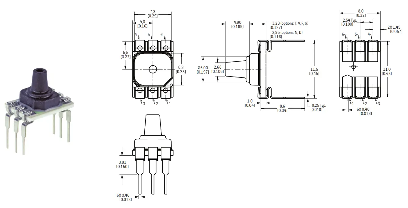
DIP AN: Single axial barbed port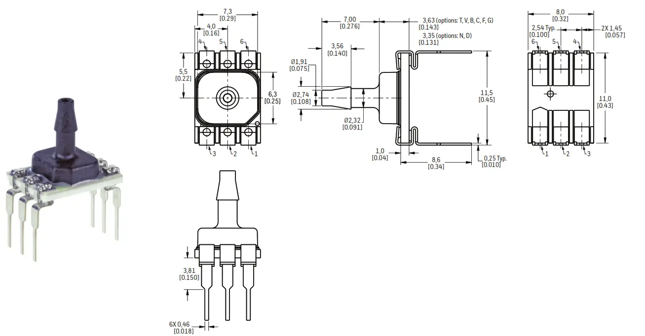
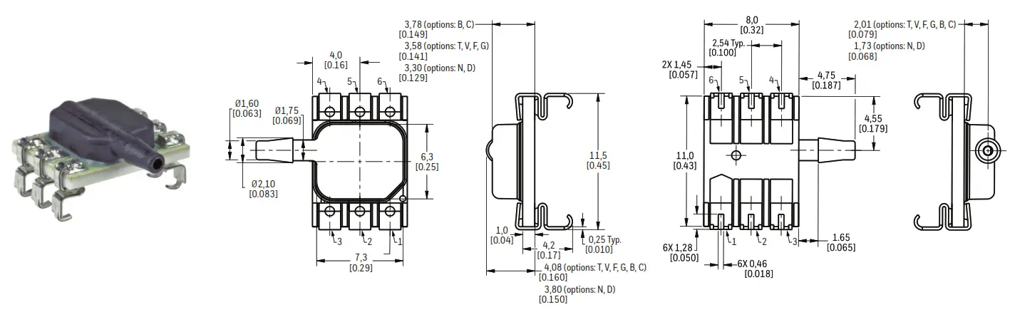
FIGURE 2. DIP PACKAGE DIMENSIONAL DRAWINGS (CONTINUED)
DIP LN: Single axial barbless port
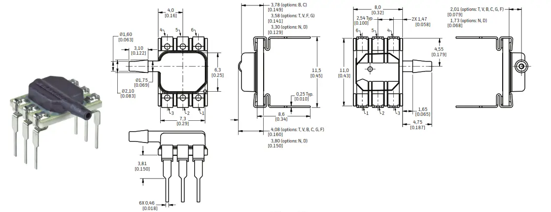
DIP JN: Single radial barbless port
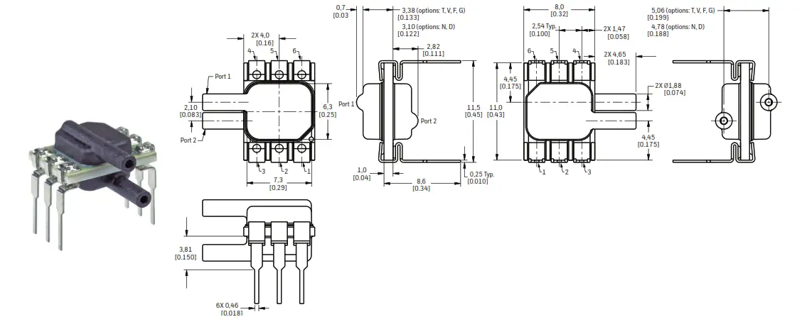
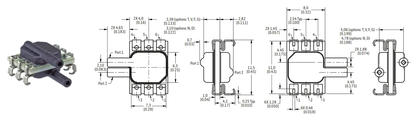
FIGURE 2. DIP PACKAGE DIMENSIONAL DRAWINGS (CONTINUED)
DIP JJ: Dual radial barbless ports, same side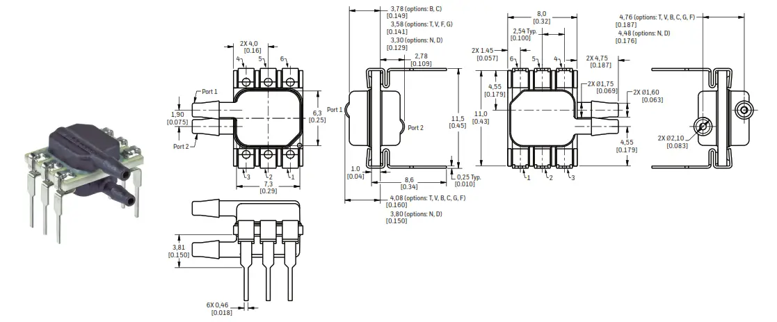
DIP RN: Single radial barbed port
DIP RR: Dual radial barbed ports, same side
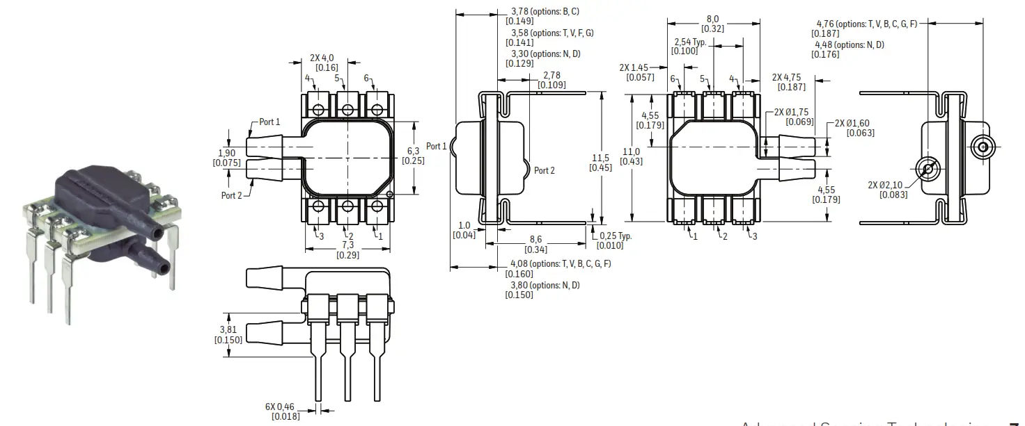
FIGURE 3. SMT PACKAGE DIMENSIONAL DRAWINGS (FOR REFERENCE ONLY: MM [IN].)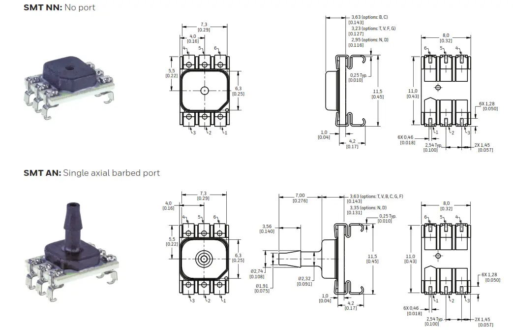
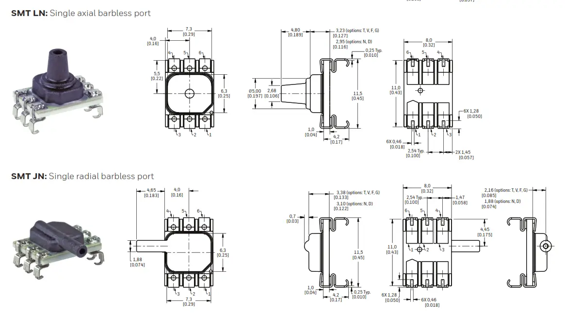
FIGURE 3. SMT PACKAGE DIMENSIONAL DRAWINGS (CONTINUED)
SMT JJ: Dual radial barbless ports, same side
SMT RN: Single radial barbed port
SMT RR: Dual radial barbed ports, both sides
BASIC AMPLIFIED BOARD MOUNT PRESSURE SENSORS, ABP SERIES
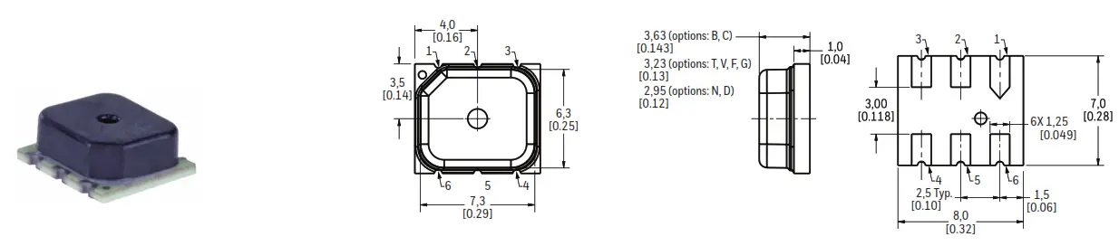
FIGURE 4. LEADLESS SMT PACKAGE DIMENSIONAL DRAWINGS (FOR REFERENCE ONLY: MM [IN].)
Leadless SMT NN: No port
Leadless SMT AN: Single axial barbed port
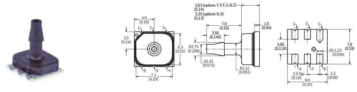
Leadless SMT LN: Single axial barbless port
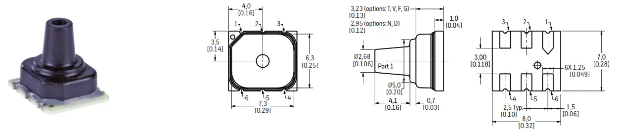
TABLE 8. PINOUTS
| OUTPUT TYPE | PIN 1 | PIN 2 | PIN 3 | PIN 4 | PIN 5 | PIN 6 |
| I2C | GND | Vsupply | INT | NC | SDA | SCL |
| SPI | GND | Vsupply | SS | NC | MISO | SCLK |
| analog | GND | NC | Vout | NC | NC | Vsupply |
BASIC AMPLIFIED BOARD MOUNT PRESSURE SENSORS, ABP SERIES
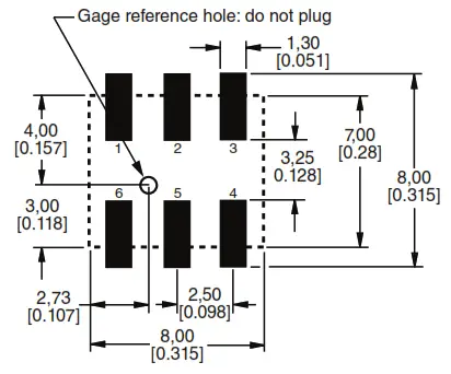
FIGURE 5. RECOMMENDED PCB LAYOUTS
Leadless SMT
![]() WARNING
WARNING
PERSONAL INJURY
DO NOT USE these products as safety or emergency stop devices or in any other application where failure of the product could result in personal injury.
Failure to comply with these instructions could result in death or serious injury.
WARRANTY/REMEDY
Honeywell warrants goods of its manufacture as being free of defective materials and faulty workmanship during the applicable warranty period. Honeywell’s standard product warranty applies unless agreed to otherwise by Honeywell in writing; please refer to your order acknowledgement or consult your local sales office for specific warranty details. If warranted goods are returned to Honeywell during the period of coverage, Honeywell will repair or replace, at its option, without charge those items that Honeywell, in its sole discretion, finds defective. The foregoing is buyer’s sole remedy and is in lieu of all other warranties, expressed or implied, including those of merchantability and fitness for a particular purpose.
In no event shall Honeywell be liable for consequential, special, or indirect damages.
While Honeywell may provide application assistance personally, through our literature and the Honeywell web site, it is buyer’s sole responsibility to determine the suitability of the product in the application.
Specifications may change without notice. The information we supply is believed to be accurate and reliable as of this writing.
However, Honeywell assumes no responsibility for its use.
FOR MORE INFOR MATION
Honeywell Sensing and Internet of Things services its customers through a worldwide network of sales offices and distributors. For application assistance, current specifications, pricing, or the nearest Authorized Distributor, visit sensing.honeywell.com or call:
| USA/Canada | +302 613 4491 |
| Latin America | +1 305 805 8188 |
| Europe | +44 1344 238258 |
| Japan | +81 (0) 3-6730-7152 |
| Singapore | +65 6355 2828 |
| Greater China | +86 4006396841 |
Honeywell
Advanced Sensing Technologies
830 East Arapaho Road
Richardson, TX 75081
sps.honeywell.com.ast
32305127-H-EN | H | 05/21
© 2021 Honeywell International Inc. All rights reserved.


