Honeywell HON 200 Gas Pressure Regulator
Gas Pressure Regulator HON 200
- Model: 200.20
- Operating and Maintenance Instructions / Spare Parts
- Serving the Gas Industry Worldwide
- Edition: 01/2017
Product Information
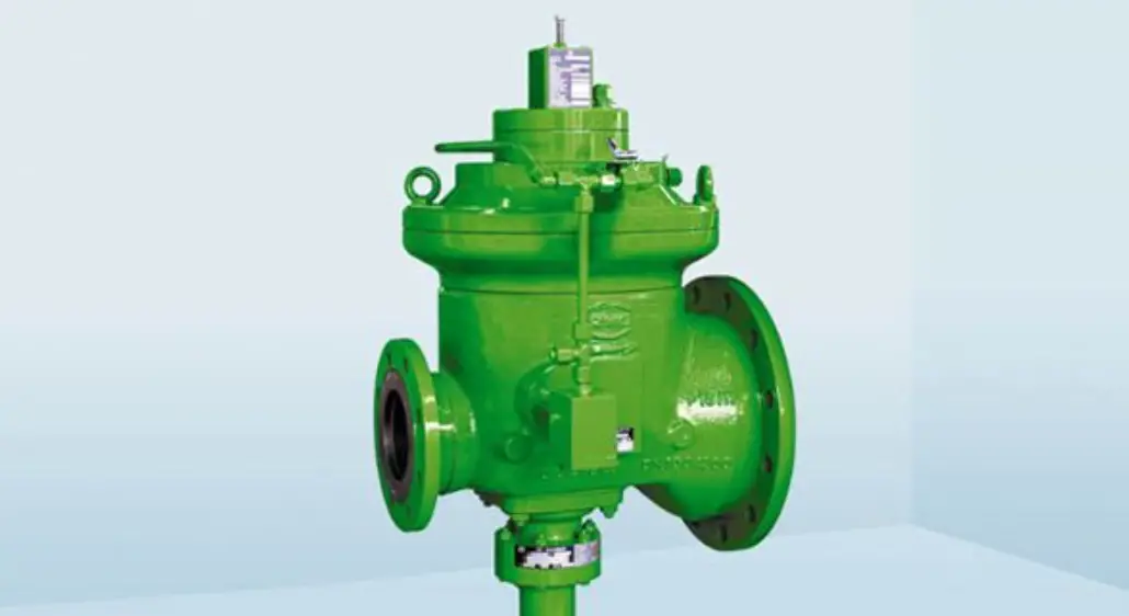
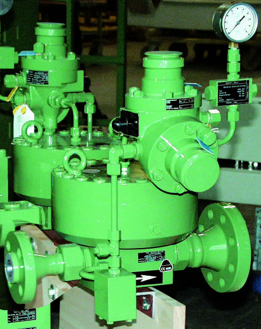
The gas pressure regulator HON 200 is designed for use in gas pressure stations. It is available in different versions and dimensions, as described in the general description 200.00. The regulator is equipped with various spare parts, which are detailed in separate brochures for the pilot (RS 10d), filter (HON 905), and HON 650.
To ensure proper installation and operation of the regulator, it is recommended to refer to the General Operating Instructions for Gas Pressure Regulators and Safety Devices brochure. This brochure provides guidance on fitting the valve into the gas line, commissioning, and troubleshooting.
The construction, set-up, supervision, and maintenance of gas pressure stations should comply with the technical rules issued by DVGW (German Technical and Scientific Association for Gas and Water) Worksheets G 490, G 491, and G 495.
The frequency of maintenance for the HON 200 regulator depends on the prevailing conditions and the type of gas being regulated. It is advised to follow the recommendations provided in the DVGW Worksheets G 495 for determining maintenance intervals.
During maintenance, all parts of the regulator should be cleaned and visually inspected. Special attention should be given to sealings, diaphragms, and moving parts. Damaged parts must be replaced with new ones. The maintenance instructions refer to item numbers that correspond to spare parts drawings and lists.
It is recommended to keep spare parts that are marked in the spare parts lists in stock for immediate availability during maintenance.
Product Usage Instructions
Throttling Valve (51)
The throttling valve (51) should be fully open for quick reaction. If the pilot HON 650 or RS 10d lacks stability and cannot be resolved through load limiting pressure adjustment, regulating stability can be achieved by turning the throttling valve (51) clockwise.
Valve Stem (23)
To maintain the valve stem (23), remove the nut (22, 27, 58, 60) and use a hexagonal screwdriver SW 4. This can also be done when mounting the actuator with the screw connection (29).
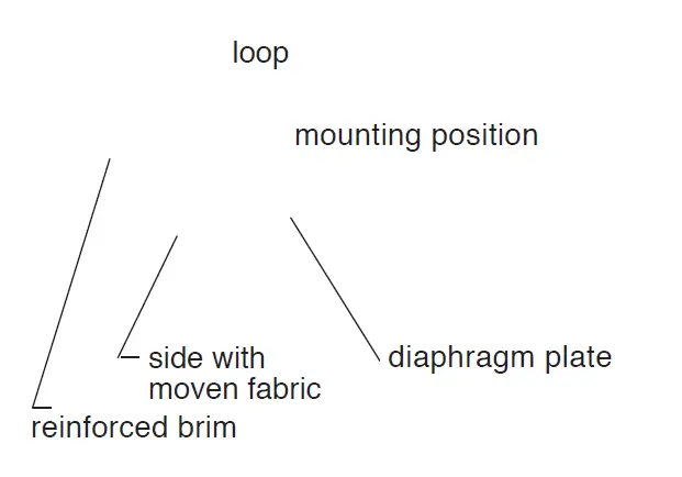
Diaphragm (7)
Lubricate the reinforced brim of the diaphragm (7) with o-ring grease according to the lubricant table. Position the diaphragm correctly, ensuring that the side with woven fabric and imprint “Gewebeseite” faces the diaphragm plate (8). To achieve correct loop formation, push the diaphragm down past the diaphragm plate using a blunt object, avoiding pointed objects.
NOTE: Always refer to the user manual and follow the manufacturer’s instructions for proper usage and maintenance of the gas pressure regulator HON 200.
General
The “General description 200.00” for the gas pressure regulator of series HON 200 contains technical data, versions and dimensions.
The spare parts are described in the following brochures:
- Pilot: RS 10d
General description
Operation and maintenance, Spare parts
610.00
610.20 - HON 650
General description
Operation and maintenance, Spare parts
650.00
650.20 - Filter: HON 905
General description
Operation and maintenance, Spare parts
905.00
905.20
Our brochure “General Operating Instructions for Gas Pressure Regulators and Safety Devices” will be useful to fit the valve into the line, put into service and find faults that might disturb the operation.
The construction, set-up, supervision and maintenance of gas pressure stations are subject to special technical rules which should be strictly observed, in particular those given by the DVGW-Worksheets G 490, G 491, and G 495.
The frequency of periodical maintenance to be foreseen for the gas pressure regulator HON 200 should be determined according to the prevailing conditions and the type and composition of the gaseous medium.
We, therefore, abstain from imposing any fixed intervals and would rather refer to the recommendations given by the DVGW Worksheets G 495.
For maintenance all parts are to be cleaned and subjected to a thorough visual inspection. A visual inspection should not be omitted when the course of operation or functional tests have shown lack of regulating accuracy.
Particular care should be given to the checking of sealings and diaphragms, as well as carrying and moving parts. Damaged parts should be replaced by new ones.
The item numbers referred to in the maintenance instructions are identical with those of spare parts drawings and spare parts lists.
We recommend to keep all parts that are specially marked in the spare parts lists in stock for prompt maintenance availability.
Special Operating Instructions
Throttling valve (51)
The throttling valve (51) should be fully open (for quick reaction). In case of lack of stability of the pilot HON 650 or RS 10d which cannot be eliminated through load limiting pressure adjustment, regulating stability can be obtained by turning the throttling valve (51) clockwise.
Special Maintenance Instructions
Valve stem (23)
By taking the nut (22, 27, 58, 60) out, the valve stem (23) can be maintained with an hexagonal screw driver SW 4. This could be also made when mounting of the actuator with the screw connection (29).
200.20 p. 2
Diaphragm (7)
Lubricate the reinforced brim of the diaphragm (7) with o-ring grease taken into account of the table of lubricant and put into the right position (see scheme).
The side with woven fabric and with imprint “Gewebeseite” should lie on the diaphragm plate (8).
Correct loop formation is achieved by pushing the diaphragm down past the diaphragm plate with a blunt object (between the diaphragm plate (8) and the actuator (5)).
Beware : do not use any pointed objects.
Distance ring (16)
The distance ring which is necessary for the compensation of tolerances must be changed with a new one when replacing one or the several following parts:
- main valve body (25)
- actuator body (5)
- valve stem guide (24)
- valve seat (20)
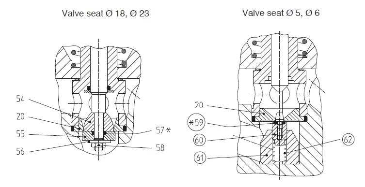
Valve plate (with valve seat Ø 5 and 6 mm)
In the last series of the gas pressure regulator HON 200 with a valve seat with Ø 5 and 6 mm, a connection thread relatively small is used between the valve stem and the valve plate.
To avoid function problems when damages occur on the connection (due to an inadmissible opening moment, inadmissible test pressure, etc.), the valve plate contained an additional spring suspension. We recommend to install this spring suspension (see page 5) also for the previous parts with a valve seat ø 5 and 6 mm. The equipment set (part nr. 19 082 918) can be installed with the gas pressure regulator without any problems.
Torque
| pos. no. | torque in Nm |
| 1 | 80 |
| 45 | 80 |
| 22 | 4 |
| 58 | 9 |
| 60 | 3 |
Lubricants
| part (to be greased slightly) | lubricant | part no. |
| all o-rings, insertion plate of diaphragm (7), all sliding surfaces (23) and closing valve (60) | silicone grease | 00 027 081 |
| all fastening and pipe screws | high duty grease | 00 027 058 |
Spare Parts
Spare Parts Drawing HON 200
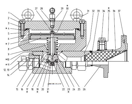
* Parts marked by an asterisk (*) to be kept in stock for maintenance
Spare Parts Drawing HON 200
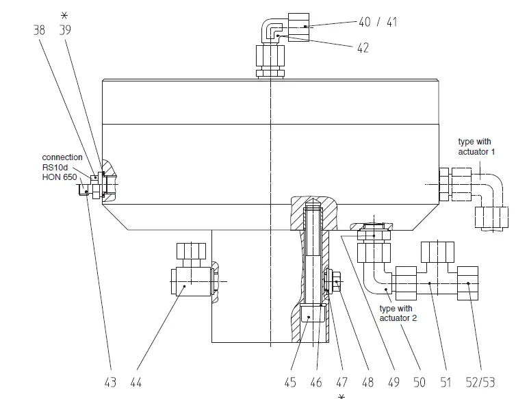
Parts marked by an asterisk (*) to be kept in stock for maintenance
Spare parts list HON 200
| pos. no. | description | material | part no. |
| 1 | cylinder screw disc cap of the actuator body, alternatively: actuator 1actuator 2 o-ring, alternatively: actuator 1 actuator 2 cap of the actuator body, alternatively: actuator 1 actuator 2 fastening plate alternatively: actuator 1 actuator 2 pre-formed diaphragm, alternatively: actuator 1 actuator 2 main diaphragm plate, alternatively: actuator 2 pressure spring, alternatively: for valve seat Ø 5 and 6 mm £ 100 mbar for valve seat Ø 5 and 6 mm >100 mbar for valve seat Ø 8, 12, 18 and 23 mm o-ring o-ring cap nut (Inlet and Outlet), alternatively: for tube: Ø18 mm Ø 22 mm Ø 25 mm Ø 28 mm Ø 38mm Ø 42mm compression joint (Inlet and Outlet), alternatively: for tube: Ø18 mm Ø 22 mm Ø 25 mm Ø 28 mm Ø 38 mm Ø 42 mm | St | 00 010 373 |
| 2 | St | 00 014 136 | |
| 3 | |||
| – | LM | 10 009 465 | |
| – | LM | 10 009 475 | |
| 4* | |||
| – | KG | 00 020 324 | |
| – | KG | 00 020 396 | |
| 5 | |||
| – | LM | 10 009 464 | |
| – | LM | 10 009 474 | |
| 6 | |||
| – | LM | 10 002 290 | |
| – | LM | 10 002 390 | |
| 7* | |||
| – | KG | 10 002 288 | |
| – | KG | 10 002 388 | |
| 8 | |||
| – | LM | 10 009 466 | |
| – | LM | 10 009 476 | |
| 9 | |||
| – | FSt | 10 000 866 | |
| – | FSt | 10 011 024 | |
| – | FSt | 10 009 485 | |
| 10* | KG | 00 020 435 | |
| 11* | KG | 00 020 375 | |
| 12 | |||
| – | St | 00 030 808 | |
| – | St | 00 030 810 | |
| – | St | 00 030 811 | |
| – | St | 00 030 812 | |
| – | St | 00 030 814 | |
| – | St | 00 030 815 | |
| 13 | |||
| – | St | 00 030 097 | |
| – | St | 00 030 909 | |
| – | St | 00 030 910 | |
| – | St | 00 030 911 | |
| – | St | 00 030 913 | |
| – | St | 00 030 914 |
Parts marked by an asterisk * to be kept in stock for maintenance
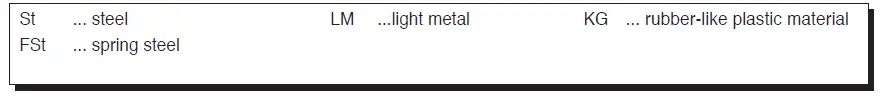
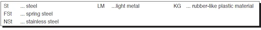
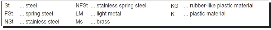
Material – key :
| pos. nn. | description | material | part no. |
| 14 | nozzle (Inlet and Outlet), alternatively: for tube: Ø18 mm Ø 22 mm Ø 25 mm Ø 28 mm Ø 38 mm Ø 42 mm reduction piece (Inlet and Outlet), alternatively: for tube: Ø18 mm Ø 22 mm Ø 25 mm and Ø 28 mm distance ring o-ring closing plate o-ring valve seat, alternatively: for valve: Ø 5 mm Ø 6 mm Ø 8 mm Ø 12 mm Ø 18 mm Ø 23 mm valve plate, alternatively: for valve: Ø 8 mm Ø 12 mm hexagon nut valve stem, alternatively: for valve: Ø 5 mm Ø 6 mm Ø 8 mm Ø 12 mm Ø 18 et 23 mm valve stem conduction body without reducing outlet duct body in aluminium body in steel flange (Inlet and Outlet), alternatively: DN 25, PN 25 and PN 40 DN 25, ANSI 300 RF DN 25, ANSI 300 RJ DN 25, ANSI 600 RF DN 25, ANSI 600 RJ | ||
| – | St | 00 030 157 | |
| – | St | 00 030 158 | |
| – | St | 00 030 159 | |
| – | St | 00 030 160 | |
| – | St | 00 030 161 | |
| – | St | 00 030 162 | |
| 15 | |||
| – | St | 10 005 922 | |
| – | St | 10 005 923 | |
| – | St | 10 005 924 | |
| 16* | LM | 00 018 687 | |
| 17* | KG | 00 020 482 | |
| 18 | Ms | 10 009 483 | |
| 19* | KG | 00 020 434 | |
| 20 | |||
| – | NSt | 10 022 680 | |
| – | NSt | 10 022 681 | |
| – | NSt | 10 009 494 | |
| – | NSt | 10 009 504 | |
| – | NSt | 10 009 514 | |
| – | NSt | 10 009 524 | |
| 21* | |||
| – | K | 10 009 493 | |
| – | K | 10 009 503 | |
| 22 | St | 10 009 526 | |
| 23* | |||
| – | NSt | 10 009 479 | |
| – | NSt | 10 009 497 | |
| – | NSt | 10 009 436 | |
| – | NSt | 10 009 435 | |
| – | NSt | 10 009 511 | |
| 24 | Ms | 10 009 484 | |
| 25 | |||
| – | Al | 10 009 461 | |
| – | St | 10 009 470 | |
| 26 | |||
| – | St | 10 009 536 | |
| – | St | 10 009 445 | |
| – | St | 10 009 442 | |
| – | St | 10 009 537 | |
| – | St | 10 009 538 |
Parts marked by an asterisk * to be kept in stock for maintenance
Material – key:

| pos. no. | description | material | part no. |
| – | DN 40, PN 25 and PN 40 | St | 10 009 538 |
| – | DN 40, ANSI 300 RF | St | 10 009 539 |
| – | DN 40, ANSI 300 RJ | St | 10 009 447 |
| – | DN 40, ANSI 600 RF | St | 10 009 448 |
| – | DN 40, ANSI 600 RJ | St | 10 009 540 |
| – | DN 50, PN 25 and PN 40 | St | 10 009 542 |
| – | DN 50, ANSI 300 RF | St | 10 009 449 |
| – | DN 50, ANSI 300 RJ | St | 10 009 444 |
| – | DN 50, ANSI 600 RF | St | 10 009 543 |
| – | DN 50, ANSI 600 RJ | St | 10 009 544 |
| 27 | hexagonal nut | St | 00 013 005 |
| 28* | sealing ring | LM | 00 018 689 |
| 29 | straight threaded union piece | NSt | 10 009 468 |
| 30* | safety ring | FSt | 00 014 121 |
| 31 | disc screw | St | 00 010 487 |
| 32 | body, noise reducing outlet duct | ||
| – | DN 80, PN 40 | St | 10 010 214 |
| – | DN 80, ANSI 600 RF | St | 10 010 220 |
| – | DN 100, PN 40 | St | 10 010 224 |
| – | DN 100, ANSI 600 RF | St | 10 010 222 |
| 33 | filling body | FSt | 00 026 415 |
| 34 | closing screw | St | 00 025 578 |
| 35* | sealing ring | LM | 00 018 684 |
| 36 | rectifying cone, alternatively: | ||
| – | DN 80 | St | 10 012 085 |
| – | DN 100 | St | 10 012 036 |
| 37 | circlip, alternatively: | ||
| – | DN 80 | FSt | 00 019 128 |
| – | DN 100 | FSt | 00 019 174 |
| 38 | closing screw | St | 00 026 175 |
| 39* | sealing ring | LM | 00 018 689 |
| 40 | cap nut | St | 00 030 803 |
| 41 | compression joint | St | 00 030 903 |
| 42 | nozzle | St | 00 031 207 |
| 43 | nozzle | St | 00 030 111 |
| 44 | union piece | St | 00 031 930 |
| 45 | cylinder screw | St | 00 010 372 |
| 46 | disc | St | 00 014 136 |
| 47* | sealing ring | LM | 00 018 842 |
| 48 | closing screw | St | 00 026 175 |
| 49 | nozzle | St | 00 030 038 |
| 50 | nozzle | St | 00 031 213 |
Parts marked by an asterisk * to be kept in stock for maintenance
Material – key:
| pos. no. | description | material | Part no. |
| 51 | throttling valve | St/KG/Ms | 10 004 060 |
| 52 | cap nut | St | 00 030 804 |
| 53 | compression ring | St | 00 030 904 |
| 54 | valve cone, alternatively: | ||
| – | for valve Ø 18 mm | NSt | 10 009 515 |
| – | for valve Ø 23 mm | NSt | 10 009 525 |
| 55 | valve plate, alternatively: | ||
| – | for valve Ø 18 mm | K | 10 009 513 |
| – | for valve Ø 23 mm | K | 10 009 523 |
| 56 | disc | St | 00 014 137 |
| 57* | o-ring | KG | 00 020 225 |
| 58 | safety nut | St | 00 013 132 |
| 59* | sealing ring | KG | 10 009 481 |
| 60 | closing valve | LM | 10 009 582 |
| 61 | guide piece | K | 10 009 587 |
| 62 | pressure spring | NFSt | 00 027 215 |
| equipment set for supsension with valve spring | 19 082 918 | ||
| valve seat Ø 5 and 6 mm | |||
| (pos. nr. : 59, 60, 61, 62) |
Parts marked by an asterisk * to be kept in stock for maintenance
Material – key:
For More Information
To learn more about Honeywell’s
Advanced Gas Solutions, visit
www.honeywellprocess.com or contact your Honeywell account manager
GERMANY
Honeywell Process Solutions
Honeywell Gas Technologies GmbH
Osterholzstrasse 45
34123 Kassel, Germany
Tel: +49 (0)561 5007-0
Fax: +49 (0)561 5007-107
HON 200.20
2017-01
© 2017 Honeywell International Inc.


