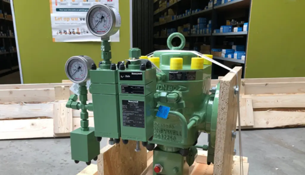
Honeywell HON 380 Gas Medium Pressure Regulators
 The HON 380 features excellent control and lock-up properties which makes it ideal for use in public gas supply grids and in industrial systems. Another plus point is the fact that it delivers outstanding ease of maintenance.
The device with inlet pressure compensation has a spring-loaded measuring unit. The HON 380 is fitted with an integral safety shutoff valve for overpressure and under pressure shut-off.
The HON 380 has a modular design. This means that the entire regulating assembly can be removed and replaced while the housing can remain in the pipeline. This, in turn, means that routine maintenance work can be carried out at the workshop.
The HON 380 is suitable for a wide range of applications such as use in district regulating stations and installations for process gas supply. It can be used for the gases listed in DVGW Code of Practice G 260 and neutral, non-aggressive gases, with other gases on request.
The devices hold an EC-type examination certificate under the Pressure Equipment Directive 2014/68/EU in association with DIN EN 334 and DIN EN 14382. Registration number: CE-0085……
FEATURES


- Max. inlet pressure: 20 bar
- High flow rate
- Easy maintenance as the function units can be exchanged
- Integrated SSV
- SSV optionally available in function class A or B
- Pressure equalization valve (internal bypass) integrated in the SSV control element
- Nominal sizes DN 25, DN 50, DN 80, DN 100
- Flanged connections to EN 1092-2, PN 16 or ANSI 150
- Ambient and operating temperature range: Class 2, -20°C to +60°C
| TECHNICAL DATA | ||||
| Maximum allowable pressure PS Max. inlet pressure pumax | 16 bar/20 bar differential safe (DS) (depending on flange design) | |||
| 16 bar/20 bar | ||||
| Characteristic device size HON 380 Inlet/Outlet | Valve seat diameter [mm] | Valve flow coefficient KG* in (m³/h)/ bar; Without noise reduction | ||
| HON 380 Noise reduction Type of connection Cast steel body | DN 25/DN 25 | 25 | 390 | |
| DN 50/DN 50 | 50 | 1440 | ||
| DN 80/DN 80 | 80 | 3370 | ||
| DN 100/DN 100 | 100 | 4700 | ||
| -10% of specified KG value | ||||
| PN 16 DIN flanges and Class 150 to ANSI 16.5 | ||||
| Accuracy class and Lock-up pd range pressure class [bar] | Accuracy class AC | Lock-up pressure class SG | ||
| Lock-up pressure zone class Ambient and operating temperature range (DIN EN 334) Strength, tightness and function Explosion protection CE mark according to the Pressure Equipment Directive 2014/68/EU (PED) | 0.02 – 0.1 | 10 | 30 | |
| 0.1 – 0.5 | 5 | 10 | ||
| 0.5 – 2 | 2.5 | 5 | ||
| SZ 2.5 | ||||
| Class 2: -20°C to +60°C | ||||
| according to DIN EN 334 and DIN EN 14382 | ||||
| The mechanical components of the device do not have any inherent potential ignition sources among them, nor do they have any hot surfaces and therefore do not fall into the scope of ATEX 2014/34/EU. The electronic accessories used satisfy the ATEX requirements.
| ||||
| Material details Regulator | SSV | |||
| Valve body Diaphragm case Valve seats Valve plate and O-rings Valve stem Diaphragms Plastic parts Adjusting springs | Cast steel | |||
| Sheet steel/Al alloy | Al cast alloy and Al wrought alloy | |||
| Al alloy | Cast steel | |||
| NBR | ||||
| Stainless steel | Stainless steel | |||
| NBR | ||||
| POM | ||||
| Spring steel wire | ||||
OPTIONS
- Noise reduction
- Without SSV
- SSV with manual release
- SSV with electromagnetic remote release
- Electrical SSV “CLOSED” position indicator using inductive proximity initiator and intrinsically safe circuit
- Vent limiter HON 915 (SSV/RA) or On/Off valve HON 919 (SSV)
Valve flow coefficient for natural gas: d = 0,64 (pn = 0,83 kg/m³), tu = 15°C
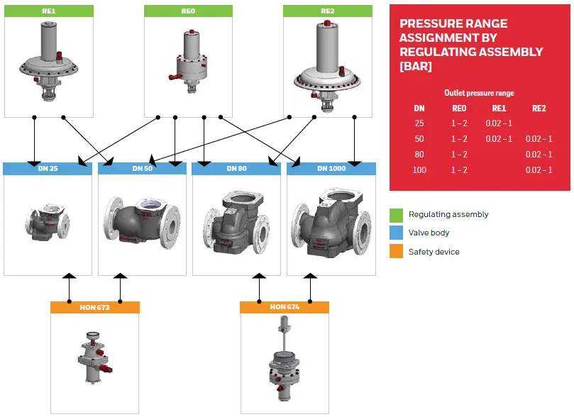
| TABLE OF SPRING RANGES PER REGULATING ASSEMBLY | ||||||||
| Spring | ||||||||
| Part No. | RE0 | Wire Ø [mm] | RE1 Part No. | Wire | RE2 Part No. | Wire | Color | |
| Set range | ||||||||
| Wds [mbar] | ||||||||
| 20 – 30 | 10007241 | 3.6 | 1505607 | 5 | Signal blue | |||
| 25 – 50 | 10003629 | 4 | 10009068 | 6.3 | Gray | |||
| 45 – 75 | 15055022 | 4.5 | 15056072 | 7 | Gentian blue | |||
| 70 – 100 | 10003630 | 4.5 | 10009069 | 7 | Yellow | |||
| 90 – 160 | 15055023 | 5.3 | 15056073 | 8 | Flame red | |||
| 150 – 200 | 10003631 | 5.3 | 10009070 | 8 | Brown | |||
| 190 – 260 | 15055024 | 6.3 | 15056074 | 9 | Nut brown | |||
| 250 – 300 | 10003632 | 6.3 | 15056075 | 9 | Light red | |||
| 290 – 360 | 15055025 | 7 | 15056076 | 10 | Colza yellow | |||
| 350 – 400 | 10003633 | 7 | 10009072 | 10 | Dark red | |||
| 390 – 500 | 15055026 | 7.5 | 10009073 | 11 | Light blue | |||
| 490 – 560 | 15055027 | 8.5 | 15056077 | 11 | Colza yellow | |||
| 550 – 660 | 15055028 | 9 | 15056078 | 12 | Cream | |||
| 650 – 760 | 15055029 | 9.5 | 15056079 | 12 | Gentian blue | |||
| 750 – 800 | 10012564 | 9.5 | 10009164 | 13 | Emerald green | |||
| 790 – 900 | 15055030 | 10 | 15056081 | 13 | Flame red | |||
| 890 – 1000 | 15055031 | 10 | 10009165 | 14 | Black | |||
| 1000 – 2000 | 1000916 | 12 | White | |||||
| 1500 – 2000 | 1000916 | 13 | Green | |||||
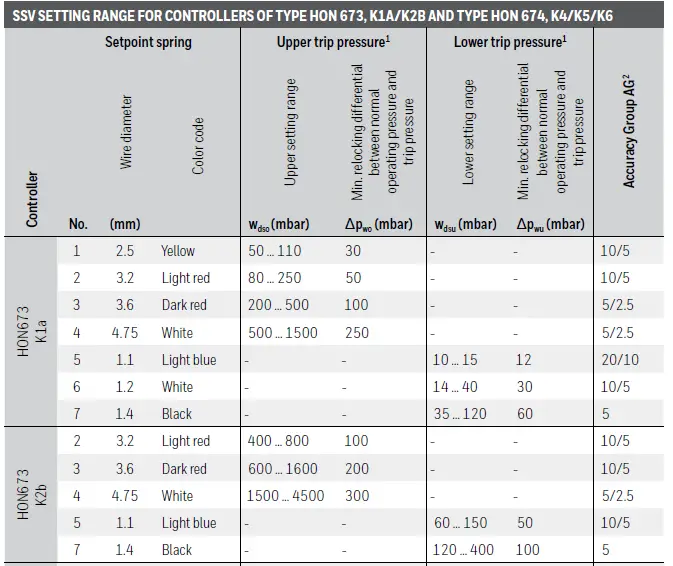
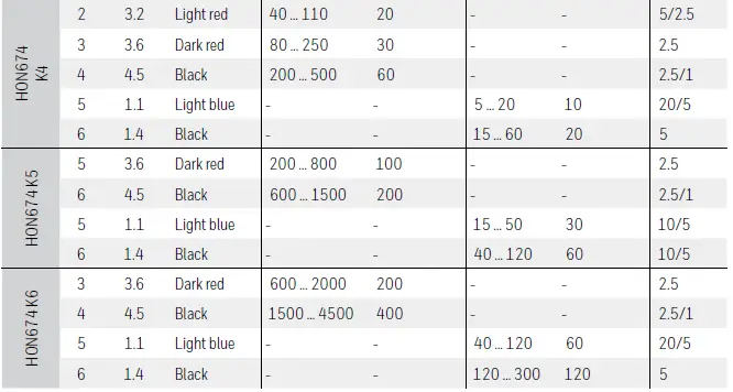
- PLEASE NOTE: If the controller is set for both the upper and lower trip pressure, setpoint values for the upper and lower trip pressure (pdso and pdsu) must be at least 10% greater than the total of the values specified for Δpwo and Δpwu (pdso-pdsu)min = 1.1 * (Δpwo + Δpwu)
- The higher AG group applies to the first half of the setting range, the lower AG to the second half.
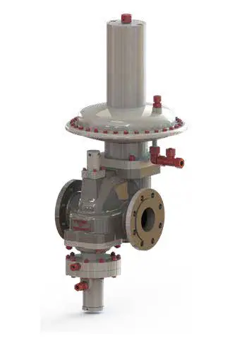
MECHANICAL CONSTRUCTION
The direct acting gas pressure regulator HON 380 is designed to keep
the outlet pressure of a gaseous medium as constant as possible in the connected downstream pipeline (regulating line), regardless of the influence of interfering values such as inlet pressure and/or gas consumption changes. The device consists of the valve body and the function units
“GPR with regulating assembly” and “SSV controller/control unit”.
After undoing the fastening screws, the complete function units can easily be removed from the valve body so that they can be subjected to a visual inspection during scheduled maintenance work. In the event of a defect, it is possible to replace the function units quickly with tested replacement units and relocate the maintenance work from the gas pressure regulating station to the workshop. The outlet pressure for regulating is supplied to the GPR regulating assembly and the SSV controller through measuring lines.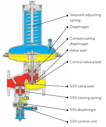
OPERATION
The measuring diaphragm in the regulating assembly records the actual value
of the outlet pressure and compares it to the reference value specified by the setpoint spring. A standard deviation directly influences the control element setting via the valve stem. The change in flow rate brought about by this results in adjusting the outlet pressure actual value to the setpoint value. If the consumption rate is zero, the device closes tight and the lock-up pressure is applied to it.
The control element on the safety shut-off valve on the inlet side shuts down
the gas flow if the outlet pressure in the regulating line is above or below a specific trip pressure. During this process, the SSV measuring diaphragm
moves with the switch sleeve into the appropriate release position while the spherical locking mechanism releases the SSV valve stem and the SSV control element closes. The SSV can only be locked in its open position by hand if
the outlet pressure at the measuring site differs from the set trip pressure setpoint by at least the specified relocking differentials for high or low pressure. The SSV can also be fitted with a manual or remote release as an option. In addition, it can be designed in function class A (with a diaphragm break safety device) and B (without a diaphragm break safety device) as an option.
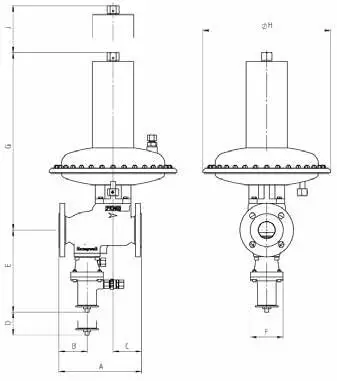
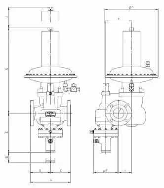
HON 380 in DN 80, DN 100
| DIMENSIONS/WEIGHT | |||||||||||
| Nominal | Valve body | D mm | Safety shut-off valve E* ØF mm mm | ||||||||
| size | A | B | C | X | Y | ||||||
| mm | mm | mm | mm | mm | |||||||
| DN 25 (1’’) | 184 | 64 | 72 | 75 | 255 | 105 | |||||
| DN 50 (2’’) | 254 | 87 | 87 | 80 | 255 | 105 | |||||
| DN 80 (3’’) | 298 | 149 | 149 | 190 | 95 | 250 | 300 | max. 180 | |||
| DN 100 (4’’) | 352 | 185 | 164 | 225 | 110 | 300 | 310 | max. 180 | |||
| GAS PRESSURE REGULATOR WITH REGULATING ASSEMBLY | |||||||||||
| Nominal | RE1 | RE2 | RE0 | ||||||||
| size | G | ØH | J | G | ØH | J* | G | ØH J | |||
| mm | mm | mm | mm | mm | mm | mm | mm mm | ||||
| DN 25 (1’’) DN 50 (2’’) DN 80 (3’’) DN 100 (4’’) | 405 | 297 | 105 | – | 525 |
250 | 105 | ||||
| 410 | 110 | 550 | 395 | 110 | 525 | 110 | |||||
| – | 640 | 200 | 620 | 200 | |||||||
| 630 | 205 | 610 | 205 | ||||||||
| APPROX. WEIGHT [KG] | |||||||||||
| Nominal | RE1 | RE2 | RE0 | ||||||||
| size | With | Without | With | Without | With | Without | |||||
| SSV | SSV | SSV | SSV | SSV | SSV | ||||||
| DN 25 (1’’) | 18 | 16 | – | 34 | 32 | 34 | |||||
| DN 50 (2’’) | 24 | 22 | 35 | 41 | 38 | 41 | |||||
| DN 80 (3’’) | – | – | 73 | 79 | 71 | 79 | |||||
| DN 100 (4’’) | – | – | 89 | 95 | 85 | 95 | |||||
Space for removal
| CONNECTION OF MEASURING AND BREATHER LINES | |||
| RE0 | Actuator SSV controller/control unit Measuring line Breather line Measuring and breather line | ||
| Pipe 16 x 2 (thread G ½) | Pipe 12 x 1.5 (thread G ½) | Pipe 12 x 1.5 (thread G 3/8) | |
| RE1 | Pipe 12 x 1.5 Pipe 12 x 1.5 on the device | Pipe 12 x 1.5 (thread G ½) | |
| RE2 | Pipe 16 x 2 Pipe 12 x 1.5 on the device | Pipe 12 x 1.5 (thread (G ½) | |
Pipe unions to DIN EN ISO 8434-1 (DIN 2353)
For more information
Visit www.process.honeywell.com or contact your Honeywell Account Manager.
Honeywell Process Solutions
2101 City West Blvd, Houston, TX 77042
Honeywell House, Skimped Hill Lane Bracknell, Berkshire, England RG12 1EB UK
Building #1, 555 Huanke Road, Zhangjiang Hi-Tech Industrial Park, Pudong New Area, Shanghai 201203
www.process.honeywell.com
DTS-22-18-EN | 441D | 03/22
© 2022 Honeywell International Inc.


