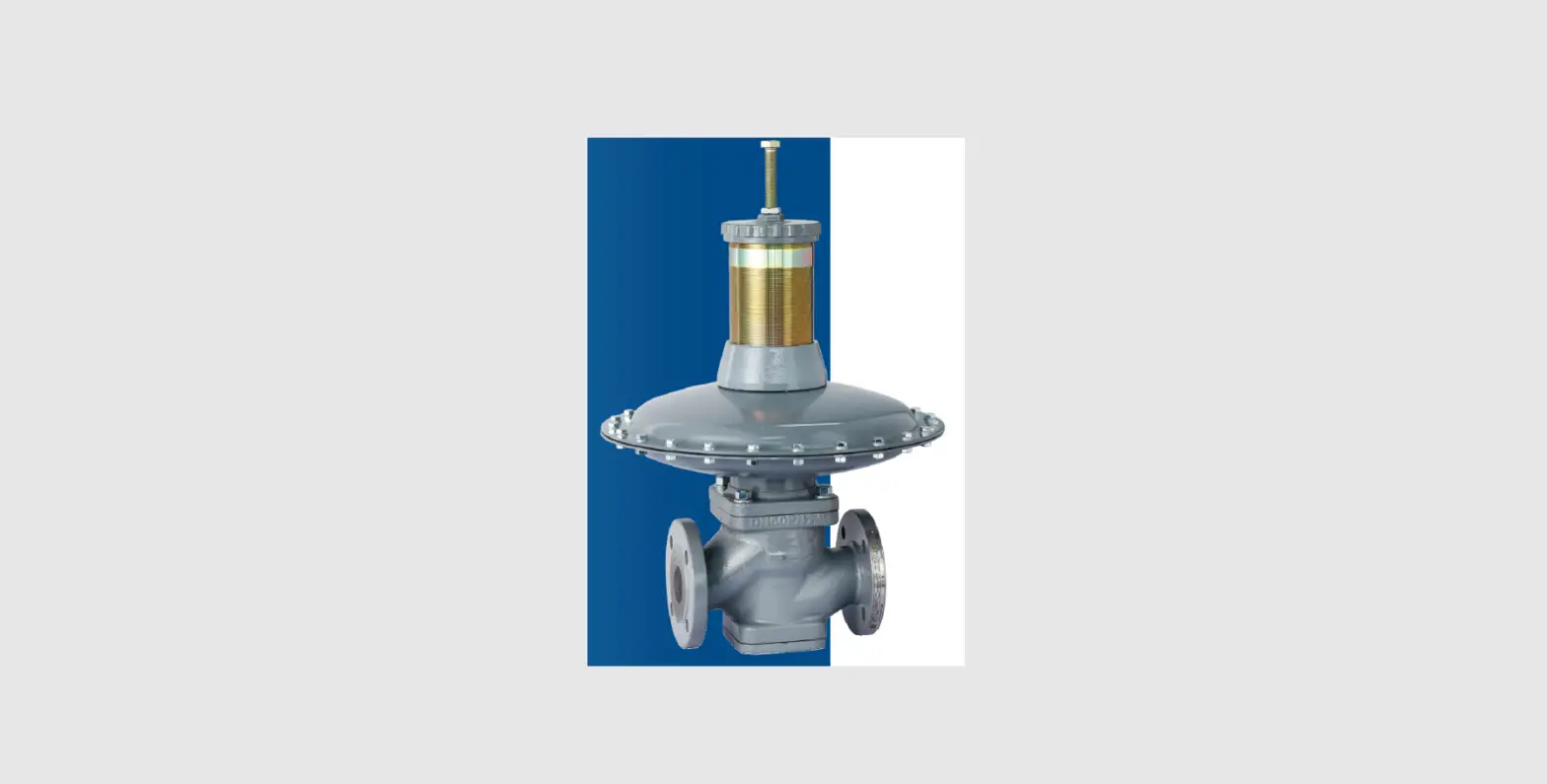
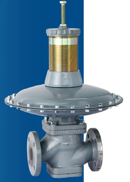
EMERSON S Series Gas Pressure Regulator
WARNING
Failure to follow these instructions or to properly install and maintain this equipment could result in an explosion, fire and/or chemical contamination causing property damage and personal injury or death. Jeon regulators must be installed, operated and maintained in accordance with federal, state and local codes, rules and regulations and Emerson Process Management Regulator Technologies, Inc. instructions. If the regulator vents process fluid or a leak develops in the system, service to the unit may be required. Failure to correct trouble could result in a hazardous condition. Installation, operation and maintenance procedures performed by unqualified personnel may result in improper adjustment and unsafe operation. Either condition may result in equipment damage or personal injury. Call qualified personnel when installing, operating and maintaining the S series pressure regulator.
Introduction
The S Series pressure regulator is a spring-loaded direct-acting gas pressure regulator. Applications: pressure regulation and stabilization of medium and low pressure gas pipeline networks, residential quarters, industrial and commercial users, and direct combustion equipment. Applicable medium: natural gas, artificial gas, liquefied petroleum gas and other non-corrosive gases.
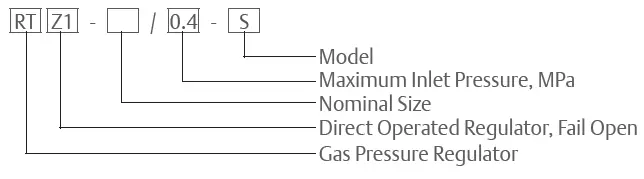
Example: RTZ1-50/0.4-S It means that this is an S Pressure Regulator, Direct Operated, Fail Open, with Body Size DN 50 (Inlet), 0.4 MPa Maximum Inlet Pressure.
Specifications
- Inlet pressure range, P1: 0.02 to 0.4 MPa
- Outlet pressure range, P2: 1.5 to 50 KPa (please refer to “5. Selection of Actuators and Springs” for details)
- Pressure stabilization accuracy level, AC: up to AC5
- Closing pressure level, SG: up to SG10
- Working temperature, t:
- Nitrile (NBR), Standard: -20 to 60°C / -4 to 140°F
- Fluorocarbon (FKM): -10 to 60°C /14 to 140°F
| TYPE | INLET AND OUTLET FLANGE, DN | FLANGE RATING |
| S50 | 50 | PN1.6 MPa In line with the standard HG20592 |
| S65 | 65 | |
| S80 | 80 | |
| S100 | 100 | |
| S150 | 150 |
Features
- Modular structure design;
- Fast response speed and large circulation capacity;
- Fully balanced valve core structure, high pressure regulation accuracy;
- Simple structure, convenient operation and maintenance
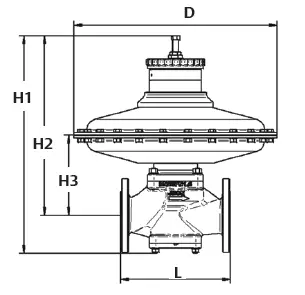
Main Valve Dimensions and Weights
| TYPE | DIMENSION, mm | WEIGHT, kg | ||||
| L | D | H1 | H2 | H3 | ||
| S50 | 254 | 330 / 436 | 675 | 580 | 207 / 213 | 37 |
| S65 | 276 | 436 / 510 | 660 / 695 | 565 / 600 | 190 / 205 | 45 / 55 |
| S80 | 298 | 436 / 510 / 610 | 685 / 720 / 725 | 585 / 620 / 625 | 216 / 223 / 226 | 52 / 62 / 72 |
| S100 | 350 | 436 / 510 / 610 | 735 / 770 / 775 | 615 / 650 /655 | 248 / 255 / 260 | 61 / 71 / 81 |
| S150 | 450 | 436 / 510 / 710 | 835 / 870 / 875 | 630 / 665 / 670 | 278 / 285 / 290 | 118 / 128 / 152 |
| Note: Size D is determined by the actuator specifications selected for the outlet pressure adjustment range of the pressure regulator, see tables in Section 5. | ||||||
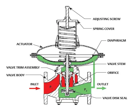
Structure and Principle of Operation
The S Series pressure regulator is composed of the valve body, valve core assembly, actuator and other parts. The principle of operation of the pressure regulator (see Figure 2): The outlet pressure of the regulator is set through the adjusting screw of the main actuator spring. When gas consumption increases at downstream, the outlet pressure, P2 tends to drop. This pressure drop is sensed below the main diaphragm, causing the main diaphragm to move down, as a result of the acting main actuator spring. The main actuator spring overcomes the pressure beneath the diaphragm and pushes the diaphragm downward, causing the valve disk, which is connected through the stem, to move away from the orifice and creates an opening. This will allow the gas to flow downstream keeping the outlet pressure constant. When the amount of gas increases at the downstream of the regulator, the operating process will be in reverse until the regulator is closed.
Selection of Actuators and Springs
| ACTUATOR | PRESSURE REGULATING RANGE, KPa | DIAMETER OF SPRING WIRE, mm | SPRING CODE | COLOR |
|
SNL436 | 1.5 – 2.5 | 4.5 | JJJJ43CXT03 | Black |
| 2.5 – 4 | 5.5 | JJJJ43CXT04 | White | |
| 4 – 8 | 7.0 | JJJJ43CXT05 | Green | |
| 8 – 12 | 7.5 | JJJJ43CXT06 | Blue | |
| 12 – 15 | 9.0 | JJJJ43CXT07 | Red | |
| SNL330 | 25 – 50 | 9.0 | JJJJ43CXT08 | Zinc-coated |
| 6.0 | JJJJ43CXT09 | Zinc-coated |
| ACTUATOR | PRESSURE REGULATING RANGE, KPa | DIAMETER OF SPRING WIRE, mm | SPRING CODE | COLOR |
|
SNL510 | 1.5 – 2.5 | 6.0 | JJJJ44CXT03 | Black |
| 2.5 – 4 | 7.0 | JJJJ44CXT04 | White | |
| 4 – 8 | 8.0 | JJJJ44CXT05 | Green | |
| 8 – 12 | 9.0 | JJJJ44CXT06 | Blue | |
| 12 – 15 | 9.0 | JJJJ43CXT07 | Red | |
| SNL436 | 25 – 50 | 9.0 | JJJJ43CXT08 | Zinc-coated |
| 6.0 | JJJJ43CXT09 | Zinc-coated |
| ACTUATOR | PRESSURE REGULATING RANGE, KPa | DIAMETER OF SPRING WIRE, mm | SPRING CODE | COLOR |
| SNL610 | 1.5 – 2.5 | 6.0 | JJJJ45CXT01 | Purple |
| 2.5 – 4 | 8.0 | JJJJ45CXT02 | Gray | |
| SNL510 | 4 – 8 | 8.0 | JJJJ44CXT05 | Green |
| 8 – 12 | 9.0 | JJJJ44CXT06 | Blue | |
| SNL436 | 12 – 15 | 9.0 | JJJJ43CXT07 | Red |
| 25 – 50 | 9.0 | JJJJ43CXT08 | Zinc-coated | |
| 6.0 | JJJJ43CXT09 | Zinc-coated |
| ACTUATOR | PRESSURE REGULATING RANGE, KPa | DIAMETER OF SPRING WIRE, mm | SPRING CODE | COLOR |
| SNL710 | 1.5 – 2.5 | 7.0 | JJJJ46CXT02 | Red |
| 2.5 – 4 | 8.0 | JJJJ46CXT03 | Zinc-coated | |
| SNL510 | 4 – 8 | 8.0 | JJJJ44CXT05 | Green |
| 8 – 12 | 9.0 | JJJJ44CXT06 | Blue | |
| SNL436 | 12 – 15 | 9.0 | JJJJ43CXT07 | Red |
| 25 – 50 | 9.0 | JJJJ43CXT08 | Zinc-coated | |
| 6.0 | JJJJ43CXT09 | Zinc-coated |
Flow Table
| OUTLET PRESSURE | INLET PRESSURE, MPa | ||||||
| KPa | 0.02 | 0.05 | 0.1 | 0.2 | 0.25 | 0.3 | 0.4 |
| 1.5 | 270 | 500 | 700 | 1000 | 1100 | 1150 | 1250 |
| 2.5 | 270 | 487 | 700 | 1000 | 1100 | 1150 | 1250 |
| 3.0 | 270 | 487 | 700 | 1000 | 1100 | 1150 | 1250 |
| 4.0 | 270 | 487 | 700 | 1000 | 1100 | 1150 | 1250 |
| 6.0 | 270 | 474 | 700 | 1000 | 1100 | 1150 | 1250 |
| 8.0 | 240 | 474 | 700 | 1000 | 1100 | 1150 | 1250 |
| 10 | 230 | 460 | 700 | 1000 | 1100 | 1150 | 1250 |
| 12 | 192 | 460 | 700 | 1000 | 1100 | 1150 | 1250 |
| 15 | 167 | 448 | 700 | 1000 | 1100 | 1150 | 1250 |
| 25 | – – – – | 385 | 700 | 1000 | 1100 | 1150 | 1250 |
| 30 | – – – – | 330 | 700 | 1000 | 1100 | 1150 | 1250 |
| 50 | – – – – | – – – – | 700 | 1000 | 1100 | 1150 | 1250 |
| OUTLET PRESSURE | INLET PRESSURE, MPa | ||||||
| KPa | 0.02 | 0.05 | 0.1 | 0.2 | 0.25 | 0.3 | 0.4 |
| 1.5 | 320 | 570 | 1100 | 1300 | 1500 | 1700 | 2000 |
| 2.5 | 450 | 700 | 1200 | 1600 | 1800 | 2000 | 2400 |
| 3.0 | 400 | 700 | 1200 | 1600 | 1800 | 2000 | 2400 |
| 4.0 | 380 | 700 | 1200 | 1600 | 1800 | 2000 | 2400 |
| 6.0 | 360 | 700 | 1200 | 1600 | 1800 | 2000 | 2400 |
| 8.0 | 330 | 700 | 1200 | 1600 | 1800 | 2000 | 2400 |
| 10 | 300 | 700 | 1200 | 1600 | 1800 | 2000 | 2400 |
| 12 | 240 | 700 | 1200 | 1600 | 1800 | 2000 | 2400 |
| 15 | 200 | 700 | 1192 | 1600 | 1800 | 2000 | 2400 |
| 25 | – – – – | 600 | 1153 | 1600 | 1800 | 2000 | 2400 |
| 30 | – – – – | 450 | 1100 | 1600 | 1800 | 2000 | 2400 |
| 50 | – – – – | – – – – | 1025 | 1600 | 1800 | 2000 | 2400 |
| OUTLET PRESSURE | INLET PRESSURE, MPa | ||||||
| KPa | 0.02 | 0.05 | 0.1 | 0.2 | 0.25 | 0.3 | 0.4 |
| 1.5 | 600 | 1200 | 1500 | 2000 | 2200 | 2500 | 3000 |
| 2.5 | 700 | 1200 | 1800 | 2200 | 2500 | 2800 | 3200 |
| 3.0 | 700 | 1200 | 1800 | 2200 | 2500 | 2800 | 3200 |
| 4.0 | 700 | 1200 | 1800 | 2200 | 2500 | 2800 | 3200 |
| 6.0 | 650 | 1200 | 1800 | 2200 | 2500 | 2800 | 3200 |
| 8.0 | 550 | 1100 | 1800 | 2200 | 2500 | 2800 | 3200 |
| 10 | 550 | 1100 | 1780 | 2200 | 2500 | 2800 | 3200 |
| 12 | 500 | 1000 | 1770 | 2200 | 2500 | 2800 | 3200 |
| 15 | 240 | 1000 | 1780 | 2200 | 2500 | 2800 | 3200 |
| 25 | – – – – | 850 | 1740 | 2200 | 2500 | 2800 | 3200 |
| 30 | – – – – | 850 | 1700 | 2200 | 2500 | 2800 | 3200 |
| 50 | – – – – | – – – – | 1540 | 2200 | 2500 | 2800 | 3200 |
| OUTLET PRESSURE | INLET PRESSURE, MPa | ||||||
| KPa | 0.02 | 0.05 | 0.1 | 0.2 | 0.25 | 0.3 | 0.4 |
| 1.5 | 1500 | 2400 | 3500 | 4000 | 4200 | 4500 | 5500 |
| 2.5 | 1714 | 2798 | 4000 | 4400 | 4800 | 5000 | 6000 |
| 3.0 | 1674 | 2783 | 4000 | 4400 | 4800 | 5000 | 6000 |
| 4.0 | 1587 | 2750 | 4000 | 4400 | 4800 | 5000 | 6000 |
| 6.0 | 1440 | 2694 | 3987 | 4400 | 4800 | 5000 | 6000 |
| 8.0 | 1326 | 2653 | 3980 | 4400 | 4800 | 5000 | 6000 |
| 10 | 959 | 2537 | 3955 | 4400 | 4800 | 5000 | 6000 |
| 12 | 800 | 2500 | 3900 | 4400 | 4800 | 5000 | 6000 |
| 15 | – – – – | 2400 | 3919 | 4400 | 4800 | 5000 | 6000 |
| 25 | – – – – | 2236 | 3873 | 4400 | 4800 | 5000 | 6000 |
| 30 | – – – – | 2040 | 3815 | 4400 | 4800 | 5000 | 6000 |
| 50 | – – – – | – – – – | 3500 | 4400 | 4800 | 5000 | 6000 |
Note:
- The data in the table is the flow rate with relative density of 0.61 for natural gas under standard conditions. For other media, the data in the table should be multiplied by the corresponding factor. Conversion factor: Artificial Gas: 1.17, Butane: 0.55, Propane: 0.63, Air: 0.78, Nitrogen: 0.79
- “- – – -” means unavailable
- In order to make the pressure regulator work normally, the inlet and outlet pressure in a corresponding table should be indicated when ordering if the flow rate used recently is less than 15%.
Installation and Use
WARNING
Installation, operation and maintenance procedures performed by unqualified personnel may result in improper adjustment and unsafe operation. Either condition may result in equipment damage or personal injury. Only a qualified person shall install, operate and maintain the unit. The user must train relevant personnel or contact the after-sales service of the company
- Install the regulator where it is far from fire source, vibration; and the environment temperature meet requirement, heat tracing is necessary if the installation place temperature is lower than requirement.
- Ensure that pressure rate of the pipeline is corresponding with the pressure range indicated on the regulator nameplate.
- Ensure that flow arrow direction on the regulator is corresponding with pipeline flow direction.
- Clean the pipeline before installing the regulator.
- Install the regulator horizontally. The regulator cannot be installed forcefully when it is connected to the front and rear pipelines.
- When there is a fast opening or closing combustion chamber or valve behind the regulator, there should be a certain volume to avoid drastic rise or fall of pressure caused by the rapid changes in flow rate.
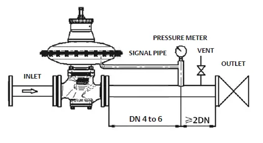
- Filter must be installed on the upstream of the regulator, and there should be an adequate straight pipeline downstream of the regulator. The pressure sensing line measuring point must be located 4 to 6 times the pipe diameter downstream of the regulator. It is recommended that the flow rate in the downstream pipe is ≤30m/s, and the diameter of the straight pipe should be larger than the outlet pipe of the regulator if necessary. (Installation sketch see Figure 3).
WARNING
Forceful installation is strictly prohibited; during pipeline pressure test and purging, please use a blind plate to completely block the pressure regulator or remove the pressure regulator, otherwise the pressure regulator is susceptible to damage
Use
Start-up
- A filter should be installed on the upstream of the regulator;
- Open the shut-off valve;
- Slowly open the inlet valve upstream of the regulator;
- Slightly open the outlet valve downstream of the regulator and observe whether the outlet pressure is the desired set pressure, otherwise set according to Section 2.2;
- Observe for a while until the flow becomes stable;
- Fully open the outlet valves of the regulator.
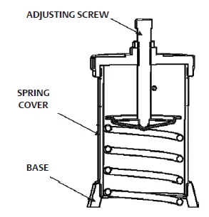
Pressure Regulator Outlet Pressure Setting To change the outlet pressure of the regulator, slowly turn the spring cover to open, then, slowly turn the adjusting screw (clockwise to increase and counter-clockwise to decrease the outlet pressure) to meet the pressure requirement. When adjusting the pressure, make sure that the length of thread engagement between the spring cover and the base cannot be less than 10 mm.
Pressure Regulator Maintenance
General Rules of Maintenance
Close the inlet and outlet valve of the regulator before maintenance, then release all the pressure inside the regulator; avoid damaging orifice, diaphragm etc. parts during assembly or disassembly; check if each moveable parts can be moved freely;Setup the regulator according to Clause 2. The Use of Regulator after maintenance, and check leakage on each sealing part by soap solution. Our company provides training services to maintenance personnel. For other information, please contact our after-sales service department
Routine Maintenance
The management department of the pressure regulator shall determine the daily maintenance cycle according to the gas quality and use situation to ensure the safe use of gas:
- Check the pressure regulator for external leakage using a gas alarm instrument (or soap solution).
- Observe the pressure gauge reading and check the outlet pressure of the pressure regulator.
- Clean the outside of the pressure regulator.
Regular Inspection
It is recommended to carry out regular cleaning and maintenance of the inside of the pressure regulator every 3-6 months on the basis of gas quality and use situation (when the medium is artificial gas, it is recommended to shorten the maintenance cycle to 1-3 months); check or replace the rubber members prone to swelling or aging to ensure safe gas supply and normal use. The management department of the pressure regulator should determine the regular maintenance cycle according to the gas quality and use situation to ensure the normal operation of the pressure regulator
- It is recommended to check the lockup pressure of the pressure regulator at least every three months: connect a pressure gauge to the outlet end of the pressure regulator, turn on the switch, slowly close the ball valve at the outlet end of the pressure regulator, record the lockup pressure three minutes later and check whether it is within the normal range. When the lockup pressure of the pressure regulator is normal, there is no need to disassemble the pressure regulator.
- It is recommended to check the inlet pressure setting of the disconnector at least every three months.
- It is recommended to clean and maintain the internal parts of the pressure regulator and shut-off valve every three to six months, check the vulnerable parts such as the disk seal , the diaphragm and the O-ring, and replace the swollen, aging seals with uneven indentation.
- Check the wear and deformation of key components in the pressure regulator, and replace if necessary.
Troubleshooting
| ISSUE | CAUSE | TROUBLESHOOTING |
|
Reduced outlet pressure | Inlet pressure is too low The actual flow exceeds the design flow of the pressure regulator There are too many foreign materials inside the pressure regulator and jamming occurs | Choose a suitable pressure regulator, and clean the inside of the pressure regulator |
|
Lockup pressure rises | Diaphragm is swollen, aging or damaged | Replace the diaphragm |
| Valve port sealing gasket is swollen and aging | Replace the swollen gasket | |
| The O-ring in the disk assembly is damaged | Replace the O-ring | |
| Foreign materials are adsorbed at the valve port or damage happens | Clean or replace the valve port | |
| The pressure regulator is straight through | Adjusting spring is compressed by outrange | Replace the relatively hard spring |
| Outlet Pressure Unstable | Inlet pressure unstable The actual flow rate is much lower than the rated flow rate | Contact operation management department Change to a suitable regulator |
Spare Parts Package of the S Series Pressure Regulator
| SIZE, DN | ACTUATOR | OUTLET PRESSURE, KPa | DISK MATERIAL | SPARE KIT |
|
50 | SNL436 | 1.5 – 25 | Nitrile (NBR) | JJJJB2BX001 |
| SNL330 | 25 – 50 | Nitrile (NBR) | JJJJB2BX002 | |
| SNL436 | 1.5 – 25 | Fluorocarbon (FKM) | ERAA49669A0 | |
| SNL330 | 25 – 50 | Fluorocarbon (FKM) | ERAA49670A0 | |
|
65 | SNL510 | 1.5 – 12 | Nitrile (NBR) | JJJJB3BX001 |
| SNL436 | 12 – 25 | Nitrile (NBR) | JJJJB3BX002 | |
| SNL436HP | 25 – 50 | Nitrile (NBR) | JJJJB3BX002 | |
| SNL510 | 1.5 – 12 | Fluorocarbon (FKM) | ERAA49673A0 | |
| SNL436 | 12 – 25 | Fluorocarbon (FKM) | ERAA49674A0 | |
| SNL436HP | 25 – 50 | Fluorocarbon (FKM) | ERAA49674A0 | |
|
80 | SNL610 | 1.5 – 4 | Nitrile (NBR) | JJJJB4BX001 |
| SNL510 | 4 – 12 | Nitrile (NBR) | JJJJB4BX002 | |
| SNL436 | 12 – 25 | Nitrile (NBR) | JJJJB4BX004 | |
| SNL436HP | 25 – 50 | Nitrile (NBR) | JJJJB4BX004 | |
| SNL610 | 1.5 – 4 | Fluorocarbon (FKM) | ERAA49678A0 | |
| SNL510 | 4 – 12 | Fluorocarbon (FKM) | ERAA49679A0 | |
| SNL436 | 12 – 25 | Fluorocarbon (FKM) | ERAA49680A0 | |
| SNL436HP | 25 – 50 | Fluorocarbon (FKM) | ERAA49680A0 |
| SIZE, DN | ACTUATOR | OUTLET PRESSURE, KPa | DISK MATERIAL | SPARE KIT |
|
100 | SNL610 | 1.5 – 4 | Nitrile (NBR) | JJJJB5BX001 |
| SNL510 | 4 – 12 | Nitrile (NBR) | JJJJB5BX002 | |
| SNL436 | 12 – 25 | Nitrile (NBR) | JJJJB5BX003 | |
| SNL436HP | 25 – 50 | Nitrile (NBR) | JJJJB5BX003 | |
| SNL610 | 1.5 – 4 | Fluorocarbon (FKM) | ERAA49684A0 | |
| SNL510 | 4 – 12 | Fluorocarbon (FKM) | ERAA49685A0 | |
| SNL436 | 12 – 25 | Fluorocarbon (FKM) | ERAA49686A0 | |
| SNL436HP | 25 – 50 | Fluorocarbon (FKM) | ERAA49686A0 | |
|
150 | SNL710 | 1.5 – 4 | Nitrile (NBR) | JJJJB6BX001 |
| SNL510 | 4 – 12 | Nitrile (NBR) | JJJJB6BX002 | |
| SNL436 | 12 – 25 | Nitrile (NBR) | JJJJB6BX003 | |
| SNL436HP | 25 – 50 | Nitrile (NBR) | JJJJB6BX003 | |
| SNL710 | 1.5 – 4 | Fluorocarbon (FKM) | ERAA49690A0 | |
| SNL510 | 4 – 12 | Fluorocarbon (FKM) | ERAA49691A0 | |
| SNL436 | 12 – 25 | Fluorocarbon (FKM) | ERAA49692A0 | |
| SNL436HP | 25 – 50 | Fluorocarbon (FKM) | ERAA49692A0 |
Emerson Asia Pacific Private Limited
- 1 Pandan Crescent
- Singapore 128461
- T: +65 6777 8211
- F: +65 6770 8028
FISHER JEON Gas Equipment (Chengdu) Co., Ltd No. 9, Wukedong 2nd Road, Wuhou Science Technic Park, Chengdu, 610045, P.R. China T: (028) 85360000 F: (028) 85371201 Service T: (028) 85366930 or (028) 85360000 Ext. 1613


