
BAPI 49583 EZ Pressure Sensor
Identification and Overview
BAPI’s EZ Low Pressure Sensor is a true differential pressure transmitter that provides ±1 inches WC (±250 Pacals) in
10 field selectable ranges (see specifications). BAPI’s EZ enclosure is designed for DIN rail, Snaptrack or surface mounting. Five output ranges of 0 to 5, 1 to 5, 0 to 10 and 2 to 10 VDC and 4 to 20 mA are also field selectable for all pressure ranges. The wiring terminal block is pluggable. Pressure units of inches of Water Column or Pascals are field selectable.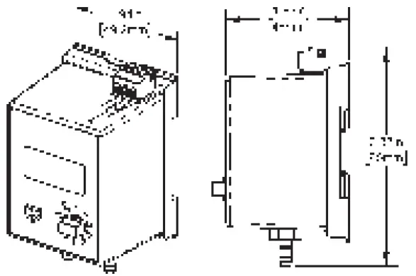
Mounting
The EZ Mount Base has mounting tabs that can be extended or pushed in for the three mounting methods.
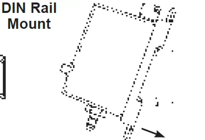
DIN Rail Mounting:
- Pull out the blue mounting tabs.

- Catch the EZ mount hook on DIN rail.

- Rotate the EZ pressure module down until the bottom mounting tab snaps into place on the DIN rail.
- Connect wires and pressure lines as needed.
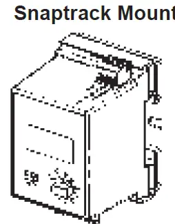
Snap track Mounting:
- Push in the blue mounting tabs.
- Snap the EZ Mount base into the board slots in the 2.75 inch snap track.
- Connect wires and pressure lines as needed.

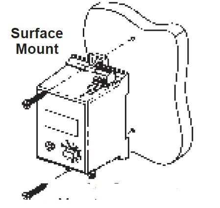
Surface Mounting:
- Pull out the blue mounting tabs.
- Place the EZ Pressure unit against the surface and mark the screw holes.
- Drill 1/8” pilot holes for #8 flathead screws.
- Screw unit to the surface. The holes in the blue mounting tabs are elongated to allow for alignment.
- Connect wires and pressure lines as needed.

Pressure Connections
The Pressure ports are 1/4” barbed fittings.
- Connect the high pressure to the port labeled High
- Connect the low pressure to the port labeled Low.
The output will be the pressure difference between the high and low port.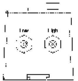
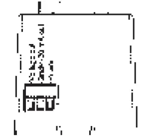
Wiring Termination
BAPI recommends wiring the product with power disconnected. Proper supply voltage, polarity and wiring connections are important to a successful installation. Not observing these recommendations may damage the product and void the warranty.
| Table 1: EZ Pressure Sensor Termination | |||
| Output Signal | Power Terminal | Gnd/4-20mA Terminal | Voltage Output Terminal |
| 4 to 20 mA | 7 to 40 VDC | 4 to 20 mA Signal To Controller Analog Input | Not Used |
| 0 to 5 VDC | 7 to 40 VDC or 6 to 28 VAC | To Controller Ground | 0 to 5 VDC Signal To Controller Analog Input |
| 1 to 5 VDC | 7 to 40 VDC or 6 to 28 VAC | To Controller Ground | 1 to 5 VDC Signal To Controller Analog Input |
| 0 to 10 VDC | 12 to 40 VDC or 9 to 28 VAC | To Controller Ground | 0 to 10 VDC Signal To Controller Analog Input |
| 2 to 10 VDC | 12 to 40 VDC or 9 to 28 VAC | To Controller Ground | 2 to 10 VDC Signal To Controller Analog Input |
4 to 20 mA, “Two Wire” Operation
- Connect the EZ Pressure’s [Power] terminal to a DC voltage of 7 to 40 VDC.
- Connect the [Gnd/4-20 mA Out] terminal to a 4 to 20mA input on your controller.
- The [Voltage Out] terminal is not used for 4 to 20 mA signaling.
0 to 5, 1 to 5, 0 to 10 or 2 to 10 V, “Three Wire” Operation
- Connect the EZ Pressure’s [Power] terminal to:
- 7 to 40 VDC or 6 to 28 VAC (for 0 to 5 or 1 to 5 VDC output units)
- 12 to 40 VDC or 9 to 28 VAC (for 0 to 10 or 2 to 10 VDC output units).
- Connect the terminal labeled [Gnd/4-20 mA Out] to the controller’s ground.
- Connect the [Voltage Out] terminal to an analog input configured for voltage input.

Note: The terminals use a rising block screw terminal to hold the wires. It is possible for the block to be in a partially up position allowing the wire to be inserted under the block. Be sure that the connector screws are turned fully counterclockwise before inserting the wire. Lightly tug on each wire after tightening to verify proper termination.
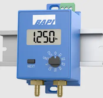
Front Panel Operation
The rotary switch is used to select the pressure range, bi-directional or uni-directional pressure range, output range or to auto zero the unit. The notch in the knob indicates the switch position. The rotary switch is indicating 0 (zero), showing that the switch is in the Auto Zero positions Pressing the NEXT button toggles between values when the rotary switch is in the [+/-] bi-directional or uni-directional pressure or [OUT] output range position. The NEXT button is also used to initiate [0] Auto Zero or change the display mode.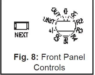
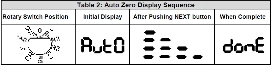
AUTO ZERO SELECT
- Connect the high and low ports together with a short length of tubing without kinks.
- Place the rotary switch into the [0] position. The display will show Aut0.
- Press the NEXT button. The display will show a series of progress bars starting with one bar and ending with four.
- When the Auto Zero is complete, the display will show “done” for about 4 seconds, then Aut0.
- Return the rotary switch to the desired pressure range (see Pressure Range Select).

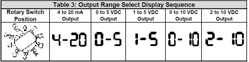
OUTPUT RANGE SELECT
- Place the rotary switch into the [OUT] position.
- Press the NEXT button until the desired output range is showing on the display.
- Return the rotary switch to the desired pressure range (see Pressure Range Select).

PRESSURE RANGE SELECT
Rotate the rotary switch to any of the positions labeled [R1] through [R5] or [CR] for a Custom Range. (Note: Custom Range units will have the pressure range printed on the label.) The display will show the pressure range for 2 to 4 seconds, and then the display shows the differential pressure across the ports.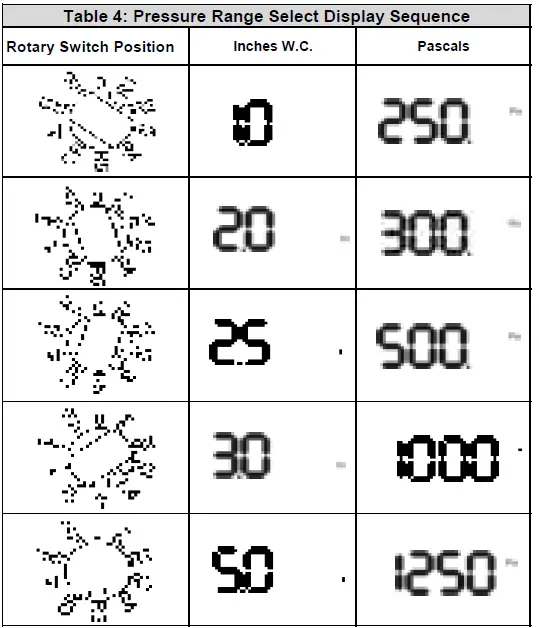
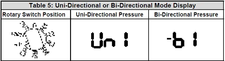
UNI-DIRECTIONAL OR BI-DIRECTIONAL RANGE SELECT
All pressure ranges can be made uni-directional or bi-directional.
- Place the rotary switch into the [+/-] position. The directional mode will show on the display.
- Press the NEXT button until the desired mode is showing on the display.
- Return the rotary switch to the desired pressure range.

UNIT MODE SELECT
You have the ability to toggle between Inches W.C. and Pascals by pressing the next button when the rotary switch is in the UNIT position. When the unit is measuring in Inches W.C. the unit will display In. When the unit is measuring in Pascals the unit will display PA.
Typical Applications
- Duct static pressure monitoring with the BAPI EZ Low Pressure Sensor mounted in a panel with a static probe (ZPS-ACC07) in the duct.

- Air filter pressure drop monitoring with the EZ Low Pressure Sensor mounted in a panel with two static pressure probes (ZPS-ACC07) in the duct.

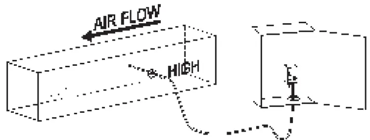
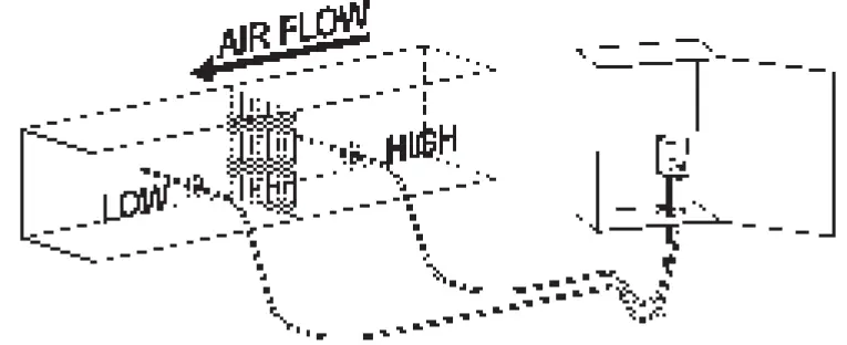
NOTE: Best practice is to form a drip loop in the tubing to prevent condensation from reaching the sensor.
Troubleshooting
POSSIBLE PROBLEMS: POSSIBLE SOLUTIONS:
Display does not light Check power connections for proper power (see specifications below).
Output stuck either high or low or not tracking pressure properly. Remove pressure from ports and perform Auto Zero procedure .
Specifications
- Power:
7 to 40 VDC (4 to 20 mA Output)
7 to 40 VDC or 6 to 28 VAC (0 to 5 or 1 to 5 VDC Output) 12 to 40 VDC or 9 to 28 VAC (0 to 10 or 2 to 10 VDC Output) - Power Consumption:
20 mA max, DC only at 4 to 20 mA Output
4.9 mA max DC at 0 to 5 or 0 to 10 VDC Output 0.12 VA max AC at 0 to 5 or 0 to 10 VDC Output - Load Resistance:
4 to 20 mA Output 850 Ω Maximum @ 24 VDC
0 to 5, 1 to 5, 0 to 10, 2 to 10 VDC Output 6Ω min. - Accuracy:
±0.25% FS at 72°F (22°C)
±0.005” WC (±1.24 Pa) - Stability: ±0.25% F.S. per year
- Overpressure:
Proof: 100” WC (3.6 PSI)
Burst: 300” WC (10.82 PSI) - Media: Clean, dry, non-corrosive gases
- Compensated Temperature Range:
32 to 122°F (0 to 50°C) - Environmental Operating Range:
14°F to 140°F (-10°C to 60°C) - Storage Temp.: -40 to 203°F (-40 to 95°C)
- Humidity: 0 to 95% RH, non-condensing
- Wiring:
Removable terminal block (14 to 24 AWG)*
2 wires (4 to 20mA Current loop)*
3 wires (AC or DC powered, Voltage out)* - Port Size: 1/4” barb (1/8” to 3/16” I.D.)
- Enclosure Material: ABS Plastic, UL94 V-0
- Mounting: DIN Rail, Snap track or Surface
- Agency: RoHS, UL
*BAPI recommends that you do not run wiring for the pressure transmitter in the same conduit as line voltage wiring or with wiring used to supply highly inductive loads such as motors, generators and coils.
Low Pressure Ranges
| Inches of Water Column (WC) Ranges | ||||
| Range | Pressure | Range | Pressure | |
| 71 | 0 to 1.00″ | 76 | ± 1.00″ | |
| 72 | 0 to 2.00″ | 77 | ± 2.00″ | |
| 73 | 0 to 2.50″ | 78 | ± 2.50″ | |
| 74 | 0 to 3.00″ | 79 | ± 3.00″ | |
| 75 | 0 to 5.00″ | 80 | ± 5.00″ | |
| Pascal Ranges | ||||
| Range | Pressure | Range | Pressure | |
| 81 | 0 to 250 Pa | 86 | ± 250 Pa | |
| 82 | 0 to 300 Pa | 87 | ± 300 Pa | |
| 83 | 0 to 500 Pa | 88 | ± 500 Pa | |
| 84 | 0 to 1,000 Pa | 87 | ± 1,000 Pa | |
| 85 | 0 to 1,250 Pa | 90 | ± 1,250 Pa | |
Building Automation Products, Inc., 750 North Royal Avenue, Gays Mills, WI 54631 USA
Tel:+1-608-735-4800
Fax+1-608-735-4804
E-mail:s[email protected]
Web: www.bapihvac.com


