![]()
Robustel R1510 Hardware Manual
R1510
Hardware Manual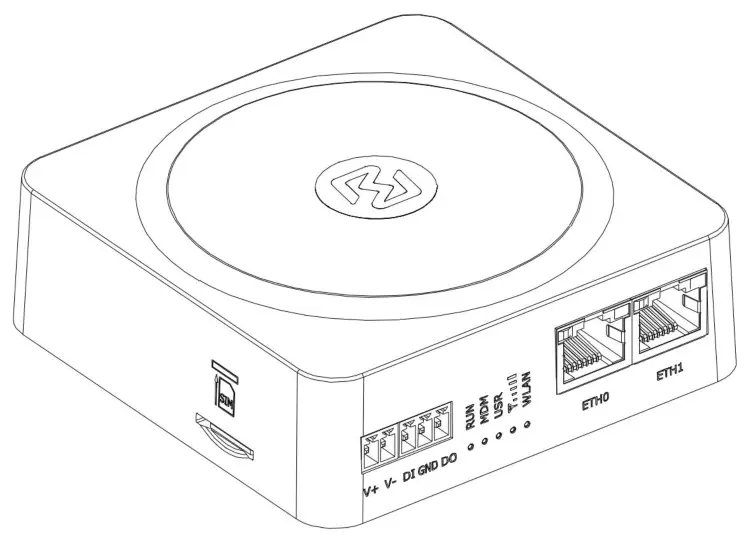
Version: 1.0.0
Date: July 6, 2022
RT048_HM_R1510
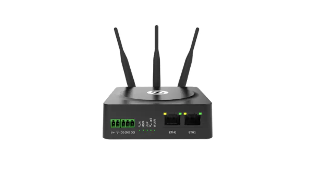
R1510 Industrial Cellular 4G VPN Router
Robustel R1510 Hardware Manual
Regulatory and Type Approval Information
Table 1: Toxic or Hazardous Substances or Elements with Defined Concentration Limits
| Name of the Part | Hazardous Substances | |||||||||
| (Pb) | (Hg) | (Cd) | (Cr(VI)) | (PBB) | (PBDE) | (DEHP) | (BBP) | (DBP) | (DIBP) | |
| Metal parts | 0 | 0 | 0 | 0 | – | – | – | – | – | – |
| Circuit modules | 0 | 0 | 0 | 0 | 0 | 0 | 0 | 0 | 0 | 0 |
| Cables and cable assemblie s | 0 | 0 | 0 | 0 | 0 | 0 | 0 | 0 | 0 | 0 |
| Plastic and polymeric parts | 0 | 0 | 0 | 0 | 0 | 0 | 0 | 0 | 0 | 0 |
| o: Indicates that this toxic or hazardous substance contained in all of the homogeneous materials for this part is below the limit requirement in RoHS2.0. X: Indicates that this toxic or hazardous substance contained in at least one of the homogeneous materials for this part might exceed the limit requirement in RoHS2.0. Indicates that it does not contain the toxic or hazardous substance. | ||||||||||
Radio Specifications
| RF technologies | 2G, 3G, 4G, Wi-Fi |
| Cellular Frequency* | 2G: GSM: B3/B8 |
| 3G: WCDMA: B1/B8 | |
| 4G: LTE FDD: B1/B3/B7/B8/B20/B28A | |
| Max RF power | 33 dBm±2dB@2G, 24 dBm+1/-3dB@WCDMA, 23 dBm±2 dBm@LTE, |
* May vary on difference models.
Document History
Updates between document versions are cumulative. Therefore, the latest document version contains all updates made to previous versions.
| Date | Firmware Version | Document Version | Change Description |
| July 6, 2022 | 5.0.0 | 1.0.0 | Initial release. |
Overview
Robustel R1510 router is a Dual Ethernet port (LAN + WAN) 3G/4G router with advanced software functions at a very competitive price point.
Package Checklist
Before commencing installation ensure your package has the following components: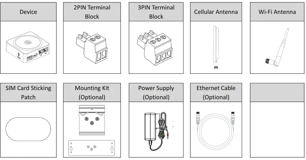
Note: The accessories could be different on specific order.
Panel Layout(May vary on difference models)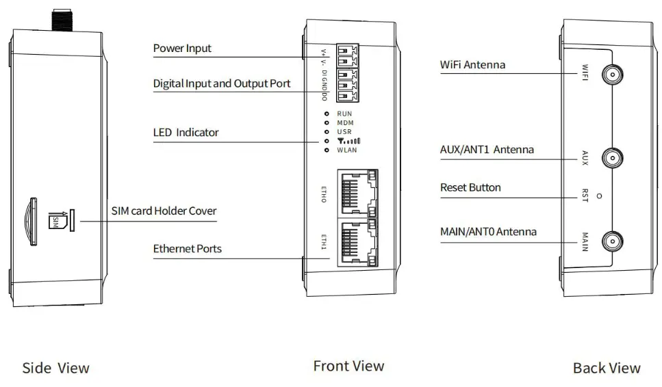
Interface Descriptions
- Power Supply. 2PIN 3.5mm pitch terminal block.
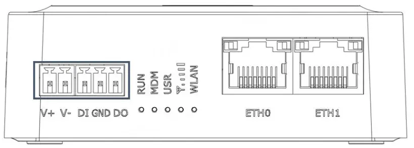
| PIN | Power | DI/DO | Description |
| 1 | V+ | — | Power input Positive, 9-36VDC |
| 2 | V- | — | Power input Negative |
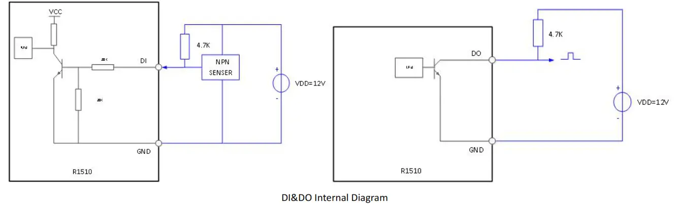
| 3 | — | DI | Digital input (Maximum absolute voltage: 30V. Maximum absolute current: 20mA) |
| 4 | — | GND | Ground |
| 5 | — | DO | Digital output (Maximum absolute voltage: 30V. Maximum absolute current: 20mA) |
|
| |||
2. LED Indicator.
| Name | Color | Status | Description | |
| RUN | Green | On, solid | Router is powered on (System is initializing) | |
| On, blinking | Router starts operating | |||
| Off | Router is powered off | |||
| MDM | Green | On, solid | Link connection is working | |
| On, blinking | Data is sent and received. | |||
| Off | Link connection is not working | |||
| USR | USR-OpenVPN | Green | On, solid | OpenVPN connection is established |
| Off | OpenVPN connection is not established | |||
| USR-IPsec | Green | On, solid | IPsec connection is established | |
| Off | IPsec connection is not established | |||
| RSSI | Green | On, solid | Signal Level: Best Signal Level Wireless module: 21-31dB (signal strength) |
| On, slow blinking (1s) | Signal Level: Average Signal Level Wireless module: 11-20dB (signal moderate) | ||
| On, fast blinking | Signal Level: Abnormal Signal Level Wireless module: 21-31dB (signal weak) | ||
| Off | No signal | ||
| WLAN | Green | On, solid | WLAN is enabled and working properly |
| Green | Off | WLAN is disabled or not working properly |
Note: You can choose the display type of USR LED. For more details, please refer to
RT123_SM_RobustOS Software Manual, Services > Advanced > System >System Settings > User LED Type.
3. Reset Button.
| Function | Operation |
| Reboot | Press and hold the RST button for 2~ 5 seconds under the operating status. |
| Restore to default configuration | Press and hold the RST button for 5~10 seconds, the RUN LED starts blinking quickly, the router will restore to default configuration. |
| Restore to factory default settings | Once the operation of restoring default configuration is performed twice within one minute, the router will restore to factory default settings. |
| Note: The more details please refer to RT123_SM_RobustOS Software Manual, 2.3 Factory Reset. | |
4. Ethernet Ports. There are two Ethernet ports on R1510, including ETH0 (WAN/LAN), and ETH1. Each has two LED indicators. The green one is a link indicator but the yellow one doesn’t mean anything. For details about status, see the table below.
| Ethernet LED Indicator | Status | Description |
| Link indicator (Green) | On, solid | Connection is established |
| On, blinking | Data is being transferred | |
| Off | Connection is not established |
Hardware Installation
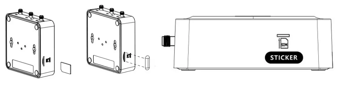
- SIM Card Installation. Insert the SIM cards into the device, then stick the sticker.

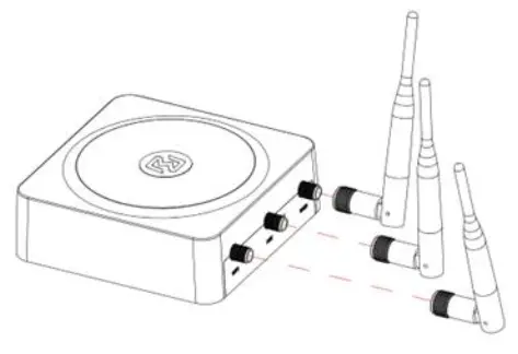
- Antenna Installation. Rotate the antenna into the antenna connector accordingly.

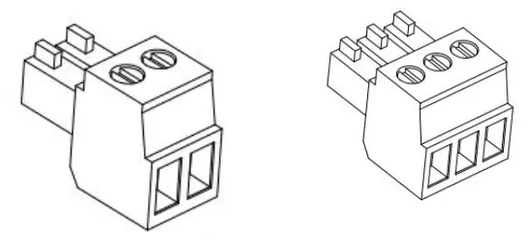
- Terminal Block Installation. Insert the 2PIN、3PIN terminal blocks into the interfaces connector.

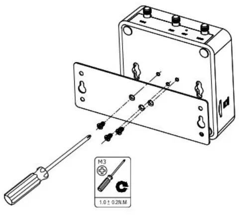
- Mounting Kit installation.
1 Wall mounting 2 DIN rail mounting
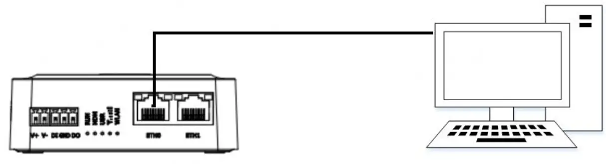
- Connect the Router to a Computer

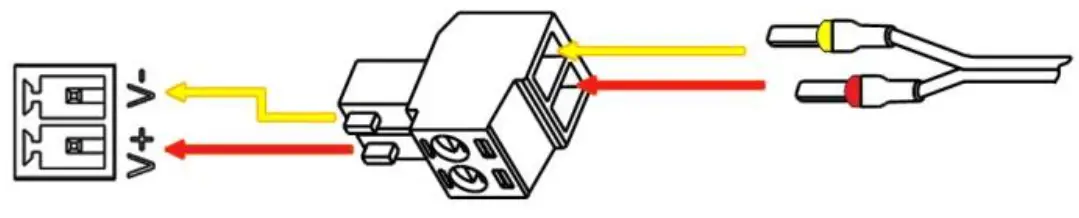
- Power Supply installation. There are two cables associated with the power adapter. Following to the color of the head, connect the cable marked red to the positive pole through a terminal block, and connect the yellow one to the negative in the same way.
Note: The range of power voltage is 9 to 36V DC.
 2 DIN rail mounting
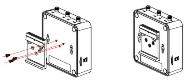
CONNECTING THE POWER CABLE
| COLOR | POLARITY |
| RED | + |
| YELLOW | – |
Login to the Device
- Connect the router’s Ethernet port to a PC with a standard Ethernet cable.
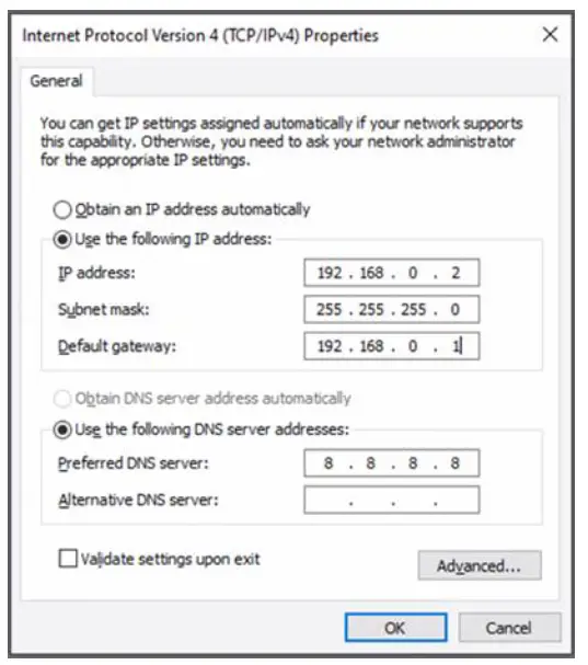
- Before logging in, manually configure the PC with a static IP address on the same subnet as the gateway address, click and configure “Use the following IP address”.

- To enter the gateway’s web interface, type http://192.168.0.1 into the URL field of your Internet browser.
- Use login information shown in the product label when prompted for authentication.

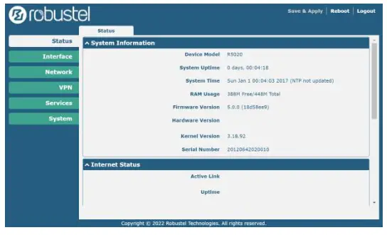
- After logging in, the home page of the web interface is displayed, then you can view system information and perform configuration on the device.

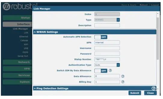
- The automatic APN selection is ON by default, if need to specify your own APN, please go to the menu Interface->Link Manager->Link Setting->WWAN Settings to finish the specific setting.

- The more configuration details please refer to RT123_SM_RobustOS Software Manual. (END)

Simplified EU Declaration of Conformity
We, Guangzhou Robustel Co., Ltd. are located at 501, Building #2, 63 Yongan Road, Huangpu District, Guangzhou, China, declare that this radio equipment complies with all applicable EU directives. The full text of the EU DoC is available at the following internet address: www.robustel.com/certifications/
FCC Declaration of Conformity
This device complies with Part 15 of the FCC Rules. Operation is subject to the following two conditions:
(1) This device may not cause harmful interference.
(2) This device must accept any interference received, including interference that may cause undesired operation.
IC Declaration of Conformity
This device contains licence-exempt transmitter(s)/receiver(s) that comply with Innovation, Science and Economic Development Canada’s licence-exempt RSS(s). Operation is subject to the following two conditions:
(1)This device may not cause interference.
(2)This device must accept any interference, including interference that may cause undesired operation of the device.
Radio Frequency Exposure Statement for IC
This device complies with IC exposure limits set forth for an uncontrolled environment. This device shall be installed
and operated with minimum distance 20cm between the radiator & body.
Related download link![]() Find more product documents or tools at: www.robustel.com/en/documentations/
Find more product documents or tools at: www.robustel.com/en/documentations/
Technical Support
Tel: +86-20-82321505
Email: [email protected]
Web: www.robustel.com
Support: [email protected]
Website: www.robustel.com
©2022 Guangzhou Robustel Co., Ltd.
All rights reserved. Subject to change without notice.


 Router User Guide")


